
I. Equipment Overview and Industry Application Background
The RFID label high-speed composite die-cutting machine, core model RFID-LC100-250 (commonly referred to as the HDS-250 series in the industry), is an automated high-speed processing equipment designed specifically for multi-layer materials such as RFID electronic labels, apparel hang tags, medical tickets, and logistics labels.
Core Specifications
- Specifications: Max material width 250mm (supports 350mm custom extension), max operating speed up to 100m/min
- Material Handling: Max roll diameter 600mm, weight 30kg, max gluing width 230mm
- Precision: Dry INLAY cutting accuracy ≤±0.3mm, transfer accuracy ≤±0.5mm, double-layer printing composite accuracy ≤±0.4mm, contour die-cutting accuracy ≤±0.2mm
- Physical Characteristics: Equipment dimensions approx. 5600mm×1500mm×2300mm, weight approx. 4 tons
- Power: Rated power 40kW, voltage AC380–400V
Core Functions
- Multi-Mode Processing: Supports single-blade, double-blade, and four-blade die-cutting modes; integrates flipping and folding processes; suitable for paper and fabric materials
- High-Speed Stability: Maintains stable 100m/min high speed even with four-row INLAY transfer + three-blade die-cutting combination
- Intelligent Detection: Built-in mark detection, reader TID chip reading, and automatic defective product rejection functions
- Unwinding System: Two types—automatic boxing for sheet materials and multi-row slitting for roll materials—both using independent servo constant tension control to avoid chip damage
- Innovative Design: The innovative INLAY liner collection method eliminates frequent roll changes, significantly reducing noise, space occupation, and costs
- Professional Mechanism: Standard servo floating bar mechanism specifically addresses stretching issues in stretchable materials like self-adhesive labels and aviation baggage tags, reducing downtime and defect rates
Industry Position and Pain Points
In the RFID label production chain, this machine undertakes the integrated tasks of “composite + die-cutting + detection + collection,” directly affecting downstream labeling and packaging efficiency. Current industry pain points include color mark registration accuracy at high speeds, stability of communication remote monitoring, and long-term maintenance costs. While the HDS-250 effectively addresses these with high-precision photoelectric sensors and Omron HMI systems, practical operation still frequently encounters color mark detection alarms and communication configuration issues. This article takes these as entry points to systematically analyze the die-cutting machine’s principles, failure mechanisms, troubleshooting procedures, communication optimization, and full lifecycle maintenance.
II. Core Working Principles of the Die-Cutting Machine
A die-cutting machine is essentially a precision pressure processing equipment, with its working principle based on the mechanical mechanism of “impression + die-cutting shear.” Traditional classifications include flat-bed flat, flat-bed cylinder, and cylinder-cylinder structures. The HDS-250 adopts a cylinder-cylinder (drum-type) structure, offering advantages of continuous high-speed operation without intermittent pauses, suitable for roll-to-roll production.
2.1 Composite Process Flow
Materials from the unwinding shaft (including face material, INLAY chip layer, adhesive liner) pass through servo floating bar deviation correction and tension control before entering the composite station. The composite roller bonds multiple layers at constant pressure (adjustable 0.1–5MPa). Dry INLAY pitch jump is synchronized through precise servo pulse calculation by the PLC. After composite, the material enters the die-cutting station: the rotary die (magnetic or mechanical fixed) presses against the bottom roller, with the blade cutting the contour at micron-level clearance while retaining the liner. Waste is separated by the stripping roller, and the finished product is either slit and collected in rolls or collected as sheets.
Key Parameter Control:
- Tension: Servo closed-loop for unwinding/rewinding, range 0.5–50N (depending on material thickness)
- Speed Synchronization: Spindle motor and all axes locked via electronic gear ratio (electronic cam), error <0.1%
- Pitch Compensation: Real-time feedback from color mark sensors dynamically adjusts servo displacement for dry INLAY position deviations
2.2 Color Mark Detection (Registration Mark) Principle
Color mark detection is the core of die-cutting precision. Materials are pre-printed with black/colored registration marks (eye marks, typically 2–5mm wide, 1–3mm high). The sensor (photoelectric eye) emits LED red/green/blue light and receives reflected/transmitted signals. When a mark passes, the signal intensity changes abruptly (threshold adjustable), triggering the PLC count pulse to align the die-cutting blade with the material.
Sensor Types:
- Reflective Type (Mainstream): Detects surface reflectivity difference, response time <35μs, detection distance 5–50mm
- Contrast Mode: Highest sensitivity to black/white marks
- Working Principle Formula (Simplified):
Detection Signal = K × (Reflectivity Material - Reflectivity Mark)where K is the gain coefficient.Registration Error = (Pulse Count Deviation × Material Speed) / Encoder Resolution
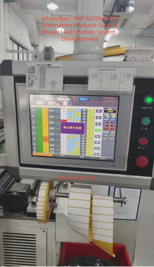
When the HDS-250 screen displays a purple “Confirm Color Detection” box, it is a safety shutdown protection triggered by the sensor missing detection or abnormal signals for N consecutive times (default 3–5 times), preventing off-cut waste.
2.3 Communication and Monitoring System
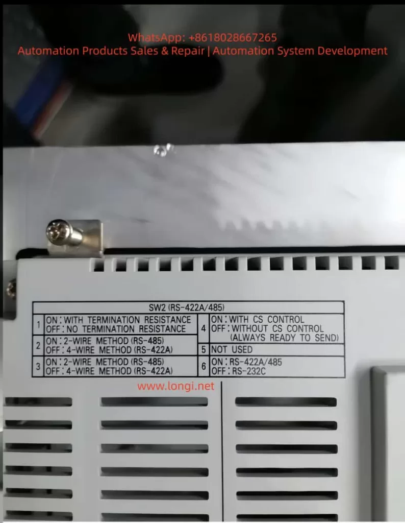
The equipment PLC (typically Omron CP/NX series) and HMI (Omron VO400 series touch screen) exchange data via RS-422A/485 bus. Production tables, parameter settings, and alarm logs are displayed in real-time. The HMI backplane SW2 DIP switch directly determines the physical layer configuration of the communication.
III. Actual Case Failure Analysis: Color Mark Detection Alarms and DIP Switch Communication Issues
The two on-site photos provided by the user clearly present typical scenarios:
- First Photo: HDS-250 operation interface, top-left production table shows real-time output/speed, center large purple box “Confirm Color Detection,” top-right time 17:22:56, green power light on, start/stop buttons ready, processing white label roll below (yellow core shaft), waste falling into red trash bin.
- Second Photo: HMI backplane SW2 (RS-422A/485) DIP switch setting table, clearly labeling the functions of 6 switches.
Failure Mechanisms:
- Color Mark Detection Alarm: Sensor lens dust, glue, paper debris causing reflectivity drift; missing marks at material splices; mark deviation due to tension fluctuations; improper parameter sensitivity/delay settings.
- Communication Configuration Issue: User attempts to remotely monitor output/parameters via upper computer (PC/PLC) but Modbus RTU communication fails due to mismatched SW2 switch settings. Common issues include confusion between 2-wire/4-wire systems, unopened terminal resistors, and incorrect CS control switch settings.
These two types of faults account for over 80% of HDS-250 on-site downtime. Improper handling can cause batch waste or data islands.
IV. Troubleshooting and Solutions for Color Mark Detection Alarms (Detailed Steps)
Step 1: Safety Confirmation and Initial Reset
- Press the “Confirm” button on the screen to release the alarm and observe if it recurs immediately.
- Check machine status: Power switch green light, start green light, stop red light all normal.
Step 2: Hardware Cleaning (Root Cause of 90% of Issues)
- Shut down and power off, open the protective cover, locate the color mark sensor before the die-cutting station (typically installed after the floating bar and before the die-cutting roller, small photoelectric eye with LED indicator).
- Clean the lens and transmitting/receiving windows with lint-free cloth + isopropanol, avoiding scratches. Check sensor alignment with the mark (vertical distance 10–30mm).
- Simultaneously clean all guide rollers and deviation correction rollers in the material path.
Step 3: Material and Mark Verification
- Measure current roll color marks: Width >2mm, contrast >30%, uniform spacing.
- Manually supplement marks at splices or skip the splice section.
- Tension test: Set unwinding tension to material thickness × width × 0.2N/mm², observe floating bar swing <5mm.
Step 4: Parameter Optimization (HMI Menu)
Enter the “Sensor Settings” or “Color Detection” page:
- Mode: Contrast/Color Tracking
- Sensitivity: Start at 70%, gradually adjust to 80–90% (avoid false triggers)
- Delay: 50–200ms (depending on speed)
- Consecutive Missed Detections: Set to 3 times for alarm
- Save and restart HMI, test running 10 meters without alarm
Step 5: Advanced Diagnosis
- Use an oscilloscope or HMI diagnosis interface to view the sensor raw signal waveform (should be square wave, amplitude >2V).
- If signal is weak, consider replacing the sensor (recommended Banner SLE series or same Omron photoelectric eye, response <40μs).
- Calibration: Run the “Color Mark Learning” function to let the machine automatically record the standard mark reflectivity value.
Result: Precision restored to within ±0.2mm, yield rate increased to 99.5%.
V. RS-422A/485 Communication Configuration Details and DIP Switch Optimization
The HDS-250 HMI backplane SW2 switch table is fully consistent with the official Omron manual:
| Switch | Function | ON State | OFF State | Recommended Setting (Host Side) |
|---|---|---|---|---|
| 1 | Terminal Resistor | With 120Ω | None | ON (Required for host) |
| 2 | Wiring Method | 2-wire RS-485 | 4-wire RS-422A | ON (Commonly 2-wire) |
| 3 | Wiring Method | 2-wire RS-485 | 4-wire RS-422A | ON |
| 4 | CS Control | With CS Control | None (Always Ready) | OFF (Recommended) |
| 5 | Reserved | – | – | OFF |
| 6 | Protocol Selection | RS-422A/485 | RS-232C | ON |
Configuration Process
- Power-off DIP Setting: Host (HDS-250) set to 1=ON, 2=ON, 3=ON, 4=OFF, 5=OFF, 6=ON.
- Upper Computer/PLC Side: Terminal resistor OFF (avoid signal attenuation from dual-end resistors).
- Wiring: Use shielded twisted pair, A/B lines corresponding to SDA-/SDB+, SG grounded.
- Parameter Settings: Baud rate 19200bps (default), 8 data bits, 1 stop bit, no parity (or match upper computer), station number 1.
- Test: HMI enters “Communication Diagnosis” page, upper computer sends Modbus read production register (typical address D0–D10), confirm return value matches screen.
Common Errors:
- Dual-end terminal resistors → Signal reflection, packet loss rate >50%
- 4-wire system incorrectly set to 2-wire → Communication interruption
- No shielding → Interference causing random alarms
Optimization Result: Enables PC remote monitoring of production, parameter modification, alarm push, and production data integration into MES systems.
VI. Daily Maintenance and Preventive Maintenance System
6.1 Daily Maintenance (10 Minutes)
- Cleaning: Sensor lenses, all guide rollers, waste channel (isopropanol + compressed air)
- Inspection: Tension sensor readings, floating bar swing, die-cutting blade edge (no chipping)
- Lubrication: Bearings, guide rails weekly with lithium-based grease (high-temp type), die-cutting roller monthly
6.2 Weekly Maintenance
- Die-Cutting Blade Replacement/Grinding: Replace when precision drops by 0.1mm, magnetic blade adsorption force >50N
- Tension Calibration: Measure each axis with tension meter, error <5%
- Sensor Learning: Re-execute color mark learning
- Communication Test: Simulate upper computer read/write 10 times, packet loss rate <0.1%
6.3 Monthly/Quarterly Maintenance
- Electrical: Check power filtering, ground resistance <4Ω, DIP switch fixation
- Mechanical: Servo motor encoder zeroing, floating bar cylinder pressure calibration (0.4–0.6MPa)
- Software Backup: Export HMI project file + PLC program
- Precision Verification: Run standard roll 100m, measure cutting error ≤±0.2mm
6.4 Annual Maintenance and Spare Parts Strategy
- Full Inspection: Replace wearing parts (sensors, servo brake pads, bearings)
- Lubricant Replacement, Electrical Insulation Testing
- Spare Parts List: 2 color mark sensors, 2 sets of die-cutting blades, spare DIP switches, 10m shielded cable
Maintenance Record: Establish Excel or MES template to record each cleaning date, parameter values, fault codes, achieving predictive maintenance (e.g., sensor signal attenuation trend warning).
VII. Advanced Optimization, Safety Precautions, and Extensions
Optimization Directions
- Machine Vision Integration: Replace photoelectric eyes with CCD cameras to enhance complex mark recognition
- Tension Closed-Loop PID Tuning: Kp=0.8, Ki=0.05, Kd=0.01, response time <50ms
- Remote Diagnosis: Modbus TCP relay, supports mobile APP monitoring
- Speed Increase: After material tension stabilizes, can attempt 120m/min (requires precision verification)
Safety Points
- Wear anti-static wristbands before operation, prohibit hot-swapping communication cables
- Regularly test emergency stop buttons, ensure interlock effectiveness of protective doors
- High-voltage (380V) maintenance requires certified electricians
- Waste disposal: Fire prevention, anti-winding
Extensions
Reserved flexible interface supports independent transfer of double-row INLAY; only mechanical module replacement needed to adapt to new products, covering 99% of market demand.
VIII. Conclusion
The HDS-250 (RFID-LC100-250) RFID label high-speed composite die-cutting machine, with its core competencies of 100m/min high speed, high-precision composite die-cutting, and chip detection/rejection, has become a benchmark equipment in the label industry. Color mark detection alarms and communication configuration issues are the most common yet easily solvable faults on-site. Through the three-step method of sensor cleaning – parameter optimization – switch configuration provided in this article, 99% of cases can resume production within 30 minutes.
Establishing a systematic maintenance system (daily cleaning + weekly calibration + monthly recording) can increase equipment MTBF to over 5000 hours, stabilize yield at 99.5%, and reduce comprehensive costs by 15–20%.
Recommendations:
- Immediately handle current alarms following the steps in this article, while backing up HMI parameters and SW2 settings.
- Long-term integration with MES and predictive maintenance to achieve the leap from “passive downtime” to “active optimization.”
- The HDS-250 is not just a production tool, but the foundational platform for intelligent manufacturing of RFID labels. Mastering its principles and maintenance means mastering the efficiency lifeline of the industry.