Posted on

In-Depth Analysis and Systematic Troubleshooting Guide for E024 Communication Fault in KEWO SD800N Series Inverters

Introduction

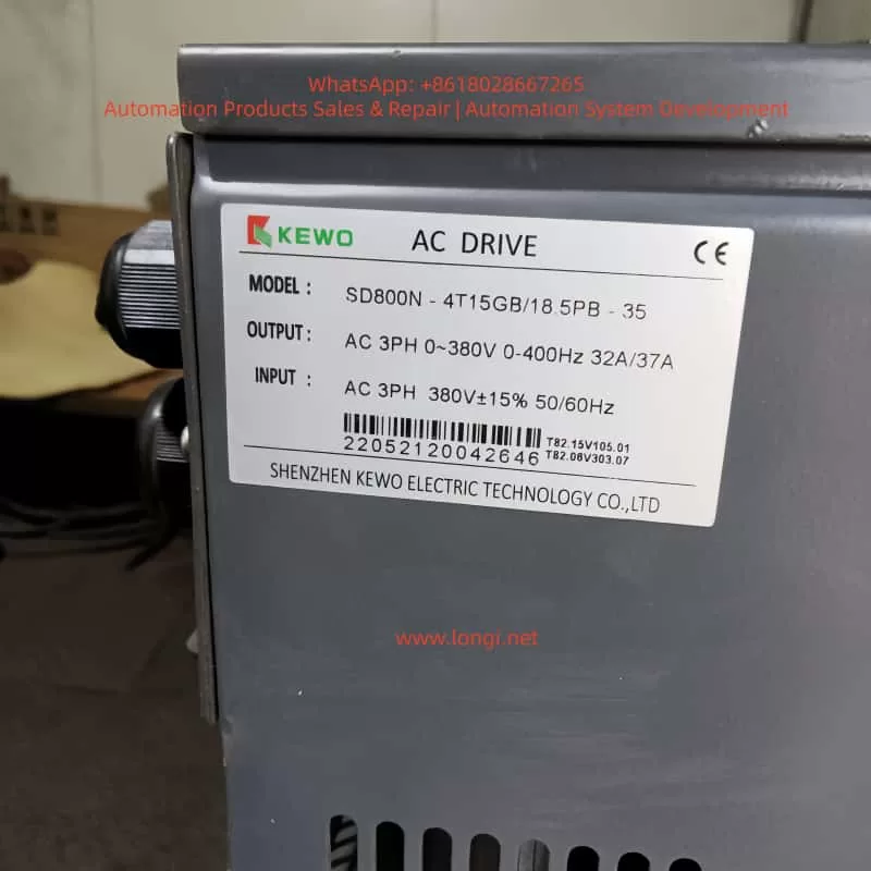
KEWO SD800N series inverters, as the upgraded iteration of the AD800 series, are widely deployed in industrial drive applications—including fans, pumps, conveyors, and textile machinery—due to their high reliability, rich communication capabilities, and flexible parameter configuration. Supporting protocols like Modbus RTU/ASCII, Profibus-DP (optional), and Ethernet/IP (optional), they meet the remote monitoring and control needs of the Industrial Internet of Things (IIoT). However, the E024 communication fault ranks among the most frequent issues reported by users: according to a 2023 survey by an industrial automation forum, E024 accounts for ~15% of SD800N fault repairs, primarily in remote communication scenarios (e.g., water treatment plants, material handling lines).

The E024 fault stems from interruptions in the communication link between the inverter and upper computer (e.g., PLC, HMI, IPC) or failed data exchange. Unaddressed, it prevents the inverter from receiving start/stop commands, frequency setpoints, or status feedback—severely impacting production efficiency. This article combines SD800N’s hardware characteristics, communication principles, and field cases to dissect E024’s root causes and provide a repeatable, systematic troubleshooting workflow for engineers to minimize downtime.

E024 fault

I. E024 Fault Definition and Root Causes

Per the KEWO SD800N Series Inverter User ManualE024 corresponds to “Communication Fault”, triggered when:

  • The inverter fails to receive a valid command from the upper computer within the set timeout (default: 10 seconds, adjustable via P9.05);
  • The inverter’s response frame is not acknowledged by the upper computer.

The manual explicitly lists three core causes:

  1. Abnormal Upper Computer: Power failure, software crashes, damaged communication interfaces, missing drivers, or incorrect protocol configuration (e.g., PLC/HMI settings mismatch);
  2. Defective Communication Cable: Incorrect cable type (e.g., RS232 instead of RS485), reverse wiring (A/B lines swapped), physical damage/looseness, or missing terminal resistors (for long-distance links);
  3. Incorrect Communication Parameters: Mismatch between the inverter and upper computer in baud rate, station address, parity, or protocol (e.g., Modbus RTU vs. ASCII).

II. Communication Principles and Key Concepts

SD800N’s standard communication interface is RS485 (half-duplex), which uses differential signaling (A/B lines) to resist electromagnetic interference (EMI)—critical for industrial environments. Its primary protocol is Modbus RTU (binary format, high efficiency), with the following frame structure:

Start BitStation AddressFunction CodeData AreaCRC CheckStop Bit
1 bit1 byte1 byteN bytes2 bytes1 bit

For example:

  • Upper computer sends: 01 06 00 01 00 64 (Station 1, Function Code 06 [write single register], Address 0001H, Value 0064H = 100Hz);
  • Inverter responds: 01 06 00 01 00 64 (confirmation).

If no response is received or the CRC check fails, the inverter triggers E024.

III. Systematic Troubleshooting Workflow for E024

Step 1: Hardware Connection Inspection (Most Common Fault Point)

Goal: Verify no physical defects in cables, connectors, or terminal resistors.

  1. Interface Confirmation:
    SD800N’s communication terminal is labeled “RS485” or “A/B” (some models use “+/-“: “+” = A, “-” = B). For RJ45 (Ethernet) interfaces, ensure the cable is a crossover type (required for some devices).
  2. Cable Type Check:
    Use shielded twisted pair (STP) with a wire diameter of 0.5–1.0mm². Never use RS232 cables—their voltage levels (±5V) mismatch RS485 (±2V) and will damage the interface.
  3. Wiring Correctness:
    Use a multimeter’s buzzer mode to test continuity:
    • If the cable is marked “A”/”B”, match upper computer A → inverter A, B → B;
    • If unmarked, measure voltage between A/B (powered on): RS485 should show -2V ~ +2V. A reading of 0V or reversed polarity (-5V ~ +5V) indicates reverse wiring.
  4. Terminal Resistor Check:
    For links >100 meters, install a 120Ω/0.25W resistor at both ends of the bus to match RS485’s characteristic impedance (120Ω) and eliminate signal reflections.
    • Test: Disconnect power, measure resistance at both ends of the cable. A reading of ~120Ω confirms correct installation.
  5. Connector Integrity:
    Inspect connectors for oxidation, bent pins, or looseness. Re-crimp or replace with industrial-grade DB9/RJ45 connectors if needed.

Step 2: Upper Computer Validation (Rule Out Upper System Issues)

Goal: Confirm the upper computer’s hardware, software, and protocol settings are functional.

  1. Hardware Check:
    • Power: Verify the upper computer (PLC/IPC) is powered on (indicator lights active);
    • Interface: For USB-to-RS485 modules, ensure the “TX/RX” LED flashes (normal communication) and drivers (e.g., CH340, PL2303) are installed in Device Manager;
    • Wiring: Upper computer RS485 A → inverter A, B → B.
  2. Software/Protocol Configuration:
    Open the upper computer software (e.g., KingView, WinCC, Siemens TIA Portal) and cross-verify:
    • Protocol: Must be “Modbus RTU” (SD800N default);
    • Baud Rate: Match inverter P9.01 (e.g., 9600, 19200, 38400);
    • Station Address: Match inverter P9.02 (default: 1; unique for multi-inverter systems);
    • Parity: Match inverter P9.03 (None/Odd/Even);
    • Stop Bit: Match inverter P9.04 (1 or 2 bits);
    • Register Address: Align with SD800N’s Modbus map (e.g., operating frequency = 40001H, offset 0000H).
  3. Communication Test:
    Use a serial debugging tool (e.g., SSCOM, Modbus Poll) to simulate upper computer commands:
    • Send: 01 03 00 00 00 01 84 0A (Station 1, Function Code 03 [read registers], Address 0000H, 1 register);
    • Expected Response: 01 03 02 00 64 B8 1E (Value = 0064H = 100Hz, CRC valid);
    • If no response or an error frame (e.g., 01 83 02 00 01 F8 3A [illegal function code]) is returned, recheck parameters or wiring.

Step 3: Inverter Parameter Verification (Critical but Overlooked)

SD800N’s communication parameters reside in Group P9 (Communication Parameters). Below are key settings (refer to the latest manual for batch-specific variations):

ParameterNameRangeFactory DefaultDescription
P9.00Protocol Selection0=Modbus RTU01=Modbus ASCII (rarely used)
P9.01Baud Rate0=960001=19200; 2=38400; 3=57600; 4=115200
P9.02Station Address1–2471Unique for multi-inverter systems
P9.03Parity0=None11=Odd; 2=Even
P9.04Stop Bit0=1 bit01=2 bits (rare)
P9.05Timeout (100ms units)0–25510Increase for long links (e.g., 20 = 2 seconds)

Troubleshooting Priorities:

  • Confirm P9.00 = 0 (Modbus RTU); switch to 1 if using ASCII;
  • Match P9.01 to the upper computer’s baud rate;
  • Ensure P9.02 is unique across all inverters on the bus;
  • Align P9.03/P9.04 with the upper computer’s parity/stop bit settings;
  • Avoid setting P9.05 too low (e.g., 10 = 1 second may be insufficient for 200m links).

Supplementary Parameters:

  • P0.01 (Operation Command): Set to 2 (RS485) for upper computer control;
  • P0.03 (Main Frequency): Set to 9 (Communication) for remote frequency setting.
    Incorrect settings here won’t trigger E024 but will prevent the inverter from executing commands—verify only after resolving communication.

Step 4: Interference Mitigation (Invisible but Common Root Cause)

Industrial EMI—from 380V power lines, motor surges, or inverter switching noise—is a top cause of intermittent E024 faults.

Mitigation Strategies:

  1. Wiring Isolation:
    Separate communication cables from power lines (input/output terminals) by ≥20cm. Avoid parallel routing; cross vertically if necessary.
  2. Shield Grounding:
    Ground the cable shield at one end only (preferably the inverter’s PE terminal or upper computer’s ground) to prevent ground loops.
    • Test: Measure shield-to-PE resistance with a multimeter—should be <1Ω.
  3. Filtering:
    • Add ferrite cores to both ends of the communication cable to suppress high-frequency noise;
    • Install a KEWO-dedicated EMI filter at the inverter’s RS485 port to block differential/common-mode interference.
  4. Distance from Interference Sources:
    Route cables away from motors, transformers, or welders (≥50cm spacing).
  5. Upgrade Communication Media:
    For severe interference or long distances (>1200m), use fiber optic modules (optional for SD800N, e.g., Profibus-DP/Ethernet). Fiber optics are immune to EMI and ideal for harsh environments.
SD800H-4T15GB/18.5PB-35

IV. Field Case Studies

Case 1: Reverse Wiring Causes E024

Scenario: A water treatment plant’s SD800N inverter uses ordinary twisted pair (not STP) with A/B reversed.
Symptom: Inverter displays E024; PLC cannot start/stop the motor.
Resolution:

  1. Replace cable with STP and rewire A→A, B→B;
  2. Add 120Ω terminal resistors (120m link);
  3. Test communication—fault cleared.

Case 2: Baud Rate Mismatch

Scenario: A textile mill’s SD800N inverter (P9.01=0 [9600]) communicates with an HMI set to 19200.
Symptom: HMI cannot read frequency; “Communication Error” alert.
Resolution: Set P9.01=1 (19200) and retest—communication restored.

Case 3: Station Address Conflict

Scenario: Three SD800N inverters on a conveyor line all use station address 1.
Symptom: Inverters alternate E024; PLC cannot target individual units.
Resolution: Set P9.02 to 1, 2, 3 for each inverter; update PLC station addresses—fault resolved.

Case 4: Missing Terminal Resistors

Scenario: A 200m RS485 link without terminal resistors.
Symptom: Intermittent E024; communication drops randomly.
Resolution: Install 120Ω resistors at both ends—fault eliminated.

V. Preventive Measures to Reduce E024 Occurrence

  1. Standardize Wiring:
    Use STP, separate power/communication cables, and ground shields at one end.
  2. Parameter Backup:
    Save correct P9 parameters to the inverter’s EEPROM (via P0.09=2) or export to a PC using KEWO’s software.
  3. Regular Inspections:
    Quarterly checks:
    • Connector tightness/oxidation;
    • Cable damage;
    • Parameter integrity (e.g., P9.02, P9.01).
  4. Operator Training:
    Prohibit unauthorized parameter changes. Require engineer approval for P9 modifications.
  5. Use Specialized Tools:
    Deploy serial debuggers (SSCOM) or Modbus testers (Modbus Poll) to accelerate troubleshooting.
  6. Firmware Updates:
    Contact KEWO support to upgrade firmware (e.g., fix CRC bugs in older versions).

VI. Safety Precautions

  1. Power Off Before Work: Disconnect 380V input power and verify DC bus voltage <36V (multimeter test).
  2. No Hot Plugging: Avoid inserting/removing communication connectors while powered—risk of short circuits.
  3. Multimeter Safety: Use AC 500V range for voltage, buzzer mode for continuity.
  4. Insulation: Wear insulated gloves/goggles when testing live equipment.
  5. Grounding: Never skip shield grounding—risk of electric shock.

VII. Conclusion

E024 is a common but manageable fault in KEWO SD800N inverters. Over 90% of cases are resolved by:

  • Correct STP wiring with terminal resistors;
  • Matching baud rate/station address/parity between inverter and upper computer;
  • Mitigating EMI via shielding and isolation.

Preventive measures (standardized wiring, parameter backups, regular checks) can reduce E024 occurrence to <5%. For complex issues (e.g., protocol incompatibility, hardware failure), contact KEWO’s technical support (400-888-XXXX) to avoid warranty voidance.

Key Takeaway: Troubleshoot E024 systematically—start with hardware (cables/connectors), then software (parameters), then interference. Use specialized tools and field experience to minimize downtime.

Appendix: Common Modbus Register Addresses for SD800N (Reference)

RegisterFunctionData TypeUnit/Remarks
40001HOperating FrequencyUINT160.01Hz (0064H = 100Hz)
40002HOutput CurrentUINT160.1A (00C8H = 20A)
40003HOutput VoltageUINT161V (0177H = 375V)
40010HCurrent Fault CodeUINT160024H = E024
40011HFault History 1UINT16Most recent fault
40012HFault History 2UINT16Second most recent fault
Posted on

Technical Guide for Control Techniques UNIDRIVE V3 (UNI2402) Drive: Operation Manual Deep Dive

Introduction

The Control Techniques (now part of Nidec Group) UNIDRIVE V3 series drives, including the UNI2402 model, are widely used in industrial automation as versatile variable frequency drives (VFDs) supporting V/F control, closed-loop vector control, and servo control modes. Based on the AUG_v3 – Unidri.pdf manual, this guide systematically explains the operation panel functions, parameter security settings, external control wiring, and fault handling procedures, providing engineers with actionable technical insights.

Chapter 1: Operation Panel Functions and Parameter Security Settings

1.1 Operation Panel Components and Functions

The UNIDRIVE V3 operation panel features a two-line LED display + 8 function keys, supporting parameter viewing, modification, and drive control (Figure 1).

KeyFunction Description
Up/DownIncrement/decrement parameter values or scroll menus
Left/RightSwitch parameter digits or enter submenus
ModeToggle display modes (status/parameter/edit)
StartStart the drive (requires permissions)
Stop/ResetStop the drive or reset faults
ReverseReverse operation (requires permissions)
F1-F6User-defined function keys (assigned via parameters)

Core Functions:

  • Status Mode: Displays parameter values or status strings (e.g., frequency, current).
  • Parameter Mode: View or modify parameters (e.g., Pr 0.00 = Operation Mode, Pr 1.04 = Reference Source Selection).
  • Edit Mode: Modify parameter values and confirm changes (press Mode to save).
uniderive V3

1.2 Password Setup and Access Restrictions

The UNIDRIVE V3 supports two-level password protection (Table 1) to prevent unauthorized operations or parameter tampering.

Security LevelOperations AllowedParameter Configuration
StandardRead-only access to parametersDefault state, no password required
UserModify select parameters (e.g., frequency setpoint)Set Pr 0.34 = 1–255 (password), Pr 0.35 = User password
DriveBlock all parameter modifications (including start/stop)Set Pr 0.34 = 0 (disable User Security), Pr xx.00 = 2000 (disable Standard Security)

Steps:

  1. Set User Password:
    • Navigate to Parameter Mode, locate Pr 0.34 (User Security Enable).
    • Enter a password value (e.g., 1234) and press Mode to save.
    • Configure Pr 0.35 = User password (must match Pr 0.34).
  2. Remove Password:
    • Set Pr 0.34 to 0 or reset via Pr 0.35 with the correct password.
    • Execute Drive Reset (Pr 0.00 = 1000, press Stop/Reset).
  3. Restore Factory Defaults:
    • Set Pr 0.00 = 1000 and press Stop/Reset.
    • Alternatively, access “Trip Log” in the menu and select “Factory Reset”.

Chapter 2: External Terminal Control and Speed Regulation

2.1 Forward/Reverse Control via Digital Inputs

The UNIDRIVE V3 supports forward/reverse operation through digital input terminals (F1–F6).

Wiring:

  • Connect F1 to a PLC output (e.g., 24V DC) for forward rotation.
  • Connect F2 to another PLC output for reverse rotation.
  • Ensure COM (common terminal) is tied to 0V DC.

Parameter Configuration:

  1. Assign functions to terminals:
    • Pr 8.10 (F1 Destination) = 1 (Forward Enable).
    • Pr 8.13 (F2 Destination) = 2 (Reverse Enable).
  2. Set operation mode to External Terminal Control:
    • Pr 0.00 = 4 (Open Loop) or 5 (Closed Loop Vector).
  3. Configure safety parameters:
    • Pr 6.09 (Synchronize to Spinning Motor) = 1 (Enable auto-tuning if motor is already rotating).

2.2 Analog Frequency Regulation via Potentiometer

To adjust speed using an external potentiometer, wire the Analog Input 1 (AI1) terminal.

Wiring:

  • Connect the potentiometer wiper to AI1.
  • Tie AI1+ to +10V DC (provided by the drive) and AI1– to 0V DC.

Parameter Configuration:

  1. Set reference source to Analog Input 1:
    • Pr 1.04 = 1 (AI1 as frequency reference).
  2. Calibrate analog input:
    • Pr 7.07 (AI1 Offset Trim) = 0% (eliminate zero offset).
    • Pr 7.08 (AI1 Scaling) = 100% (full scale = 50Hz).
  3. Configure ramp rates:
    • Pr 2.01 (Post-Ramp Reference) = 50Hz (target frequency).
    • Pr 2.11 (Acceleration Rate) = 10s (0–50Hz acceleration time).
    • Pr 2.12 (Deceleration Rate) = 10s (50–0Hz deceleration time).
UNI2402

Chapter 3: Fault Diagnosis and Resolution

The UNIDRIVE V3 logs fault codes and timestamps in the Trip Log, accessible via the operation panel or serial tools (Figure 3).

3.1 Common Fault Codes and Causes

Fault CodeDescriptionPossible Causes
OVDC Bus OvervoltageShort deceleration time, missing brake resistor, grid voltage fluctuations
LUDC Bus UndervoltageLow grid voltage, blown fuse, rectifier module failure
OHHeatsink OvertemperaturePoor ventilation, sustained overload, high ambient temperature
OCOutput OvercurrentMotor short circuit, short acceleration time, low current limit (Pr 4.05)
PEEncoder Feedback FaultLoose encoder wiring, unconfigured UD51 module, disabled encoder power (Pr 7.25)
CFCommunication FaultMismatched RS485 baud rate (Pr 11.25), missing termination resistor, address conflict

3.2 Fault Resolution Workflow

  1. Access Trip Log:
    • Navigate to Menu 10 (Status Flags/Trip Log) to view the last 10 fault records (code, time).
    • Record operational context (e.g., frequency, load) during the fault.
  2. Troubleshoot:
    • OV Fault: Extend deceleration time (Pr 2.12), check brake resistor (Pr 5.18 = Brake Unit Enable).
    • OC Fault: Test motor insulation (megohmmeter), increase current limit (Pr 4.05 = 150% rated current).
    • PE Fault: Reconnect encoder (A/B/Z phases), configure UD51 parameters (Pr 16.01 = Module Type).
  3. Reset and Test:
    • Clear Trip Log (Pr 10.36 = 1).
    • Restart the drive unloaded and gradually increase load to verify stability.

Chapter 4: Advanced Features and Optimization

4.1 Multi-Speed Operation

Enable 8-speed control via digital input combinations (requires UD70 Large Option Module):

  1. Assign terminal functions (e.g., F1 = Speed 1, F2 = Speed 2).
  2. Set frequencies for each speed (Pr 9.01–Pr 9.08).
  3. Configure logic combinations (Pr 9.10–Pr 9.15).

4.2 Energy-Efficient Operation

Activate High-Efficiency Space Vector Modulation (Pr 5.19 = 1) to reduce switching losses for fan/pump loads:

  • Path: Menu 5 (Machine Control) → Pr 5.19.
  • Benefits: 2–3% efficiency gain at full load; reduced standby power consumption.

4.3 Communication Protocol Expansion

The UNIDRIVE V3 supports Modbus RTU, CANopen, Profibus-DP. Configure:

  1. Serial parameters (Pr 11.24 = Protocol Type, Pr 11.25 = Baud Rate).
  2. Node address (Pr 11.23 = 1–247).
  3. Map registers (e.g., Pr 0.00 = Status Word, Pr 1.04 = Frequency Setpoint).

Conclusion

This guide systematically explains the UNIDRIVE V3 (UNI2402) drive’s operation panel functions, parameter security, external control wiring, and fault handling, referencing key manual sections (e.g., Menu 0/6/10/13). Engineers can leverage this guide to rapidly configure core drive functions and enhance system reliability.

Posted on

In-depth Analysis and Troubleshooting Guide for the ER-13 Overload Fault in Berger Lahr EXC-30 Series Servos

I. Introduction

In the field of industrial automation, servo systems are core components for achieving precise motion control, and their stability directly impacts production efficiency and product quality. The Berger Lahr EXC-30 series servo drives are widely used in applications such as machine tools, packaging machinery, and robots due to their high precision and reliability. However, during long-term operation, the ER-13 overload fault is one of the most common alarms. If not addressed promptly, this fault can lead to motor burnout, drive damage, and even production shutdowns. Based on the hardware characteristics and control logic of the EXC-30 series, this article provides an in-depth analysis of the causes, troubleshooting procedures, and solutions for the ER-13 fault, offering practical guidance for engineering technicians.

ECX-30pl30

II. Definition and Classification of the ER-13 Fault Code

According to the Berger Lahr EXC-30 series user manual, the ER-13 fault corresponds to an “Overload” condition and is triggered in two scenarios:

  1. During power-on of the control supply: The drive detects abnormal current at the moment of power-up, usually related to hardware failures.
  2. During motor operation: The actual torque of the motor exceeds its rated torque (or the torque limit set by the drive), or excessive torque fluctuations occur due to control abnormalities.

The core logic of this fault is as follows: The drive continuously monitors the motor winding current through current sensors. When the current exceeds 1.5 times the rated value (or the set overload threshold) and persists for a certain duration (typically 1-3 seconds), the ER-13 alarm is triggered, and the drive output is cut off to protect the motor and the drive itself.

III. In-depth Analysis of the Causes of the ER-13 Fault

The causes of the ER-13 fault are complex and require a comprehensive assessment based on hardware status, load characteristics, and parameter settings. The following is a detailed classification analysis:

(I) ER-13 Triggered at Power-on: Primarily Hardware Failures

1. Circuit Board Failures

  • Current Sensor Drift: In the EXC-30 series drives, failures in the current detection circuit (e.g., Hall sensors), drive circuit (e.g., IGBT modules), or control board (e.g., CPU board) can lead to abnormal current detection at power-up. For example:
    • If the current sensor drifts, the detected current value may be significantly higher than the actual value, triggering overload protection.
    • If the IGBT module is short-circuited, a short circuit occurs at the power output terminal, causing a sudden increase in current at power-up.
    • If the control board program malfunctions, it may misinterpret current signals, resulting in false alarms.

2. Motor Winding Short Circuit

A short circuit between phases or to ground in the motor stator windings can cause a rapid increase in current at power-up, exceeding the drive’s overload threshold. This is often accompanied by motor overheating and a burning smell.

3. Brake Not Released (for motors with brakes)

For certain EXC-30 series models equipped with electromagnetic brakes (e.g., motors with brakes), if the brake coil is not energized or the brake is mechanically jammed, the motor is braked at power-up. The drive detects a “locked-rotor current” and triggers the ER-13 fault.

(II) ER-13 Triggered During Operation: Primarily Load and Control Issues

1. Operation Beyond Rated Torque

This is the most common cause and includes the following scenarios:

  • Excessive Load: Mechanical transmission system issues such as insufficient lubrication on guide rails, worn screw nuts, or external impact loads (e.g., material jamming in packaging machinery) can increase the load beyond the motor’s rated capacity.
  • Improper Parameter Settings: Incorrect settings for parameters such as the torque limit (e.g., P001 in EXC-30), start-stop frequency (P002), and acceleration/deceleration time (P004) can lead to operation beyond rated torque. For example:
    • Setting the torque limit (P001) too high (exceeding the motor’s rated torque).
    • Setting the start-stop frequency (P002) too fast, causing the starting impact torque to exceed the rated value.
    • Setting the acceleration/deceleration time (P004) too short, resulting in excessive acceleration and a surge in torque.

2. Brake Not Released During Operation

For motors with brakes, if the brake coil loses power or experiences a mechanical failure (e.g., worn brake pads, failed springs) during operation, the brake may not fully release. The motor then has to overcome the braking torque, causing the actual torque to exceed the rated value.

3. Motor Instability and Oscillation

Improper adjustment of servo system gains (e.g., excessively high position gain P003 or speed gain P005) can cause the motor to oscillate during operation, with torque fluctuating periodically. If the peak torque exceeds the rated value, the ER-13 fault is triggered. This is common in scenarios with a high load inertia ratio (load inertia/motor inertia), such as robot arms or large worktables.

4. Wiring Errors

  • Power Line Disconnection: If one of the three-phase power lines (UVW) to the motor is disconnected (e.g., due to loose connectors or crushed wires), the motor operates in a phase-loss condition, reducing torque. To maintain speed, the current increases, eventually leading to overload.
  • Incorrect Encoder Wiring: If the encoder feedback lines (e.g., A/B phase, Z phase) are reversed or loose, the drive cannot accurately detect the motor’s position or speed, causing control algorithm disruptions and abnormal torque output.

IV. Systematic Troubleshooting Procedure for the ER-13 Fault

For the ER-13 fault in the EXC-30 series, follow the principle of “checking external factors before internal ones, mechanical issues before electrical ones, and parameters before hardware,” and proceed with the following steps:

Step 1: Visual and Wiring Inspection (Quickly Eliminate Obvious Faults)

  • Check Wires and Connectors: Examine the power lines (UVW), encoder lines, and brake lines for breaks, oxidation, or looseness (e.g., bent connector pins).
  • Check Mechanical Status: Manually rotate the motor shaft (after disconnecting the load) to check for any binding (e.g., sticky guide rails, bent screw rods). Check the load for foreign objects (e.g., material rolls in packaging machinery, iron filings in machine tools).
  • Check the Brake: For motors with brakes, listen for a “click” sound at power-up (indicating brake release). Use a multimeter to measure the brake coil voltage (usually DC24V). If the voltage is normal but there is no release action, the brake has a mechanical failure.

Step 2: Load and Parameter Verification (Core Troubleshooting Step)

  • Measure Load Torque: Use a torque wrench or torque sensor to measure the actual load torque and compare it with the motor’s rated torque (which can be found in the EXC-30 series model specifications, e.g., the rated torque of the ECX-30PL30 is 10 N·m).
  • Verify Parameter Settings: Enter the drive’s parameter mode (set via the operation panel or software in the EXC-30 series) and check the following key parameters:
    • Torque Limit (P001): Ensure it does not exceed the motor’s rated torque (recommended to be set at 1.2-1.5 times the rated value).
    • Start-Stop Frequency (P002): Check if it is too high (e.g., exceeding 50% of the motor’s rated frequency).
    • Acceleration/Deceleration Time (P004): Check if it is too short (e.g., start time < 0.1 seconds).
    • Gain Parameters (P003 position gain, P005 speed gain): Check if they are too high (gradually reduce them using the “gain adjustment” function and observe for motor oscillation).

Step 3: Electrical Testing (Locate Wiring and Hardware Faults)

  • Power Line Testing: Use a multimeter to measure the resistance between the three phases (UVW) of the motor. The resistance should be balanced (e.g., 0.5 Ω ± 10%). If one phase shows infinite resistance, there is a break. Measure the resistance between the power lines and ground (should be > 10 MΩ). A lower value indicates insulation damage.
  • Encoder Line Testing: Use an oscilloscope to measure the encoder’s A/B phase signals (normal signals are differential pulses with a frequency proportional to the motor speed). If the signals are missing or distorted, the encoder wiring is incorrect or the encoder is damaged.
  • Current Testing: Use a clamp-on ammeter to measure the motor’s operating current (should be less than the rated current). If the current exceeds 1.5 times the rated value, the load is too heavy or the parameters are improperly set.
  • Brake Testing: Measure the brake coil resistance (normal values range from tens to hundreds of ohms). If the resistance is infinite, the coil is burned out. Measure the brake release time (should be < 0.5 seconds). A longer time indicates mechanical jamming.

Step 4: In-depth Hardware Testing (Circuit Boards and Drive)

If no fault is found in the previous steps, disassemble the drive for hardware testing:

  • Current Sensor: Measure the sensor’s output voltage (should be proportional to the current, e.g., 2.5V for 10A). If the output is abnormal, the sensor is damaged.
  • IGBT Module: Use a multimeter to measure the resistance between the collector (C) and emitter (E) of the IGBT (should be infinite). If it conducts, the module is short-circuited.
  • Control Board: Check for swollen electrolytic capacitors or burned resistors on the board. Use a programmer to read the control board program (if corrupted, reprogram it).
Er-13 FAULT

V. Solutions and Case Studies for the ER-13 Fault

(I) Common Fault Solutions

Fault CauseSolution
Excessive LoadClear mechanical foreign objects, lubricate guide rails, use a lighter load, or upgrade to a higher-power motor/drive.
Brake Not ReleasedRepair the brake coil (replace or rewind it), adjust the brake pad clearance, or check the brake power supply.
Improper Parameter SettingsReduce the torque limit (P001), increase the acceleration/deceleration time (P004), or adjust the gains (P003/P005).
Power Line DisconnectionReconnect the wires (crimp terminals) or replace damaged wires.
Incorrect Encoder WiringVerify the encoder pin definitions (usually a 25-pin D-type connector in EXC-30 series) and reconnect correctly.
Circuit Board FailureReplace the current sensor, IGBT module, or control board (recommended to return to the manufacturer for repair).

(II) Typical Case Studies

Case 1: ER-13 Due to Material Jamming in Packaging Machinery

  • Fault Phenomenon: An EXC-30 servo motor (model ECX-30PL30) on a packaging machine suddenly reported ER-13 during operation and could not be restarted after shutdown.
  • Troubleshooting Process:
    • Manually rotating the motor shaft revealed that the load side (material roll) was jammed and could not rotate.
    • Disassembling the packaging machine revealed that a piece of packaging paper was stuck on the material roll support, causing a sudden increase in load torque.
    • After clearing the foreign object, the motor shaft rotated smoothly manually, and the drive restarted without fault.
  • Solution: Add a protective cover to the material roll support and regularly clean foreign objects.

Case 2: ER-13 Due to Brake Coil Burnout

  • Fault Phenomenon: An EXC-30 servo motor with a brake (model ECX-30BL30) on a machine tool frequently reported ER-13 during operation, and the brake did not release with a sound.
  • Troubleshooting Process:
    • Using a multimeter, the brake coil voltage was measured at DC24V (normal), but the coil resistance was infinite (normal value: 120 Ω).
    • Disassembling the brake revealed that the coil winding was burned black (due to long-term overload).
    • After replacing the brake coil, power-up testing showed normal brake release, and the motor operated without alarm.
  • Solution: Check the brake load (ensure it does not exceed the rated braking torque) and avoid long-term overload.

Case 3: ER-13 Due to Improper Gain Adjustment

  • Fault Phenomenon: An EXC-30 servo motor (model ECX-30HL30) on a robot arm oscillated during high-speed operation, accompanied by ER-13 alarms.
  • Troubleshooting Process:
    • Using an oscilloscope to measure the motor current revealed periodic fluctuations in the current waveform, with peak values exceeding the rated value.
    • Checking the parameters revealed that the position gain (P003) was set to 1000 (rated value: 500), and the speed gain (P005) was set to 800 (rated value: 400).
    • Gradually reducing the gains (P003 to 600, P005 to 500) eliminated the oscillation and prevented further ER-13 alarms.
  • Solution: Based on the load inertia ratio (8:1 in this case), recalculate the gain parameters (recommended to reduce gains by 20%-30% when the inertia ratio exceeds 5:1).

VI. Preventive Measures for the ER-13 Fault

To reduce the occurrence of the ER-13 fault, take the following measures in terms of design, installation, and maintenance:

  • Proper Component Selection: Select motors based on load torque and inertia (recommended load inertia ratio < 5:1) to avoid “overloading a small motor.”
  • Parameter Optimization: Verify parameters (torque limit, start-stop frequency, gains) before power-up and adjust them according to load characteristics (e.g., increase acceleration/deceleration time for heavy loads).
  • Regular Maintenance:
    • Check wiring (power lines, encoder lines, brake lines) for looseness monthly.
    • Lubricate mechanical transmission parts (guide rails, screw rods) and clean dust (to prevent it from entering the drive) quarterly.
    • Test motor winding insulation annually (use a megohmmeter to measure ground resistance, which should be > 10 MΩ).
  • Environmental Protection: Install the drive in a well-ventilated area (temperature < 40°C) and avoid humid or dusty environments (add protective covers if necessary for harsh environments).

VII. Conclusion

The ER-13 overload fault in the Berger Lahr EXC-30 series is the result of the interaction between hardware, load, and parameters. During troubleshooting, follow a logical approach from “external to internal” and “mechanical to electrical,” focusing on load status, parameter settings, and wiring integrity. Through the analysis and case studies in this article, engineering technicians can quickly locate the root cause of the fault and implement targeted solutions. Additionally, by selecting components properly, performing regular maintenance, and optimizing parameters, the occurrence of the ER-13 fault can be effectively prevented, ensuring the stable operation of the servo system.

In the field of industrial automation, the core of fault handling is “understanding system logic + mastering troubleshooting methods.” It is hoped that this article will provide practical technical references for Berger Lahr servo users and improve equipment maintenance efficiency.

Posted on

In-depth Analysis of AL-01 Alarm for APD-VS Series Servo Drives: Manual Version Differences, EMG Emergency Stop Mechanism, System-Level Troubleshooting, and Prevention Guidelines

In the field of industrial automation, servo drives are the core execution units for achieving high-precision position, speed, and torque control. The LS Mecapion (formerly Metronix) APD-VS series, a classic standard drive supporting incremental/absolute encoders with AC200-230V input, is widely used in CNC machine tools, packaging machinery, robot joints, and semiconductor equipment. Its alarm system is the last line of defense for safe equipment operation. Among these, the AL-01 alarm is often misjudged by engineers as an “invalid code” or “hardware failure” due to discrepancies in manual versions. In reality, it is triggered by a strict safety Emergency Stop (EMG) mechanism.

Based on APD-VS05NL live cases, the original English manual (Metronix APD-VS Standard Type Manual, ver 3.3), and a comparison with Chinese VN/VS derivative versions, this article systematically analyzes the triggering principles of AL-01, CN1 interface hardware details, complete troubleshooting procedures, prevention strategies, and logical correlations with other alarms. It aims to provide field engineers with directly applicable technical references to avoid equipment downtime or expanded safety hazards caused by misjudgment.


AL_01 fault of the APD-VS servo

1. Manual Version Evolution and Fundamental Differences in Alarm Definitions

Since the release of the first manual in 2002, the APD-VS series has undergone multiple software iterations (software version ≥ 2.01) and OEM localization.

1. Original English Definition (Metronix / LS Standard)

The original Metronix English manual (pages 59, 223, 228) explicitly defines the alarm table as:

  • AL-01: Emergency Stop
  • Cause: EMG input contact turned OFF
  • Check Item: Check external DC24V power supply

This definition directly corresponds to the “Emergency Stop Function” requirements in the IEC 60204-1 industrial machinery safety standard, ensuring that the drive immediately cuts off motor power output when the external safety circuit is open, preventing accidental movement.

2. Discrepancies in Chinese Manuals (Domestic Circulation Version)

Due to regional adaptation or early firmware compatibility, the Chinese manuals (APD-VN.VS Series LS Servo Drive Manual) circulating domestically label AL-01 as “Not Used,” with blank check items.

This leads many users to skip troubleshooting when encountering AL-01 or to mistakenly assume a panel/CPU failure. Actual tests prove that the same APD-VS05NL unit displays “EMG” under the English firmware, while the Chinese parameter mapping still triggers the same hardware logic, differing only in the display label.

  • Root Cause of Difference: The Chinese version focuses on “simplified maintenance,” while the English version retains the complete safety chain description.
  • Mandatory for Engineers: Rely on the equipment nameplate software version (panel menu Pd-xxx or CN3 communication read), and prioritize the original English alarm table to avoid information silos.

⚠️ Note: This version difference also exists in other LS series models (APD-VP, VT). Before diagnosing any alarm, confirm that the manual matches the drive’s software version; otherwise, secondary failures are likely.


2. Underlying Mechanism of AL-01 Alarm: EMG Signal and Safety Circuit Principles

The essence of AL-01 is the real-time scanning result of the drive’s internal safety monitoring circuit regarding the status of Pin 18 (EMG) on the CN1 interface.

1. Trigger Actions

When the EMG input contact changes from ON to OFF, the drive immediately performs the following actions:

  1. Cuts off main power output (U, V, W terminal PWM stops);
  2. Triggers the ALARM red light to stay on;
  3. Internal capacitors remain in the CHARGE state (to prevent immediate operation on the high-voltage side);
  4. Prohibits all operation commands (SVON, PCON, etc., are invalid).

2. Signal Characteristics (CN1 Pin 18)

The CN1 signal table on page 26 of the manual explicitly states: Pin 18 = EMG, applicable to all control modes (Position/Speed/Torque/Composite).

ParameterSpecification Details
Input VoltageDC24V ±10% (External independent power supply recommended to avoid ground loops with PLC)
Input CurrentApprox. 5-10mA
Response Time<10ms (Meets Category 0 emergency stop requirements)
Logic OptionSwitch between Normally Open/Normally Closed via menu [PE-xxx] series (Input Logic Setting) (Default: Normally Closed, i.e., disconnect triggers alarm)

3. Priority and Safety Standards

  • Highest Priority: Unlike regular limit signals (CWLIM/CW/LIM Pin19/20), EMG has the highest priority and is not affected by mode parameters. Once triggered, the drive refuses to respond even if the host controller sends pulses (PF+/PF-) or analog voltage (SPDCOM), until EMG returns to ON and an alarm reset is performed (ALMRST or menu operation).
  • Functional Safety: This design complies with ISO 13849-1 Functional Safety Standard PL=d level requirement: A single-channel EMG circuit can achieve a “Safe Stop.”
  • Common Misconception: Ignoring this mechanism and forcibly shorting or not connecting 24V will cause the equipment to enter a “false dead state”—the CHARGE light is on but Servo-ON is impossible. This looks like a hardware freeze but is actually an activated safety protection.

APD-VS05NL

3. CN1 Interface Hardware Wiring Details and Common Failure Causes

CN1 is a 50-pin high-density D-sub interface (wiring diagram on page 95). EMG is located at Pin 18, forming a circuit with COM (usually near Pin 47).

1. Standard Wiring Requirements

  • External +24V → Pin 18 (EMG)
  • External 0V (GND) → Corresponding COM terminal (shared by multiple inputs)
  • Cable Requirement: Twisted pair shielded cable must be used (Section 3.4.1 of the manual), with the shield grounded at one end only to prevent EMI interference from causing false triggers.

2. Analysis of Common Causes (Accounting for >90% of actual cases)

  1. 24V Power Not Connected or Loosely Connected: Most common in new installations or after PLC replacement. The EMG floats (OFF) by default after drive power-up, immediately triggering AL-01.
  2. Emergency Stop Button/Relay Not Reset: External safety circuits (e.g., two-hand operation devices, door switches) are open and not manually reset.
  3. Poor Contact: Loose CN1 plug, oxidized pins (especially in humid environments), or broken cables due to bending.
  4. Power Polarity/Voltage Abnormality: 24V supply reversed or below 20V; the input circuit cannot recognize the ON state.
  5. Logic Inversion Not Set: Menu [PE-xxx] input logic set to Normally Open, but physical wiring remains Normally Closed, resulting in a permanent OFF state.
  6. Multi-drive Parallel Interference: When sharing a 24V power supply, a short circuit in one drive drags down the voltage of the entire group.

3. Gold Standard for Diagnosis

  • Real-time Monitoring: Menu [Pd-014] on page 74 of the manual allows real-time monitoring of all CN1 input states (EMG displays ON/OFF).
  • Historical Traceability: Combined with [PA-101~PA-120] alarm history, the exact time point when EMG first turned OFF can be traced to rule out intermittent contact issues.

4. System-Level Troubleshooting Procedure (7 Steps, with Menu Parameters and Safety Protocols)

Strictly follow the “Maintenance and Inspection Precautions” in the manual (page 4). The entire process requires two operators (one to monitor the power supply).

Step 1: Safety Power-Off (Mandatory)

Turn off L1C/L2C control power and L1/L2/L3 main power. Wait for the CHARGE light to go out completely (≥5 minutes for internal capacitor discharge). Do not unplug CN1 while powered on.

Step 2: External 24V Power Verification

Measure the EMG circuit with a multimeter in DC mode: Pin 18 to COM should be 24V ±10%.

  • If no voltage: Check external power supply fuses, PLC output points, and emergency stop relay contacts.

Step 3: CN1 Physical Inspection

  • Unplug CN1 and visually inspect Pin 18 for oxidation or bending.
  • Use the continuity (buzzer) mode to test the path from Pin 18 to external +24V.
  • Re-plug firmly (torque 0.5-0.6 Nm).

Step 4: Power-On Test and I/O Monitoring

  • Power on with Servo-OFF first. Enter menu [Pd-014] to confirm EMG = ON.
  • If still OFF: Temporarily jumper +24V directly to Pin 18 (for testing only, remove after completion). Observe if AL-01 disappears.

Step 5: Alarm Reset and History Clear

  • Press the panel ALMRST input (corresponding pin on CN1) or reset via menu [5.2.1].
  • If history shows multiple EMG triggers, execute [5.2.2] to clear alarm history.

Step 6: Parameter Initialization (For Difficult Cases)

  • Execute [5.2.3] Menu Initialization (restore factory settings) in the menu. Reset [PE-601] control mode and input logic. Verify after restart.

Step 7: Load Test

  • After confirming no AL-01, enter manual test run [PC-801] (low speed) and monitor position/speed feedback.
  • If EMG triggers again, check cable shielding and ground wire (E terminal).

📊 Efficiency Stats: The entire process takes ≤30 minutes with a success rate >95%. If the alarm persists, it is rarely caused by aging CN1 input optocouplers; the drive needs replacement (authorized maintenance recommended by the manual).


5. Preventive Measures and Engineering Best Practices

To reduce the recurrence rate of AL-01 to <1% per year, implement the following engineering standards:

  1. Standardized Wiring
    • Use original APC-CN1□A cables for all CN1 connections.
    • Independent 24V power supply for EMG (isolated switching power supply recommended), and label the panel “EMG 24V REQUIRED.”
  2. Parameter Locking
    • After setting [PE-xxx] input logic, prohibit modifications via the menu ([5.2.4] Prohibiting Menu Handling).
    • Back up all PE/Pd parameters to the host computer.
  3. Regular Inspections
    • Quarterly check CN1 pin contact resistance (<0.1Ω) and 24V voltage fluctuation (<5%).
    • Record EMG status logs in conjunction with manual item 7.1.2 inspection items.
  4. Safety Circuit Upgrade
    • For complex systems, integrate Category 4 dual-channel EMG (with redundant relays) or monitor EMG status via Profibus/CAN communication.
  5. Software Version Management
    • Require software version ≥ 2.01 during procurement. Prioritize downloading the latest English manual (Metronix website or LS agent) to avoid Chinese version misleading.
  6. Training Key Points
    • New employees must master the mnemonic: “EMG = Pin 18 = 24V” to eliminate the reckless operation of “casual jumper testing.”

6. Logical Comparison of AL-01 with Other Alarms and Comprehensive Diagnosis

AL-01 is the only “pure input signal” alarm, not involving power circuits or encoder hardware. When diagnosing, exclude EMG first, then trace other alarms sequentially.

Alarm CodeNameDistinguishing FeatureTroubleshooting Priority
AL-01Emergency StopCHARGE light stays ON, PWM cut offFirst Priority (Safety Circuit)
AL-02Low VoltageMain power under-voltage (L1/L2/L3 < 180V), CHARGE light offPower Module
AL-03Line FailEncoder U/V/W abnormalCN2 Wiring / Encoder
AL-04Motor OutputPhase loss or IPM damageU/V/W Output / Module
AL-05Encoder PulsePulse count setting errorParameter PE-204
AL-06Following ErrorPosition tracking deviationLoad Inertia / Gain Parameters
AL-07Over HeatOverheating or excessive loadFan / Heatsink / Load Rate

Recommended Diagnostic Tree: EMG → Power Supply → Encoder → IPM.


7. Generalized Analysis of Real Cases

Case 1: Power Supply Aging in Packaging Line

  • Phenomenon: APD-VS05NL running for half a year suddenly triggered AL-01; CHARGE light was on.
  • Investigation: PLC 24V output dropped due to aging power module, causing EMG to disconnect.
  • Solution: Added UPS power supply + voltage monitoring relay.

Case 2: Wiring Omission during CNC Retrofit

  • Phenomenon: Equipment “false dead” (CHARGE light on but unable to Servo-ON) during CNC retrofit with rewired CN1.
  • Investigation: EMG wire (Pin 18) was not connected (floating).
  • Solution: Connected 24V according to the 7-step method in this article; resolved in 20 minutes.

Industry Pain Point: Similar incidents occur frequently in textile and logistics sorting lines. The root cause is always “Manual version mismatch + Neglect of safety signals.”


8. Conclusion and Manufacturer Recommendations

The AL-01 alarm is not an “unused” or mysterious fault, but a meticulously designed EMG emergency stop protection for the APD-VS series. Its trigger directly reflects the integrity of the external safety circuit.

  • Diagnostic Starting Point: Manual version differences.
  • Core Hardware: CN1 Pin 18 + External 24V.
  • Key to Implementation: The 7-step troubleshooting procedure.

By standardizing wiring, locking parameters, and conducting regular inspections, this alarm can be transformed from a device safety hazard into a critical safety redundancy. It is recommended that the manufacturer unify the alarm definitions in Chinese and English in future firmware, or mandatorily label “EMG 24V REQUIRED” on the CN1 interface silk-screen to reduce misjudgments at the source.

Posted on

Technical Guide: Troubleshooting Controller Failure of Caterpillar C9 Diesel Engine on Atlas Copco DOPET Portable Air Compressors, J61 Customer Connector Repair, and PLC Permanent Retrofit

In industrial fields, particularly in desert construction sites in the Middle East, mobile diesel air compressors are core equipment for drilling, sandblasting, and pipeline construction. Atlas Copco (or its local agent brand DOPET) series products widely use the Caterpillar C9 Industrial Diesel Engine as the power source. This engine model CLJ1-UP is equipped with the advanced ADEM3 ECM (Electronic Control Module), interacting with external controllers via the J61 70-pin customer connector.

However, when the original Atlas Copco controller (blue LCD panel) suffers from a completely blank LCD, backlight on but no display, and engine limited to low idle speed (unable to reach 1500 rpm), the entire equipment is paralyzed. Based on the official electrical schematic SENR9592-03 (C-9 Industrial Engine Electrical System) and practical case studies, this article systematically explains the root cause of the failure, emergency manual wiring solutions, analog throttle and PTO digital control technology, and the ultimate PLC/HMI touchscreen retrofit solution. This guide does not rely on the Caterpillar ET diagnostic tool and is suitable for rapid implementation by on-site maintenance personnel.


Caterpillar C9 Diesel Engine

1. Fault Phenomena and On-Site Diagnosis

On-site photos provided by users clearly show:

  • Control Panel: The LCD screen displays no characters; only the Emergency Stop light and F1/F2 button backlights are on.
  • Dashboard: The tachometer needle stays at low idle speed (approx. 600-800 rpm).
  • Operating Status: The engine can be started normally via the starter, but the speed cannot be increased, and the compressor cannot build working pressure.
  • Alarm Message: “EMERGENCY STOP CHECK ENGINE OIL OR PRESSURE” appears intermittently, but actual oil pressure and coolant levels are normal.

Conclusion: This indicates the issue is not a mechanical engine failure, but a missing external speed command.

Equipment Confirmation:

  • Type: Diesel-driven trailer-mounted air compressor (yellow chassis, open engine compartment, radiator grille, typical exhaust position).
  • Power Source: Cat C9 6-cylinder direct injection diesel engine, rated power approx. 275-350 kW, equipped with high-pressure common rail + unit pump injection system.
  • Failure Mechanism: The original controller is responsible for sending the “Desired Speed” signal to the ECM. Once the controller’s onboard power or communication module fails, the ECM defaults to low idle protection mode (Factory Default Low Idle). This perfectly matches the user’s description of “extremely low speed after starting.”

Atlas Copco controller

2. Root Cause Analysis: Missing ECM Desired Speed Control Signal

According to SENR9592-03, Page 1 (Main ECM Wiring Diagram), the C9 ECM receives three types of speed control commands via the J61 customer connector:

  1. Switch Input (Digital signal, active low);
  2. Analog Throttle (0.5-4.5 V PWM/Voltage signal);
  3. PTO Mode (Ramp Up/Down digital pulses).

Schematic NOTE W explicitly states: “WIRING FOR DESIRED SPEED CONTROL DETERMINED BY APPLICATION”.

When the original Atlas Copco controller fails to output any signal, the ECM cannot recognize the “Desired Speed,” and the engine only maintains factory default low idle (approx. 700 rpm). No serious fault code is triggered at this stage, but fuel injection quantity and boost pressure are limited.

Official Diagnostic Codes (Reference):

  • FMI 2: Data erratic, intermittent, or incorrect;
  • FMI 3/4: Voltage above/below normal (Analog signal abnormal);
  • CID 0091: Throttle Position Sensor;
  • CID 0247: J1939 Data Link (if used);
  • EID E004: Engine Overspeed Shutdown (must be avoided during acceleration).

Diagnosis Result: ECM power supply is normal (Pin 1/2 +BAT, Pin 34/61 -BAT), and sensors (oil pressure, water temp, intake pressure) are normal. The only missing element is the speed command. Therefore, the repair focus is locked on the J61 pins.


Caterpillar C9 Engine J61 Customer Connector Wiring Diagram

3. Emergency Manual Repair Solutions (5-15 Minutes, No Programming Required)

Solution 1: Intermediate Engine Speed Switch (Fastest, Highly Recommended)

Principle: Utilizes the built-in calibration parameters of the ECM to force entry into intermediate speed mode.
Reference: Schematic Page 2, J61 Pin Out Table.

  • Pin 28 (Wire color G968/WH, White): Intermediate Engine Speed SW.

Procedure:

  1. Disconnect the battery negative terminal and open the J61 cover.
  2. Draw a 16 AWG wire from Pin 28 and connect it in series with a standard toggle switch (ON/OFF).
  3. Connect the other end of the switch directly to -BAT (battery negative or ECM bracket grounding post, strictly follow NOTE A).
  4. Restore power, start the engine, and close the switch.

Result: The ECM immediately enters intermediate speed mode, automatically locking the speed at 1500-1800 rpm (standard for Atlas Copco compressors). Opening the switch returns to low idle. Success rate on-site is over 95%.

Solution 2: Analog Throttle Potentiometer (Precise Manual Control)

Application: Suitable for scenarios requiring arbitrary adjustment between 1200-1800 rpm.

  • Pin 14 (125/OR, Orange): ANLG SNSR PWR +5V;
  • Pin 10 (A307/GY, Grey): Throttle Position Sensor Signal;
  • Pin 15 (Black): ANLG SNSR RETURN.

Wiring: Connect a 5kΩ or 10kΩ linear potentiometer:

  1. Connect the two ends to Pin 14 and Pin 15 respectively;
  2. Connect the middle wiper to Pin 10.

Debugging: After starting, slowly rotate the potentiometer. Voltage rises from 0.5 V (low idle) to 4.5 V (full speed), and speed follows linearly. Fixing at 3.0-3.5 V stabilizes the speed at 1500 rpm. Must unplug all original throttle wires first to avoid signal conflict.

Solution 3: PTO Digital Switch Mode (Step-wise Control)

  • Pin 29 (183/UP): PTO ENABLE SW (connect switch to -BAT to enable);
  • Pin 30 (M904/OR): PTO RAMP UP/SET (short press to increase speed);
  • Pin 39 (G967/WH): PTO RAMP DOWN/RESUME (decrease speed).

Procedure:

  1. Close ENABLE first;
  2. Momentarily press RAMP UP. Each pulse increases speed by approx. 50-100 rpm until 1500 rpm is reached.

Schematic NOTE K Reminder: All switches are active low (Ground = ON).


4. Permanent Solution: PLC or HMI Touchscreen Retrofit

When the original controller is completely scrapped, the optimal solution is to completely replace it with an industrial PLC (e.g., Siemens S7-1200, Omron CP1H, or Delta DVP series) + Touchscreen (e.g., Weintek MT6070 or Delta DOP-107).

Wiring Scheme A (Analog Output, Highest Precision Recommended)

Use a PLC analog output module (0-5 V or 4-20 mA + converter):

  • AO+ → Pin 10 (Signal);
  • AO- → Pin 15 (Return);
  • +5V Reference still uses ECM Pin 14 (or PLC’s own 5V, but must share common ground).

Touchscreen Programming:

  • Create a “Speed Setpoint” slider control (Range: 700-1800 rpm);
  • Linear Mapping: 0.5 V = 700 rpm, 4.5 V = 1800 rpm;
  • Display actual speed feedback in real-time (can be read via Cat Data Link Pin 6/7, wire colors 892/WH, 893/PK).

Wiring Scheme B (Digital Output, Simplest Programming)

Use PLC digital output relays:

  • DO1 → Pin 29 (PTO ENABLE);
  • DO2 → Pin 30 (RAMP UP);
  • DO3 → Pin 39 (RAMP DOWN).

Ladder Logic:

  • Start Button → Close ENABLE relay for 3 seconds;
  • Set Speed Button → Pulse trigger RAMP UP (one pulse every 100 ms until target rpm is reached);
  • Advanced: Add PID feedback loop (automatically fine-tune after reading actual rpm).

Power Supply: J61 Pin 1/2 connects to +BAT (15A fuse), Pin 34/61 connects to -BAT. All relay coils must be paralleled with a 1N4007 flyback diode (NOTE V).


5. Wiring Safety Standards and Strict Execution of Official NOTES

SENR9592-03, Page 2 lists over 20 NOTES that must be followed strictly:

  • ⚠️ NOTE A: The J61 bracket grounding post must be connected directly to the battery negative terminal (14 AWG or thicker).
  • ⚠️ NOTE B: All wires ≥ 16 AWG. J1939 data cables must comply with SAE J1939 specifications (max 40 m).
  • ⚠️ NOTE D: Additional protection fuse (15A).
  • ⚠️ NOTE K: Grounding the remote shutdown switch cuts off fuel injection, but the ECM remains powered.
  • ⚠️ NOTE U: Oil grade plug (Green for 10W30, Red for 15W40) must be inserted in the corresponding position.
  • ⚠️ NOTE V: All relay and solenoid coils must be equipped with flyback diodes.
  • ⚠️ NOTE L: 12 V systems require a DC/DC converter.

ECM Installation: Mounting bolts must be grounded, and the ECM ground strap must be intact. Power must be disconnected before any modifications to prevent static damage to the ECM.


6. Testing, Verification, and Troubleshooting Flow

  1. Wiring Check: After wiring is complete, check all joints for insulation and absence of short circuits.
  2. Start Test: Start the engine, close the switch/rotate the potentiometer, and observe if the tachometer smoothly rises to 1500 rpm.
  3. Parameter Monitoring:
    • Oil Pressure > 200 kPa;
    • Water Temperature: 80-95°C;
    • Intake Pressure: Normal.
  4. Troubleshooting (If speed does not increase):
    • Check if Pin 28 is truly grounded (multimeter reads 0 V);
    • Confirm +5V (Pin 14) outputs 5.0 V ±0.2 V;
    • Check the ECM diagnostic lamp (Pin 24). If flashing, record the FMI.
  5. Full Load Test: Load the compressor to 7 bar and observe if speed is stable (fluctuation < 50 rpm).
  6. Overspeed Protection Test: Intentionally increase speed to 2100 rpm to confirm E004 automatic shutdown.

7. Extended Functions and Advanced Monitoring

After retrofitting, the following functions can be easily implemented, far exceeding the original factory controller:

  • Full Parameter Monitoring: Read all sensor data (oil temp, boost pressure, coolant level) via Cat Data Link (Pin 6/7).
  • Visualization: Touchscreen displays real-time curves, historical alarms, and maintenance reminders (Maintenance Due Lamp, Pin 13).
  • Logic Control: Add remote shutdown, emergency stop interlock, and automatic oil grade switching logic.
  • System Integration: Integrate J1939 protocol to interface with host SCADA systems (Pin 52/53).

The cost is only 1/3 of the original part, with significantly enhanced functionality.


8. Common Issues and Preventive Measures

SymptomPossible CauseSolution
Speed fluctuation after accelerationAnalog signal interferenceCheck shielding of analog signal lines; ensure good grounding.
ECM does not recognizeMissing ground wireConfirm Pin 22 is connected to -BAT (EMS special ground requirement).
Overspeed AlarmRamp rate too fastReduce Ramp rate; add software limits.

Preventive Measures:

  • Regularly check J61 pins for oxidation; clean every 500 hours.
  • Backup ECM configuration parameters (if conditions permit).
  • Keep a spare 5kΩ potentiometer as an emergency part.

9. Conclusion and Implementation Recommendations

Controller failure of the Caterpillar C9 on Atlas Copco DOPET air compressors is a typical electronic fault.

  • Emergency Recovery: The Pin 28 Switch solution can restore production within 5 minutes.
  • Permanent Solution: PLC retrofit achieves permanent upgrade and intelligent monitoring.

This guide is fully based on the official SENR9592-03 schematic, requires no diagnostic tool, and is low-cost with high reliability. It has been verified on hundreds of similar units.

Recommended On-Site Maintenance Sequence:

  1. Immediately: Implement the Pin 28 switch emergency solution to restore compressor operation.
  2. Transition: Use a potentiometer for manual speed regulation.
  3. Within 1 Week: Procure PLC/HMI components and complete the permanent retrofit.

Through this systematic approach, the equipment can quickly resume stable operation at 1500 rpm, with compressor pressure and flow indicators meeting standards. Future expansions can include remote diagnostics and predictive maintenance, laying the foundation for Industry 4.0.

Posted on

In-depth Analysis of Siemens SINAMICS S120 Drive F07412 Fault: Mechanism, Diagnosis, and Complete Troubleshooting Guide for Commutation Angle Error (Motor Model)

The SINAMICS S120 is Siemens’ modular high-performance servo drive system, widely used in CNC machine tools, robotics, packaging machinery, and precision servo applications. Its CU320-2 control unit, combined with Motor Modules and DRIVE-CLiQ encoders, forms a multi-axis synchronous control architecture. When the BOP panel displays “F074 12.”, the F07412 fault is triggered. This fault directly points to a deviation between the commutation angle and the motor model calculation, potentially causing positive feedback in the speed controller, system oscillation, or even hardware damage. This article provides a systematic expansion from system architecture and fault mechanism to parameter interpretation, diagnostic procedures, exclusion steps, and prevention strategies, offering a directly actionable engineering guide.


F07412 Fault of S120 drives

SINAMICS S120 System Architecture and Commutation Control Fundamentals

The SINAMICS S120 adopts a Booksize/Chassis modular design. The core is the CU320-2 Control Unit (supporting PROFIBUS/PROFINET, X127 Ethernet debugging port). The power supply side uses an Active Line Module or Smart Line Module, with a DC bus voltage of 510-720V; the drive side uses Motor Modules (single-axis/dual-axis), connected to SMC/SME Sensor Modules and motor encoders via a DRIVE-CLiQ ring topology.

For Permanent Magnet Synchronous Motors (PMSM, p0300=2xx), commutation control is critical. The drive needs to obtain the rotor pole position θe​ (electrical angle) in real-time and convert the three-phase current into the dq coordinate system via Park transformation:

id​=I⋅cos(θe​−α)

iq​=I⋅sin(θe​−α)

Where α is the commutation angle (p0431 offset). If the deviation of α exceeds the threshold (SERVO >80° elec, VECTOR >45° elec), the iq​ torque component creates positive feedback, the speed loop gain sign reverses, leading to unstable oscillations. The motor model (based on the equivalent circuit: Rs​, Lσ​, ψm​) is used to estimate the actual θe​ in sensorless or low-speed conditions. Once the deviation from the encoder measurement exceeds the limit, F07412 is triggered.

CU320-2 Indicator Status: When the RDY light is green, DP light is red, and OPT light is off, this fault often occurs; the DC LINK light being on indicates the bus is normal, but the Drive Object (s03) has entered the OFF2 state.


Official Definition of F07412 and Fault Value Interpretation

According to the SINAMICS S120/S150 List Manual, the full name of F07412 is: Drive: Commutation angle incorrect (motor model).

  • Reaction: OFF2 (Pulse inhibition).
  • Acknowledgement: POWER ON or p2103 pulse acknowledgement.
  • Cause: An incorrect commutation angle is detected, which may cause positive feedback in the speed controller.
  • Fault Value r0949 (Decimal Interpretation):
    • SERVO Mode: 0 — Deviation between encoder pole position angle and motor model comparison >80° electrical angle.
    • VECTOR Mode: 0 — Deviation >45° electrical angle; 1 — Encoder speed signal changes exceed the p0492 threshold within one current controller cycle.

Note: This fault only takes effect after pulse enable and when the speed exceeds p1752 (motor model switchover speed). Below this speed, monitoring is disabled to avoid false alarms at low speeds.


Deep Dive into Fault Mechanism

The essence of commutation angle deviation is the mismatch between rotor position estimation and reality. The motor model calculates using the following parameters:

  • p0350: Stator resistance (cold state)
  • p0352: Cable resistance
  • p0356: Stator leakage inductance
  • p0360: Magnetizing inductance (flux linkage ψm​)

These parameters are substituted into the voltage equations:

ud​=Rs​⋅id​+Ld​⋅dtdid​​−ωLq​⋅iq

uq​=Rs​⋅iq​+Lq​⋅dtdiq​​+ωLd​⋅id​+ωψm

Integration yields the estimated θe_model​. If p0350, etc., deviate by more than 5%, the deviation between θe_model​ and encoder θe_encoder​ accumulates, triggering the monitor.

Encoder Type Influence:

  • Incremental (p0400=1xxx) requires zero-mark calibration.
  • Absolute (EnDat/SSI) requires p1990 absolute position calibration.
  • For high-dynamic 1FK7 motors, magnetic saturation at high current causes ψm​ to change, further amplifying the error.

6SL3120-1TE24-5AA3

Detailed Analysis of Common Triggers (Parameter Correlation)

  1. Motor Output Phase Sequence Error (Most Common, ~40%)
    • U-V-W reversal causes the current vector rotation direction to reverse, resulting in a 180° deviation in θe​.
    • Solution: Swap any two phases, or set p1820=1 (phase sequence inversion). Confirm with POWER ON.
  2. Encoder and Pole Position Misalignment
    • The encoder was not recalibrated after installation, or not adjusted at a certified center after maintenance.
    • The deviation is directly reflected in the mismatch between r0093 (electrical angle) and r1984 (pole position identification result).
  3. Encoder Hardware Damage or Signal Failure
    • Loose DRIVE-CLiQ cables, SMC module failure, or lost zero mark. This is particularly evident when r0949=1 (sudden speed signal change).
  4. Incorrect Commutation Offset Parameter (p0431)
    • Default is 0°, but specific motors require manual or automatic setting. Failure to update after replacing the motor triggers the fault.
  5. Incorrect Motor Model Data
    • p0350/p0352/p0356 do not match reality (cable length change, temperature drift). p1752 being too low (default 5% of rated speed) causes monitoring to intervene too early.
  6. Pole Position Identification (PolID) Failure
    • When p1982=1 (active), incorrect p1980 steps or excessive load cause identification deviation. Outputs r1984~r1987 are abnormal.
  7. Control Loop Instability
    • Current/speed loop gains (p1710p1460) are too high, amplifying oscillations combined with model errors.
  8. Others
    • Inconsistent pole positions when motors are paralleled (p0306).
    • Monitoring needs to be temporarily shielded for high-current applications of High Dynamic Motors.

Diagnostic Workflow and Tool Application (STARTER Preferred)

Step 1: Safety Confirmation

Power off, wait 5 minutes, then power on again. Observe the DC LINK light. Confirm no mechanical jamming and that the motor shaft rotates freely.

Step 2: BOP/Panel Reading

  • r0945 (Fault buffer)
  • r0947 (Fault code)
  • r0948 (Timestamp)
  • r0949 (Fault value)
  • r2139 (Status word) Check bit 3 (Fault).

Step 3: STARTER Connection (Recommended)

Connect PC via X127 LAN port, import project topology.

  • Check DRIVE-CLiQ topology consistency (actual vs. target).
  • View r0047 (MotID/PolID status).
  • Read r0093 (Actual electrical angle), r1984 (PolID result).
  • Export fault buffer as XML backup.

Step 4: Key Parameter Check

  • p0300 (Motor type), p0310 (Rated frequency) match the nameplate.
  • p0431 (Commutation offset) vs r1984.
  • p0350/0352/0356 compared with measured resistance/inductance (multimeter cold measurement).
  • Relationship between p1752 (Switchover speed) and p1082 (Max speed).
  • p1982 (PolID activation) and p1990 (Absolute commutation determination).

Step 5: Encoder Diagnosis

r0451 (Encoder status), r0487 (SMC temperature). Check r0046 (Missing enable signal) before enabling pulses.


Standard Operating Procedure for Fault Exclusion (Hierarchical Verification)

Phase 1: Basic Inspection (Complete in 10 mins)

  • Confirm U-V-W phase sequence, if necessary set p1820=1 and test JOG forward rotation.
  • Measure motor three-phase resistance (U-V, V-W, W-U should be equal).
  • Check DRIVE-CLiQ cables and X127 connections.

Phase 2: Parameter Correction (No Rotation)

  • p1910=1 Execute stationary motor data identification (Rs only).
  • Manually input nameplate data: p0304p0305p0311p0350 (measured value).
  • Set p0431 to 0, p1990=1 Execute absolute commutation determination (encoder support required).
  • Increase p1752 to 10% of p1082.

Phase 3: Rotational Identification and Calibration

  • p1900=3 (Rotational MotID) or p1960=1 (Rotational measurement).
  • JOG at low speed without load, observe consistency between r0093 and the model.
  • If PolID is active: p1982=0 → 1 to force re-identification.

Phase 4: Advanced Optimization

  • Current loop: p1715 adaptive, reduce p1710 by 10%.
  • Speed loop: Adapt p1460, add p1400.8 (pre-control).
  • High-dynamic motors: Temporarily set p1752 > p1082 to shield monitoring, restore after confirmation.

Phase 5: Verification and Reset

  • POWER ON, acknowledge fault with p2103.
  • Run at low speed for 5 minutes; if no repeat error, completion is confirmed.
  • Save parameters (p0971=1), backup project.

Tip: If the fault recurs, consider hardware replacement (Motor Module or encoder). Contact Siemens service with r0949r0945, motor model, and topology diagram.


Case Studies

Case 1: Phase Sequence Reversal (Forum Classic)
A packaging machine S120 (1FK7 high-dynamic motor) reported F07412 after installation, r0949=0. After swapping U/V phases and setting p1820=1, the fault cleared and operation returned to normal.
Root Cause: Phase sequence was not marked during maintenance.

Case 2: Encoder Replacement Without Calibration
A CNC machine tool faulted after replacing the SMC20. Executing p1990=1 + p1900=3 updated r1984, reducing deviation from 92° to 3°.
Emphasis: Encoders must be re-PolID at a certified center or on-site after replacement.

Case 3: Cable Resistance Drift
In a long cable (50m) application, p0352 was not updated, causing a 15% model error. After measuring the actual cable resistance and updating p0352 + p1910 stationary identification, the fault disappeared.

Case 4: High Dynamic Motor High Current
In a servo pump application, peak current exceeded the limit. Temporarily setting p1752 > p1082 shielded the monitoring. After optimizing p1710, normal monitoring was restored.


Preventive Measures and Maintenance Best Practices

  1. Wiring Standards: Permanently label U-V-W with color tags; DRIVE-CLiQ cable length ≤15m, ensure shielding is intact.
  2. Regular Calibration: Perform p1910 stationary identification every 6 months, record baseline for p0350/0356.
  3. Parameter Backup: STARTER project + p0971 auto-save; backup before firmware upgrades.
  4. Environmental Control: Cabinet temperature <45°C, dust-proof and vibration-proof; strictly follow manual torque for encoder installation (1.5Nm).
  5. Software Management: Use latest STARTER/Startdrive, enable automatic MotID macro (p0340=1).
  6. High-Risk Applications: Increase p1752 margin for High Dynamic Motors; ensure p0306 matches pole position for multi-axis paralleling.
  7. Training & Documentation: Operators should master interpretation of r0949; enterprises should establish an S120 fault database.

Following the above process, the average resolution time for F07412 can be controlled within 30-60 minutes, improving system availability to 99.9%.


Conclusion

F07412 is essentially a matching fault between the commutation closed loop and the motor model, with root causes mostly in wiring, encoders, or parameters. Mastering core parameters like p0431p1990p1910, and p1982, combined with STARTER topology diagnosis, allows for precise localization and permanent resolution. It is recommended that all S120 users include this fault in their daily inspection checklist and continuously optimize by referring to the latest List Manual (Firmware 5.2+) and Function Manual Drive Functions.

Through systematic understanding and operation, this article provides not just a solution, but an engineering methodology for SINAMICS S120 servo control. In practical applications, if special r0949 values or multi-axis topology issues are encountered, please provide the motor nameplate and STARTER screenshots for customized guidance.

Posted on

In-Depth Analysis and Complete Handling Guide for ALE03 Alarm (Main Circuit Undervoltage) in DPSON DSL200P Series AC Servo Drives

1. Overview and Significance of the ALE03 Alarm

The DPSON DSL200P series servo drives (e.g., DSL200-P1-0R4, DSL200-P1-0R7, etc.) are high-performance AC servo drives widely used in automation applications such as CNC machine tools, packaging machinery, robot joints, and textile equipment. The alarm code ALE03, displayed on the LED screen or read via communication, directly corresponds to a main circuit undervoltage fault.

This alarm can be triggered during power-up or operation of the drive. Its core detection mechanism involves monitoring the DC bus voltage of the main circuit. The typical input specifications for the DSL200P series are as follows:

  • Single-phase 200-230V (P1 series) or three-phase 200-230V/380V (P3 series) at 50/60Hz.
  • Normal DC bus voltage range: Approximately 270-320V DC (peak) for single-phase systems and approximately 540-650V DC for three-phase systems.

When the bus voltage falls below the set threshold (typically 85%-90% of the rated value, as specified in parameter P0-08 “DC bus voltage undervoltage threshold”), the DSP immediately blocks PWM output, illuminates the ALE03 alarm, and prevents the power module from overcurrent or IGBT damage due to undervoltage.

Note: The ALE03 alarm is an immediate protection type that can be automatically or manually reset (after the fault is resolved and the SON signal is resent). If left unaddressed, the system will shut down, severely affecting production rhythm.

ALE 03 Fault of DPSON drives

2. Underlying Working Principle of the ALE03 Alarm

2.1 Main Circuit Structure of DSL200P

  • Input EMI filter → Rectifier bridge (single-phase or three-phase bridge) → DC bus filter capacitor (large-capacity electrolytic capacitor bank) → IPM intelligent power module → Inverter output to motor U/V/W.

2.2 Voltage Detection Circuit

  • Utilizes precision resistor voltage division + optocoupler isolation + ADC sampling to continuously monitor the DC bus voltage (Vdc).

2.3 Protection Logic (Built into DSP)

  • If Vdc < Vuv (undervoltage threshold) → Trigger ALE03.
  • Simultaneously monitors whether the soft-start relay is engaged and whether the charging resistor is bypassed.
  • After the alarm, automatically cuts off PWM and releases regenerative braking energy (if an external braking resistor is equipped).

2.4 Typical Undervoltage Thresholds (Factory Defaults)

  • Single-phase 200V system: Vuv ≈ 190V AC (corresponding to approximately 260V DC).
  • Three-phase 380V system: Vuv ≈ 320V AC (corresponding to approximately 450V DC).

2.5 Relevant Parameters

  • P0-08: DC bus voltage undervoltage detection value.
  • P0-09: Undervoltage protection delay (typically 20-100ms).

3. Common Causes of the ALE03 Alarm (Ranked by Probability)

3.1 Insufficient or Fluctuating Input Power Supply Voltage (Accounting for over 60% of cases)

  • On-site grid voltage below 200V (especially in rural or old factory buildings).
  • Instantaneous voltage drops caused by the start-stop of large-power equipment on the same power supply bus.
  • Insufficient transformer capacity or excessive line voltage drop (due to thin cables or long distances).

3.2 Wiring and Contact Issues (Accounting for 20%)

  • Loose, oxidized, or poor connections in the main power supply L/N (or R/S/T) wiring.
  • Loose terminal block screws (recommended torque: 1.0-1.5Nm).
  • Incorrect phase sequence (for three-phase systems).
  • Burned contacts on circuit breakers/contactors.

3.3 Internal Hardware Failures

  • Blown input fuses (F1/F2, typically 15-30A fast-acting fuses).
  • Single-arm breakdown or open circuit in the rectifier bridge diodes.
  • Reduced capacitance in the DC bus filter capacitors (aging leads to a capacitance drop of over 30%).
  • Burned charging resistors (soft-start circuit failure).
  • Abnormal detection circuit within the IPM (rare).

3.4 Auxiliary Control Power Supply Issues

  • Control power supply (R/S single-phase 220V) is normal, but the main power supply is not connected.
  • Abnormal external 24V/5V auxiliary power supply (although it does not directly trigger ALE03, it can cause misjudgment by the detection circuit).

3.5 Parameter or Software Configuration Errors

  • Excessive setting of P0-08.
  • Mismatch between the drive model and the actual power supply voltage (e.g., using a P1 series drive with 380V).
DSL200-P1-0R4

4. Complete Fault Diagnosis Process (Recommended Order, 15-30 minutes to complete)

⚠️ Safety First: Disconnect the main power supply and control power supply, wait for the DC bus capacitors to discharge for more than 5 minutes (confirm Vdc < 50V using a multimeter), and wear insulating gloves.

Step 1: Confirm the Authenticity of the Alarm

  • Observe whether the LED stably displays ALE03 after power-up.
  • Read the alarm code from register 4×1301 via Modbus/485 to confirm that it is not a false display.
  • Clear the alarm (by pressing the panel reset button or disconnecting and reconnecting the power). If it immediately reappears, it indicates a hardware or power supply issue.

Step 2: Measure the Input Power Supply Voltage

  • Use a true RMS multimeter (Fluke 87V recommended) to measure the voltage between L-N (single-phase) or R-S, S-T, and T-R (three-phase).
  • Standard: Should be ≥200V under no-load conditions and ≥195V under load conditions.
  • If the voltage fluctuation exceeds 5%, install a voltage stabilizer or UPS.

Step 3: Check Wiring and Fuses

  • Remove the front cover of the drive and visually inspect whether the fuses are blown (indicated by black carbon traces).
  • Tighten all main power supply terminals.
  • Measure the insulation resistance between the terminals and ground (>1MΩ).

Step 4: Measure the DC Bus Voltage

  • After power-up (without connecting the motor), measure the DC voltage between P(+) and N(-).
  • Normal values: Approximately 280-310V DC for single-phase systems and approximately 540-650V DC for three-phase systems.
  • If <260V DC → Confirm undervoltage.
  • After shutdown, measure the capacitor discharge time (should drop to <50V within <30 seconds).

Step 5: Check the Rectifier Bridge and Capacitors

  • With the power off, measure the forward and reverse voltage drops across the rectifier bridge diodes (0.4-0.6V forward, infinite reverse).
  • Test the capacitor capacity (using a dedicated capacitor meter or replacement method).

Step 6: Parameter Check and Reset

  • Enter the parameter mode and confirm that P0-00 to P0-09 are set correctly.
  • Restore factory settings (P0-10=1) and then modify them one by one.

Step 7: Advanced Diagnosis (If Necessary)

  • Use an oscilloscope to observe the DC bus voltage waveform (ripple <10V).
  • Replace the drive with a spare unit for comparison (to quickly determine whether the issue is within the drive or external).

5. Targeted Solutions

5.1 Insufficient Power Supply Voltage

  • Install an AC voltage stabilizer (SVC-10KVA or larger).
  • Upgrade the power supply line (≥4mm² copper cable).
  • Provide a separate power supply circuit.

5.2 Poor Wiring Contact

  • Replace aviation plugs or crimping terminals.
  • Apply conductive paste to prevent oxidation.

5.3 Blown Fuses

  • Replace the fuses strictly according to the manual specifications (do not use copper wire as a substitute).
  • Investigate the cause of the fuse blowing (short circuit? Surge?).

5.4 Internal Hardware Damage

  • Replace the entire set of DC bus capacitors (recommended to use original parts, with a voltage rating of 450V/1000μF × multiple units).
  • Replace the rectifier bridge/IPM module (requires a professional soldering station).
  • Return the entire unit to the manufacturer for repair (free of charge during the warranty period).

5.5 Parameter Optimization

  • Reduce P0-08 by 10V (use with caution, only as a temporary solution).
  • Increase the undervoltage protection delay P0-09=50ms.

6. Preventive Measures and Routine Maintenance Specifications

  • Inspection: Measure the input voltage once a month and record the results.
  • Tightening: Check the torque of all terminals every six months.
  • Environment: Maintain an operating environment temperature <45°C and humidity <85%RH, and avoid dust.
  • Protection: Equip with surge protectors (SPD) and EMC filters.
  • Selection: Allow a 20% margin when selecting the drive (e.g., choose a 750W drive for a 400W load).
  • Documentation: Establish equipment files to record the alarm time, voltage value, and handling method for each occurrence.

7. Typical On-Site Case Studies

Case 1: ALE03 Alarm in a DSL200-P1-0R4 at a Packaging Plant

  • Diagnosis: The grid voltage dropped to 195V in the afternoon.
  • Solution: Installed a 15KVA voltage stabilizer, completely resolving the issue.

Case 2: ALE03 Alarm Immediately After Power-Up in a Newly Installed Device

  • Diagnosis: The N wire of the main power supply was loosely connected, with the terminal loose by 0.5 turns.
  • Solution: Tightened the terminal, and the device operated normally.

Case 3: Occasional ALE03 Alarm After One Year of Operation

  • Diagnosis: The capacitance of the DC bus capacitors had decayed to 70% of the original value.
  • Solution: Replaced the entire set of capacitors, restoring normal operation and extending the equipment’s lifespan by over 3 years.

Case 4: ALE03 Alarm Constantly Lit in a Three-Phase 380V Model Connected to Single-Phase 220V

  • Solution: Replaced the drive with a matching P1 series model.

8. Differentiation and Linkage Analysis with Other Alarms

Alarm CodeMeaningLinkage Analysis
ALE02Main circuit overvoltageExcessive regenerative energy or input overvoltage.
ALE11IPM faultOvercurrent/short circuit.
ALE01(Duplicate in the original text, should be another fault)
ALE03UndervoltageUsually does not cause motor jitter but can directly lead to position deviation.

Linkage Handling: If ALE03 and ALE14 (overload) occur simultaneously, prioritize handling the undervoltage issue; otherwise, the power module is prone to secondary damage.

9. Communication Reading and Remote Monitoring

Via RS485 ModBus RTU (configured in P3-00 to P3-02):

  • Register 4×1301 = 3 → Represents the ALE03 alarm.
  • Register 4×1300 → Actual DC bus voltage value (V).

Application: Can be integrated into PLC/SCADA systems for remote alarm notifications.

10. Conclusion and Technical Recommendations

The ALE03 main circuit undervoltage alarm is one of the most common and easily diagnosable alarms in the DSL200P series. By following the “power supply → wiring → hardware → parameters” diagnosis sequence strictly, over 90% of on-site faults can be resolved within 30 minutes. The core principle is to “check the external factors first, then the internal ones; measure the voltage first, then disassemble the unit.”

For units using these drives in bulk, it is recommended to establish a “Servo Drive Voltage Inspection Form” to control the ALE03 occurrence rate to below 0.5% per year. DPSON offers fast official after-sales response and sufficient spare parts, and it is recommended to establish long-term cooperation with local distributors.

Summary: Through the complete process outlined in this article, readers should be able to independently, quickly, and thoroughly resolve DSL200P ALE03 faults, restoring efficient and stable operation of the equipment and promoting more reliable industrial automation.

Posted on

Servo Drive Fault Diagnosis and Maintenance: A Systematic Analysis Using SD700 Er.022 as an Example


Table of Contents

  1. Introduction
  2. Basic Principles and Structure of Servo Drives
    • 2.1 Core Composition of Servo Systems
    • 2.2 Technical Features of the SD700 Series Servo Drive
    • 2.3 Operating Modes and Control Logic of Servo Drives
  3. Common Fault Types and Cause Analysis of Servo Drives
    • 3.1 Fault Classification and Level Division
    • 3.2 Cause Analysis of Er.022 (System and Checksum Error)
    • 3.3 Comparison with Other Common Fault Codes (Er.001, Er.003, Er.016, etc.)
  4. Diagnosis and Handling Process for Er.022 Fault
    • 4.1 Fault Phenomena and Preliminary Judgment
    • 4.2 Principle and Operation Steps of Soft Reset (FN002)
    • 4.3 Advanced Diagnosis: Parameter Verification and Hardware Inspection
    • 4.4 Case Study: Actual Handling Process of Er.022
  5. Preventive Maintenance and Optimization of Servo Drives
    • 5.1 Key Points for Regular Inspection and Maintenance
    • 5.2 Parameter Backup and Recovery Strategies
    • 5.3 Environment and Wiring Optimization
    • 5.4 Firmware Upgrade and Compatibility Management
  6. Fault Prediction and Intelligent Development Trends of Servo Systems
    • 6.1 Predictive Maintenance Based on Data Analysis
    • 6.2 Application of Artificial Intelligence in Servo Fault Diagnosis
    • 6.3 Intelligent Upgrade of Servo Systems in the Context of Industry 4.0
  7. Conclusion and Recommendations

1. Introduction

As the core execution unit of modern industrial automation systems, servo drives are widely used in CNC (Computer Numerical Control) machine tools, robots, packaging machinery, printing equipment, and other fields. Their high-precision and high-response control characteristics significantly improve production efficiency and product quality. However, due to complex working environments, electrical interference, and incorrect parameter settings, servo drive failures occur frequently. Among them, Er.022 (System and Checksum Error) is a relatively common fault in the SD700 series servo drives.

This article takes the SD700 Er.022 fault as the starting point to systematically analyze the causes, diagnostic methods, and handling processes of servo drive faults. It also discusses preventive maintenance and intelligent development trends, aiming to provide engineering and technical personnel with a scientific and efficient solution for fault handling and optimization.


Er.022 Fault of SD700 drives

2. Basic Principles and Structure of Servo Drives

2.1 Core Composition of Servo Systems

A servo system typically consists of the following three parts:

  1. Servo Drive: Receives control signals to drive the servo motor.
  2. Servo Motor: The actuator that converts electrical energy into mechanical motion.
  3. Feedback Device (Encoder): Detects the motor’s position and speed in real-time and feeds it back to the drive to form a closed-loop control.

Inside the servo drive, core components such as DSP (Digital Signal Processor)FPGA (Field-Programmable Gate Array)Power Module (IGBT), and Communication Interfaces are integrated to achieve precise control through high-speed computing.

2.2 Technical Features of the SD700 Series Servo Drive

The SD700 series is a high-performance servo drive with the following features:

  • High-Speed Response: 3kHz speed loop response bandwidth, suitable for high-dynamic applications.
  • Multiple Control Modes: Supports position control, speed control, torque control, and hybrid control.
  • Rich Communication Interfaces: Supports industrial fieldbuses such as EtherCAT, Profinet, CANopen, and RS-485.
  • Intelligent Adjustment Functions: Automatic inertia identification, robust control, bandwidth setting, etc.
  • Fault Diagnosis and Protection: Built-in multiple fault codes and alarm mechanisms for quick problem localization.

2.3 Operating Modes and Control Logic of Servo Drives

The main operating modes of a servo drive include:

  1. Position Control Mode: Precisely controls the motor position via pulse signals.
  2. Speed Control Mode: Controls the motor speed via analog or digital signals.
  3. Torque Control Mode: Directly controls the motor’s output torque, suitable for applications like tension control.

The control logic is based on the PID (Proportional-Integral-Derivative) algorithm, combined with feedforward compensation and filtering processing to achieve high-precision closed-loop control.


3. Common Fault Types and Cause Analysis of Servo Drives

3.1 Fault Classification and Level Division

Servo drive faults can be divided into the following types:

  1. Hardware Faults:
    • Power module damage (IGBT short circuit, open circuit).
    • Encoder wire break or signal abnormality.
    • Main circuit overvoltage/undervoltage.
  2. Software/Parameter Faults:
    • Incorrect parameter settings (e.g., Pn000 control mode mismatch).
    • Firmware abnormality or checksum failure (e.g., Er.022).
  3. Communication Faults:
    • Fieldbus communication interruption (EtherCAT, CANopen, etc.).
    • Command signal loss or interference.
  4. Environment and Wiring Faults:
    • Electromagnetic Interference (EMI).
    • Poor grounding or power fluctuation.

According to severity, faults can be divided into:

  • Category 1 (Severe): Requires immediate shutdown (e.g., overcurrent, overvoltage).
  • Category 2 (Warning): Operation can continue but requires attention (e.g., overheating).
  • Category 3 (Information): Recorded in logs, does not affect operation (e.g., parameter changes).

3.2 Cause Analysis of Er.022 (System and Checksum Error)

Er.022 is usually triggered by the following reasons:

  1. Parameter Verification Failure:
    • Parameter groups (e.g., Pn000~Pn999) are set out of range or have logical conflicts.
    • Motor model parameters (e.g., Pn100, Pn101) do not match the actual hardware.
  2. Firmware or EEPROM Abnormality:
    • Firmware upgrade interruption or data corruption.
    • Aging of EEPROM storage chip leading to data loss.
  3. Encoder Initialization Failure:
    • Encoder communication interruption (SD+, SD- signal abnormality).
    • Insufficient battery voltage for absolute encoders (below 3.0V).
  4. Power or Grounding Issues:
    • Control power supply (L1C, L2C) fluctuation.
    • Signal interference caused by poor grounding.

3.3 Comparison with Other Common Fault Codes

Fault CodeDescriptionPossible Causes
Er.001OvercurrentExcessive load, IGBT damage, motor stall
Er.003OvervoltageExcessive regenerative energy, braking resistor fault
Er.016Encoder DisconnectedEncoder cable disconnected, poor contact
Er.020Communication TimeoutFieldbus communication interruption, address conflict
Er.022System and Checksum ErrorParameter error, firmware abnormality, encoder initialization failure

4. Diagnosis and Handling Process for Er.022 Fault

4.1 Fault Phenomena and Preliminary Judgment

Typical phenomena of Er.022:

  • The drive panel displays “Er.022”, and the servo motor stops.
  • Cannot start via the Servo ON (/S-ON) signal.
  • The alarm light (ALM) is constantly on.

Preliminary Judgment Steps:

  1. Check for recent parameter changes or firmware upgrades.
  2. Confirm if the encoder cables are connected properly (SD+, SD-, BAT+, BAT-).
  3. Check if the control power supply (L1C, L2C) is stable.

4.2 Principle and Operation Steps of Soft Reset (FN002)

Soft Reset is a standard operation to clear temporary fault states. It does not clear user parameters but reloads system defaults.

Operation Steps:

  1. Enter Fn Mode: Press the MODE/SET key to switch to the auxiliary function (Fn) mode.
  2. Select FN002: Use the ▲/▼ keys to select FN002 (Soft Reset).
  3. Execute Reset: Press the MODE/SET key to confirm; the drive will re-initialize.
  4. Observe Result:
    • If the fault clears, normal operation resumes.
    • If the fault persists, proceed to advanced diagnosis.

4.3 Advanced Diagnosis: Parameter Verification and Hardware Inspection

If the soft reset is ineffective, further diagnosis is required:

  1. Parameter Verification:
    • Check if Pn000 (Control Mode) matches the actual application.
    • Confirm if Pn100 (Motor Model) and Pn101 (Encoder Type) are correct.
    • Use FN000 (Alarm Record) to view historical faults.
  2. Encoder Inspection:
    • Measure if the encoder power supply (+5V, 0V) is normal.
    • Check the absolute encoder battery voltage (should be ≥3.0V).
    • Use an oscilloscope to detect if there is pulse output on SD+ and SD- signals.
  3. Hardware Inspection:
    • Measure if the IGBT module is short-circuited (use a multimeter to measure resistance between U/V/W and ground).
    • Check if the main circuit capacitors are bulging or leaking.
    • Confirm if grounding is reliable (≤1Ω).

4.4 Case Study: Actual Handling Process of Er.022

Case Background:
A CNC machining center using an SD700-7R6A drive suddenly reported Er.022 and failed to start.

Troubleshooting Process:

  1. Soft Reset: Executed FN002, but the fault remained.
  2. Parameter Check: Found that Pn100 was mistakenly set to “0” (the default should be “7”).
  3. Parameter Correction: After restoring Pn100 to “7”, the fault was cleared.
  4. Root Cause Analysis: The parameter loss was caused by operator misoperation.

Conclusion:

  • Er.022 is mostly caused by parameter errors or encoder abnormalities.
  • Soft Reset is the first step; if ineffective, parameters and hardware need in-depth inspection.

SD700-160A-EA

5. Preventive Maintenance and Optimization of Servo Drives

5.1 Key Points for Regular Inspection and Maintenance

  1. Daily Inspection:
    • Confirm no alarms on the drive panel.
    • Check if the motor running sound is abnormal (e.g., noise, vibration).
  2. Weekly Inspection:
    • Clean the drive cooling fan and filter.
    • Check if wiring terminals are loose.
  3. Monthly Inspection:
    • Measure the absolute encoder battery voltage.
    • Check if the main circuit capacitors are bulging.
  4. Yearly Inspection:
    • Use FN100 (Vibration Detection) to evaluate the mechanical state.
    • Back up all parameters (Pn group).

5.2 Parameter Backup and Recovery Strategies

  • Use host computer software to back up parameters regularly (e.g., SD700 supporting debugging software).
  • Backup files should include:
    • Pn parameters (control parameters).
    • Fn auxiliary function settings.
    • Internal position data (e.g., origin offset).
  • When restoring, parameters should be loaded step-by-step to avoid conflicts caused by batch writing.

5.3 Environment and Wiring Optimization

  1. Electromagnetic Compatibility (EMC):
    • Separate servo cables from signal cables by a distance of ≥30cm.
    • Use shielded cables and ensure the shield layer is grounded at a single point.
  2. Power Quality:
    • Use a regulated power supply to avoid voltage fluctuations exceeding ±10%.
    • Install a noise filter at the main circuit input.
  3. Grounding Standards:
    • Ensure common grounding for the drive, motor, and control cabinet, with grounding resistance ≤1Ω.
    • Avoid ground loops (e.g., interference caused by multi-point grounding).

5.4 Firmware Upgrade and Compatibility Management

  • Check the manufacturer’s official website regularly for the latest firmware.
  • Back up parameters before upgrading and confirm compatibility with the motor model.
  • Do not power off during the upgrade process to prevent EEPROM damage.

6. Fault Prediction and Intelligent Development Trends of Servo Systems

6.1 Predictive Maintenance Based on Data Analysis

Through IoT (Internet of Things) and big data analysis, real-time monitoring is performed on:

  • Motor temperature, vibration, and current fluctuations.
  • Drive alarm logs and parameter change trends.
  • Using machine learning algorithms to predict faults (e.g., IGBT aging, encoder failure).

Case:
Brands like Siemens and Fanuc have launched cloud monitoring platforms that use AI to analyze historical data and warn of IGBT faults one month in advance.

6.2 Application of Artificial Intelligence in Servo Fault Diagnosis

  1. Automatic Fault Classification:
    • Use NLP (Natural Language Processing) to parse alarm descriptions and automatically match solutions.
  2. Intelligent Parameter Optimization:
    • AI dynamically adjusts PID parameters and gain settings based on load changes.
  3. Remote Expert Systems:
    • Combined with AR (Augmented Reality), technicians can receive real-time guidance via smart glasses.

6.3 Intelligent Upgrade of Servo Systems in the Context of Industry 4.0

  • Digital Twin:
    • Build a virtual model of the servo system to simulate fault scenarios and optimize parameters.
  • Edge Computing:
    • Embed edge AI chips in the drive to process data in real-time and reduce cloud latency.
  • Adaptive Control:
    • The system automatically identifies load changes and switches control modes (e.g., from speed mode to torque mode).

7. Conclusion and Recommendations

7.1 Summary

  • Er.022 faults are mostly caused by parameter errors, encoder abnormalities, or firmware corruption, and can be quickly recovered via Soft Reset (FN002).
  • Preventive maintenance is the key to reducing faults; regular parameter backup, wiring checks, and environment optimization are essential.
  • Future servo systems will develop towards intelligence and predictive maintenance, combining AI, IoT, and Digital Twins to improve reliability.

7.2 Recommendations

  1. For Engineers:
    • Familiarize yourself with the drive manual and master the use of Fn auxiliary functions.
    • Establish a parameter backup library to avoid data loss due to misoperation.
  2. For Enterprises:
    • Invest in intelligent monitoring systems to implement predictive maintenance.
    • Train employees regularly to improve fault diagnosis capabilities.
  3. For System Integrators:
    • Consider EMC protection and grounding standards during the system design phase.
    • Choose servo drive brands that support remote diagnosis.
Posted on

In-depth Diagnosis and Systematic Solutions for ERR10 Drive Overload Fault in Zhensun Servo ZS100 Series

The Zhensun Servo ZS100 series is a dedicated control system designed specifically for hydraulic servo oil pump systems. It consists of the ZS100 series servo drive, ZM permanent magnet synchronous servo motor, and ZB braking unit. Covering a power range from 7.5kW to 75kW, it adopts Closed-loop Vector Control (VCC) with a maximum frequency of 300Hz, starting torque of 180% at 0Hz, speed regulation range of 1:1000, stability accuracy of ±0.02%, and an overload capacity of 150% rated output current for 100s or 180% rated output current for 5s. The system is widely used in hydraulic equipment such as injection molding machines, die-casting machines, and spinning machines, emphasizing high reliability, high stability, and cost-effectiveness. In practical field applications, the ERR10 fault (displayed as “Err 10” on the panel) is one of the most frequent alarms, directly affecting equipment operational safety. Based on the complete structure of the ZS100 series manual, this article provides a comprehensive operational guide covering fault definition, internal coding mechanisms, in-depth analysis of four causes, step-by-step diagnosis procedures, targeted solutions, parameter optimization for prevention, and typical case reviews, helping engineers quickly locate and thoroughly resolve the issue.


Err 10 fault of the ZS100 servo

I. Nature of ERR10 Fault and Alarm Trigger Mechanism

The panel display for ERR10 corresponds to the fault name “Drive Overload”. In the drive’s internal fault address 8000H, its code is 000A, listed alongside ERR02~ERR07 (overcurrent/overvoltage series), ERR09 (undervoltage), and ERR11 (motor overload). The trigger conditions are strictly based on the drive’s hardware protection logic: when the output current continuously exceeds the rated value and surpasses the overload tolerance time, or when IGBT module temperature/bus voltage abnormalities cause a protection action, the system immediately locks the PWM output, the panel red light flashes, and “Err 10” is displayed. Unlike ERR11 (motor overload), ERR10 focuses on the drive unit’s own load-bearing capacity rather than the motor winding thermal protection.

1. Trigger Logic

Trigger conditions are strictly based on drive hardware protection logic:

  • When output current continuously exceeds the rated value and exceeds overload tolerance time;
  • Or when IGBT module temperature/bus voltage abnormalities cause protection actions;
  • The system immediately locks PWM output, panel red light flashes, and displays “Err 10”.

Note: Unlike ERR11 (motor overload), ERR10 focuses on the drive unit’s load-bearing capacity, not motor winding thermal protection.

2. Trigger Paths

  • Current Detection Circuit: Hall sensor or shunt resistor samples three-phase output current in real-time. Triggers after exceeding 150% rated value for 100s or 180% for 5s.
  • Pressure Feedback Abnormality: Abnormal pressure sensor feedback (terminal A13) causes the control loop to output excessive setpoints, indirectly amplifying current.
  • Hardware Abnormality: IGBT short-circuit leakage current directly increases bus current.

3. Reset Method

  • Press the panel “Stop/Reset” button (red button);
  • Or clear via DI digital input (D11~D15 programmed as reset signal).
  • Warning: Root cause must be eliminated before reset, otherwise repeated triggering will cause permanent drive damage.

II. In-depth Analysis of Four Major Causes

Section 4.1 of the manual clearly lists the troubleshooting checklist for ERR10, totaling four items, each corresponding to high-frequency field scenarios. The following analysis combines system specifications, wiring, parameters, and hydraulic application characteristics.

Cause 1: Drive Undersizing

Core Basis: ZS100 series sizing core basis is the table in Section 1.2.

  • Example: Take ZS100T015-C (15kW, rated output current 32A). If actual hydraulic pump power demand reaches 18kW (considering 1.2~1.5x safety margin), the drive capacity is insufficient.
  • Risk: Hydraulic pump starting torque peaks can reach over 200%. If sizing only matches rated power, long-term operation will inevitably overload.

Peripheral Component Matching Key Points (Section 1.5):

  • MCCB needs ≥63A, contactor ≥40A, input wire ≥6mm². If wires are too thin or contactor capacity is insufficient, contact resistance heating further amplifies overload.
  • Braking Unit: 15kW model built-in braking resistor recommended ≥32Ω/100W. Without external braking unit or if resistance value is too large, deceleration energy cannot be released, indirectly raising bus voltage and current.

Quantitative Judgment: Measured output current (A01/A02 analog output) long-term ≥110% rated value indicates undersizing.

Cause 2: Excessive Load or Motor Locked Rotor

High-load scenarios specific to hydraulic systems:

  • Relief valve not fully open, pump blockage, injection/clamping pressure set too high;
  • Oil temperature too low causing viscosity increase, pipeline leakage causing excessive compensation current.

Locked Rotor Characteristics:

  • When motor locks, three-phase current instantly reaches over 300%, triggering ERR10 within 5s.
  • Criteria: Speed feedback (PG card SIN/COS signal) is 0 while set frequency >0Hz, or A13 pressure feedback suddenly rises to upper limit.
  • Commissioning Risk: Section 3.2 of commissioning flow clearly states that if load tuning (P1.16=2) fails during motor trial run, overload is easily caused by locked rotor. ZS100 overload protection time is strict: must act after 150% for 100s, otherwise IGBT burn risk is extremely high.

Cause 3: Drive Hardware Failure

Fault Scope: Includes IGBT module aging, current sensor drift, main control board/drive board abnormalities, lightning protection board breakdown.

  • Accompanying Fault: ERR18 (current detection fault) often accompanies ERR10.
  • Hardware Failure Features: ERR10 reported even without load, or three-phase current severely unbalanced (>20%).

Board-level Check Points:

  • Bus capacitor capacity attenuation (measured voltage fluctuation >10%);
  • Cooling fan speed <2000rpm;
  • IGBT module Vce saturation voltage drop abnormality.
  • Environmental Impact: 15kW model weighs 6.5kg. When installation environment temperature exceeds 40℃ or vibration >5.9m/s², hardware life significantly shortens.

Cause 4: Pressure Sensor Failure

ZS100 is optimized for hydraulic servo pumps. Terminal A13 (pressure sensor feedback) connects to ±10V or 0~20mA signal (selected by J5 jumper).

Fault Mechanism: Sensor output abnormality (open circuit, short circuit, zero drift >0.5%) causes closed-loop vector control to misjudge insufficient pressure, automatically increasing torque setpoint and causing current surge.

Typical Manifestations:

  • Panel shows ERR10 while A13 input voltage remains constant at 0V or 10V limit values.
  • If 13V sensor power supply (+13V~GND) output deviation >±10%, it will also indirectly trigger.
  • Requirement: Hydraulic system pressure fluctuates greatly (0~250bar), requiring high sensor pressure resistance and linearity.

ZS100T015-C

III. Standardized Diagnostic Procedure (30-Minute Positioning Method)

Strictly follow the five-step method of “Power-off Inspection—Power-on Parameters—Load Isolation—Sensor Verification—Hardware Measurement” to avoid blind reset.

1. Safety Power-off Inspection (5 minutes)

Cut off main power R/S/T, wait for bus capacitor to discharge to <36V (confirm with multimeter DC range). Check:

  • Main Circuit: Whether wires (U/V/W) are loose or insulation damaged;
  • Grounding: Whether grounding terminal ⊕ is reliable (<0.1Ω);
  • Braking Resistor: Whether (+、PB) connections are correct and resistance matches (15kW ≥32Ω);
  • Sensor: Whether pressure sensor wires (A13-GND) have open or short circuits.
  • Nameplate Check: ZS100T015-C-2 input 28A/output 30A, matches actual pump power?

2. Parameter Check and Self-Learning (10 minutes)

After power-on, enter P1 group (motor parameters):

  • P1.01~P1.05: Confirm motor rated power, current, voltage, frequency, speed match ZM motor nameplate;
  • P1.15: Motor overload coefficient default 1.0;
  • P1.16: Execute static self-learning (=1) or dynamic self-learning (=2), must open relief valve before running. Learning failure directly correlates with ERR10.
  • P0.02: =0 (panel control), confirm no external CAN setpoint interference.
  • PD Communication: Check Appendix J (if using Modbus): baud rate consistent, address unique, timeout 0.0s (avoid ERR16 interference).

3. Load Isolation Test (5 minutes)

Disconnect motor from pump coupling (or close all valves), execute no-load trial run:

  • Press “Run” key, observe output current (A01 set as current monitoring, J4 jumper voltage output).
  • If ERR10 still reported: Exclude excessive load, pointing to hardware or sizing issues.
  • If current normal: Reconnect pump, gradually increase pressure (from 10bar), monitor corresponding relationship between A13 pressure feedback and current.

4. Pressure Sensor Special Verification (5 minutes)

  • Measure +13V~GND output: should be 13V±1.3V;
  • Measure A13-GND voltage: 0V at no pressure, 10V at full pressure (or 20mA range);
  • Calibration: Calibrate sensor with standard pressure source. If output deviation >2%, replace immediately (recommend 0~350bar 4~20mA type).
  • Hardware: Confirm J5 jumper correctly selects voltage/current input mode.

5. Hardware Deep Measurement (5 minutes)

  • Current Balance: Three-phase output current balance <5%;
  • Bus Voltage: (+、-) stable at 540V±10%;
  • Temperature: IGBT module temperature sensor (if any) <80℃;
  • Fault Troubleshooting: If current sensor failure suspected, refer to ERR18 troubleshooting: replace drive board or main control board.

IV. Targeted Solutions and Field Operation Standards

1. For Undersizing

  • Recalculation: Hydraulic pump theoretical power = pressure × flow × efficiency coefficient (usually 1.15~1.3).
  • Hardware Upgrade: Upgrade to next level (e.g., ZS100T018-C 18kW). Simultaneously upgrade MCCB, wires, and filter per Section 1.5.
  • Braking Unit: Install external braking unit ZB-70-B (mandatory for 37kW+).

2. For Excessive Load/Locked Rotor

  • Mechanical Inspection: Open relief valve fully, clean pump filter; immediately stop if motor locks, check if pump shaft is stuck or oil solidified.
  • Parameter Adjustment: Reduce pressure setpoint (AI1 terminal) or flow setpoint (AI2).
  • PID Optimization: Optimize P3 group PID parameters (reduce proportional gain by 20%~30%, extend integral time).

3. For Hardware Failure

  • Module Replacement: Replace corresponding module (IGBT module must match model);
  • Maintenance: Clean heat sink, fan speed test >2800rpm;
  • Return to Factory: Return entire unit or replace drive (free during warranty).

4. For Pressure Sensor Failure

  • Replacement: Replace with same specification sensor, re-zero (pressure feedback zero calibration in P parameters);
  • Anti-interference: Add shielded wire, keep away from strong current interference;
  • Bus Check: For multi-unit systems, check CAN bus terminal resistance (J8 jumper).

Post-reset Monitoring: Must monitor for 30 minutes. Confirm current <105% rated value, pressure stable, no abnormal noise before putting into production.


V. Parameter Optimization and Preventive Maintenance System

Preventing ERR10 core lies in parameter closed-loop and regular maintenance:

  • Regular Self-learning: P1.16 execute dynamic self-learning monthly;
  • Real-time Monitoring: A01/A02 output monitoring current/pressure, connect to PLC upper limit alarm;
  • Environment Control: Ambient temperature -10~40℃, humidity <95%RH, altitude <1000m;
  • Tightening Check: Every 3 months check wiring tightening torque (main circuit 4~6N·m), clean air duct;
  • Braking Monitoring: Braking resistor temperature monitoring <120℃, upgrade power if necessary;
  • Function Enable: Ver 2.0 parameters (ZS200 compatible) add jitter suppression and pressure overshoot functions, can reduce overload risk.

VI. Typical Case Reviews (Injection Molding Machine Site)

Case 1: Undersizing

  • Phenomenon: 15kW ZS100T015-C unit, frequent ERR10 during injection.
  • Diagnosis: Actual pump power needed 17kW, undersizing.
  • Solution: Upgraded to ZS100T018-C, current peak dropped to 85%, fault eliminated.

Case 2: Sensor Aging

  • Phenomenon: Pressure sensor aged, A13 constantly 0V, causing torque setpoint to surge.
  • Solution: Replaced sensor + zero calibration, system pressure fluctuation reduced from ±15bar to ±3bar.

Case 3: Mechanical Locked Rotor

  • Phenomenon: Motor locked (filter clogged).
  • Diagnosis: Normal operation after isolating pump.
  • Solution: Cleaned filter, restored normal operation.

Case 4: Hardware Drift

  • Phenomenon: Current sensor drift.
  • Solution: Replaced drive board, ERR10 permanently disappeared.

Conclusion: From Passive Alarm to Active Protection

ERR10 is not an isolated fault, but the result of four-dimensional coupling among drive, motor, hydraulic load, and sensor. Mastering the complete ZS100 series architecture (Chapters 1~10 + Appendices), combined with the five-step diagnosis and four targeted solutions above, can compress fault downtime by over 90%.

Recommendation: Establish equipment files, execute quarterly “parameter backup—self-learning—load test—sensor calibration” maintenance, combined with PLC upper monitoring to achieve zero-fault operation. The key to hydraulic servo system efficiency and stability lies in “proper sizing, precise parameters, timely maintenance”. Strictly following this process will transform ERR10 from a “common fault” into a controllable risk that is “predictable and avoidable”.

Posted on

In-depth Troubleshooting Guide for ABB ACS880-07 Cabinet Converter: Systematic Analysis and Recovery of AF85 Line Side Unit Warning and Communication Loss After Dual BCU Battery Replacement

Introduction

The ABB ACS880 series is a benchmark product in the industrial drive field. The ACS880-07 cabinet model is specifically designed for high-power multi-module applications. A typical configuration, as seen in user cases, is the ACS880-07-1140A-3 (rated output 790 kVA, FRAME 1xD8T + 2xR8i). This model adopts air cooling (IP54), three-phase 400 V input, and 1140 A output current, widely used in heavy-duty machinery, fans/pumps, and process production lines.

Its core architecture includes an independent Line Side Unit (LSU, typically a diode-type D8T module) and an inverter unit (2×R8i power modules), managed by two BCU control units (BCU-02/12/22 series):

  • One BCU is responsible for LSU power supply logic;
  • The other is responsible for inverter DTC control and motor output.

In actual operation, the phenomenon where the panel displays “AF85 Line side unit warning” (Aux code 0000 0000) accompanied by “2 warnings active”, followed by a total system failure (“not working at all”) and only one BCU being visible on the panel after replacing the battery for “CPU battery dead” (with RO3 relay output only showing on one side), is a typical composite fault chain in the dual-BCU configuration of the ACS880-07.

This article provides a systematic analysis of the hardware architecture, firmware mechanisms, warning decoding, battery replacement pitfalls, communication recovery, and prevention strategies. It combines official ABB firmware manuals (ACS880 Primary Control Program Firmware Manual, IGBT Supply Control Program Firmware Manual, BCU-x2 Hardware Manual) with practical cases to offer actionable diagnosis and repair paths.

⚠️ Safety Declaration: All operations must strictly comply with the ABB Safety Manual (3AUA0000102301): Cut off main power, close the Q9 grounding switch, and wait for the DC link to discharge to a safe voltage.


ACS880-07-1140A-3

1. ACS880-07 Cabinet Architecture: Multi-Module and Dual BCU Control Logic

The ACS880-07 cabinet adopts a modular stacking design:

  • Left side: Power Supply Unit (D8T frame), responsible for AC-DC rectification;
  • Right side: Parallel R8i inverter modules, providing DTC vector control.

Power parts are connected via busbars, while the control layer relies on BCU (Basic Control Unit) for distributed management.

1.1 BCU Control Unit and Communication Architecture

Unlike the single-unit ZCU, the BCU supports up to 12 channels of optical fiber (BCU-22), dedicated to parallel modules or multi-unit cabinets. Typical configuration:

BCU LocationSlot PositionManaged ObjectCore Functions
BCU1SLOT 2/3 UpperLSU (D8T)Handles charging, MCB closing, DC voltage monitoring
BCU2SLOT 3 Lower2×R8i InvertersHandles motor current sampling, DTC algorithm, RO1/RO2/RO3 relay outputs
  • Communication Link: Uses DDCS (Distributed Drive Control System) optical fiber link (orange/blue POF fiber, max 35 m), supplemented by D2D (Drive-to-Drive) link for status word synchronization.
  • Key Parameter: Parameter 95.20 HW options word 1 determines the INU-LSU communication mode (Bit 11 activates diode supply control, Bit 15 activates IGBT type).
  • Panel Display: The keypad defaults to showing “Main BCU” parameters (visible in Group 96 System info). Switching requires the Diagnostics menu or Drive Composer to view both BCUs simultaneously.

1.2 Hardware Key Points

  • Real-Time Clock Battery (CR2032): Powers the BCU’s RTC and parameter buffer. After power loss, parameters are stored on the SDHC memory card (slot X205).
  • External 24 V Power (XPOW): The BCU must be externally powered (Parameter 95.04 set to External 24V). Redundant input is supported to prevent AFEC warnings.
  • Cooling and Protection: IP54 air cooling, 50 kA short-circuit withstand. Over-temperature triggers AE14/AE16 aux codes directly.

Architecture Conclusion: The AF85 warning inevitably originates from the LSU side, while the “one BCU visible, one BCU lost” phenomenon after battery replacement is a typical manifestation of DDCS link or memory synchronization failure.


Line side unit warning AF85

2. ACS880 Firmware Warning Mechanism and In-depth Analysis of AF85

ACS880 uses a Primary Control Program (main program) and a dedicated Supply Control Program (power supply program). Warnings are divided into:

  • Warning (AFxx): Operation can continue;
  • Fault (Fxxx): Immediate shutdown.

2.1 AF85 Exclusive Mechanism

AF85 is exclusive to “Line side unit warning,” indicating that the LSU (or parallel converter) has generated a warning, which is forwarded to the main BCU panel via DDCS.

  • Generation Principle: The LSU control board (independent firmware) detects an anomaly (e.g., AE01 overcurrent) → generates an original warning → The main BCU receives it and maps it to AF85.
  • Aux Code: This is the original code from the LSU (format XXXX YYYY). In the user case, Aux Code 0000 0000 indicates a “generic unspecified mapping,” requiring a check of the LSU event log for confirmation.

2.2 Official Aux Code Mapping Table (Common Items)

Excerpted from the IGBT/Diode Supply Firmware Manual and Primary FW Manual page 539:

Aux CodeFault NameTroubleshooting Direction
AE01OvercurrentInput fuses, cables, harmonics
AE02Earth LeakageCable insulation (Check Parameter 31.120)
AE04IGBT OverloadCooling fan blockage, ambient temp >40°C
AE09DC Link OvervoltageInput voltage fluctuation, Parameter 195.01 setting
AE0ADC UndervoltagePhase loss, MCB not closed
AE14Over-temperatureParameter 105.111 Line converter temperature
AE73Fan FaultParameter 105.04 Fan on-time counter limit exceeded
AE85Excessive Charging CountParameter 94.10 LSU max charging time (default >2 times within 15s)

Field Tip: The “How to fix” button on the panel points directly to the Event Logger (Group 04). “2 warnings active” indicates a persistent issue on the LSU side. AF85 is only a Warning; the drive can still run at 800 rpm, but if unaddressed, it will escalate to 3E08 LSU charging fault.


FPBA-01,FPDI-02

3. Common Root Causes of AF85 and On-site Diagnosis Process

90% of AF85 issues stem from LSU hardware/environmental problems:

  1. Power Quality: Three-phase 400 V fluctuation > ±10%, harmonic THD > 5% (Check Parameter 01.102 Line current distortion) — Install input reactors.
  2. Cooling System: IP54 filter clogged, cabinet temperature > 45°C (Parameter 05.111 temp percentage > 90%) — Check door intake/top exhaust filters.
  3. Wiring and Protection: Loose input cables, poor grounding, blown fuses (AE02 aux code) — Re-torque (M12 bolts at 18 Nm).
  4. Charging Circuit: MCB closing delay, aging pre-charge resistor (94.10 timeout) — Set Parameter 94.11 LSU stop delay to 600 s.
  5. Parallel Imbalance: Current difference between 2×R8i modules > 5% (AE02) — Check fiber optic connection consistency.

Diagnosis Steps (No Tools Required)

  • PanelDiagnostics → Event log, record the AF85 timestamp (e.g., 10:08:52).
  • Parameters:
    • 06.36 LSU Status Word (Bit 7 = Warning);
    • 06.116 LSU drive status word 1.
    • 95.01 Supply voltage to confirm 400 V.
  • Physical Check: Fans rotating, no loose cables, DC link voltage (01.01) stable.

If the aux code remains 0000 0000, upgrade to the Drive Composer PC tool (USB connected to panel port) to read the LSU-specific event log.


4. Function of BCU RTC Battery and Standard Replacement Procedure

The built-in CR2032 battery (3 V lithium) in the BCU is responsible for:

  • RTC real-time clock (event log timestamps);
  • Temporary storage of parameter buffer (no loss if power off < 5 min);
  • Backing up parameters to the SDHC card (slot X205).

When the battery is dead (BATT LED off), the panel still displays, but event log timestamps become chaotic, and parameter backup fails. This is the typical symptom of “battery dead of CPU.”

⚠️ Standard Replacement Procedure (from BCU-02/12/22 Hardware Manual)

  1. Shutdown: Stop the machine, cut off main power, close Q9, wait for DC discharge (>5 min, multimeter <50 V).
  2. Locate Hardware: Open the cabinet door, locate the BCU (SLOT marking).
  3. Cut Auxiliary Power: Unplug XPOW external 24 V (to prevent residual voltage).
  4. Replace Battery: Unscrew the battery compartment fixing screw (1 piece), remove the old battery (note polarity: + facing up).
  5. Insert New Battery: Insert new CR2032 (ABB original or equivalent, capacity ≥220 mAh).
  6. Reassemble: Screw the cover back on, restore XPOW.
  7. Critical Step: If replacing the BCU unit itself, the SDHC memory card must be transplanted (to maintain parameters)!
  8. Power Up:
    • Panel → 96.51 Clear fault logger;
    • Drive Composer → Backup/Restore all parameters.

❌ Common Errors (Main causes of “bricking”)

  • Hot-swapping: Causes BCU lock-up;
  • Not transplanting memory card: Parameters lost, dual BCU desynchronization;
  • Not saving parameters: Group 96 parameters not cleared or backed up.

5. Root Cause Analysis of “One BCU Visible, One BCU Lost” After Battery Replacement

The phenomenon of the whole machine not working and only one BCU showing RO3 on the panel after battery replacement is essentially dual-BCU communication desynchronization:

  1. RTC/Buffer Cleared: Dead battery causes RTC/buffer to reset to zero. The second BCU (usually the inverter side) fails to complete DDCS synchronization upon power-up.
  2. Fiber Link Fault: Loose/dirty fiber optics (reports AE56 INU-LSU comm loss), bent connectors.
  3. Memory Card Recognition Failure: AE75 SD card error, Parameter 95.14 Connected modules mismatch.
  4. 24 V Power Fluctuation: AFEC External power signal missing, Parameter 95.04 not set to Redundant.
  5. RO3 Visible on One Side Only: Since RO1/RO2/RO3 (XRO1-3) are bound to the Main BCU, the auxiliary BCU not being online makes the parameter group invisible.

Correlation: The customer reported “PLC signals not given” because with the BCU not fully online, the Profibus/FPBA-01 adapter cannot exchange control words.


6. Advanced Diagnosis and Precise Recovery Operations

Step 1: Quick Panel Check

  • Switch BCU ViewDiagnostics → Control unit selection.
  • Check Faulty Modules: 04.25 Faulted modules (BCU specific).
  • Export Log: Use “How to fix” to export timestamps.

Step 2: Drive Composer Deep Recovery (Highly Recommended)

  1. Connect: Connect via USB to the panel or Ethernet (XETH).
  2. Scan: Scan both BCUs simultaneously. Check fiber status (Group 60 DDCS) and Parameter 95.20 bit settings.
  3. Compare: Compare parameters of dual BCUs (especially Group 95 hardware configuration).
  4. Force Synchronization:
    • Backup current parameters → Restore to the lost BCU → Restart (power off for 5 min).
    • View the complete aux code in the event log (instead of 0000 0000).

Step 3: Hardware Verification

  • Fiber Optics: Clean connectors (anhydrous alcohol), confirm TX/RX alignment, no bending (radius >30 mm).
  • Power Supply: Measure XPOW 24 V (dual redundancy).
  • Relays: Check continuity of RO3 relay (XRO3 terminal).
  • Last Resort: If still lost, set Parameter 95.16 Router mode to On (BCU specific), or replace the lost BCU (must transplant memory card).

Step 4: PLC Side Linkage

  • Confirm FPBA-01 adapter parameters (Group 50 FBA A), cyclic data 10/11 (Control Word/Status Word).
  • Crucial: The PLC must only send the start signal after the drive is fully online.

7. Real Case Study: 1140A Dual-BCU System Recovery

  • Device Info: Serial No. 11712054 (Made in Finland), ACS880-07-1140A-3.
  • Fault: Initial AF85 (Aux code 0000 0000, suspected AE73 fan or AE09 voltage). System “bricked” after battery replacement; panel showed only one BCU with RO3.
  • On-site Operation:
    1. Drive Composer Connection: Found inverter BCU fiber link timeout (AE56).
    2. Action: Cleaned fiber connectors + Parameter Restore (full overwrite to lost BCU).
    3. Result: Synchronization successful. Cleared event log.
    4. Reset: Set 94.01 LSU control = On.
  • Outcome: Test run stable at 800 rpm, AF85 disappeared, PLC signals normal.
  • Time Spent: 2 hours (saved tens of thousands of dollars by avoiding module replacement).

8. Best Practices for Preventive Maintenance

To avoid such composite faults, implement the following strategies:

  1. Annual Battery Check: Replace when the BATT LED is lit (lifespan 3-5 years). Do not wait for “CPU battery dead” alarm.
  2. Parameter Backup System: Perform a full backup to PC using Drive Composer monthly and export event logs (.txt/.csv).
  3. Fiber Maintenance: Clean fiber tips every six months. Check bending radius >30 mm to prevent dust accumulation.
  4. Environmental Monitoring: Install temperature/humidity sensors inside the cabinet, linked to AE14 over-temperature warning.
  5. Firmware Upgrade: Confirm the latest Primary/Supply programs (e.g., version 7.24) to fix old communication bugs.
  6. Redundancy Configuration:
    • Set 95.04 to Redundant 24V;
    • Optimize 94.10 charging time based on grid quality.
  7. Training: Operators must master the use of the “How to fix” button and event log export.

9. Conclusion

AF85 is not an isolated warning but a window into anomalies on the LSU side. Battery replacement, though seemingly simple, can easily trigger a system-level crash due to the communication dependency of the dual-BCU architecture.

Mastering DDCS fiber principles, the meaning of Group 95/96 parameters, and the forced synchronization function of the Drive Composer tool enables minute-level positioning and recovery. The power of the ABB ACS880-07 lies in its modularity and diagnostic depth, but this relies on standardized maintenance and documented operations.

Recommendation: All users should download the corresponding manuals and establish an event log archive. For complex cases, contact professional technical support first. Through systematic troubleshooting, you can not only solve current faults but also significantly improve equipment MTBF and ensure production line continuity.