Posted on

Deep Troubleshooting and Solutions for ERR06 Constant Speed Overcurrent Fault on BOTTEN A900 Inverter

I. Introduction

In the field of industrial automation, the BOTTEN A900 series general vector control inverters are widely used in applications such as fans, water pumps, conveyors, and machine tools due to their high reliability and precise vector control performance. However, as one of the most common inverter faults, ERR06 (Overcurrent during Constant Speed Operation) often poses a significant challenge for maintenance personnel. It not only causes equipment downtime but also risks damaging the motor or the inverter’s power modules.

This article combines the technical manual of the BOTTEN A900, actual maintenance case studies, and industry experience to systematically analyze the ERR06 fault from four dimensions: fault definition, root cause analysis, troubleshooting process, and solutions. It serves as a practical “fault troubleshooting manual” for maintenance engineers and technical personnel.

ERR06 fault of A900 FAULT

II. Definition and Trigger Mechanism of ERR06 Fault

According to the User Manual for BOTTEN A900 Series General Vector Control InvertersERR06 corresponds to the fault name “Overcurrent during Constant Speed Operation.” The trigger conditions are defined as follows:

When the inverter is in the constant speed operation phase (i.e., the output frequency is stable at the set value without acceleration or deceleration), if the output current exceeds 1.5 times the rated current (the specific threshold can be adjusted via parameters) and persists for more than 1 second (default setting), the overcurrent protection is triggered. The inverter immediately stops output and displays ERR06.

It is crucial to note the core difference between ERR06 and “Overcurrent during Acceleration (ERR04)” or “Overcurrent during Deceleration (ERR05)”: The fault occurs during the “constant speed phase,” not the dynamic adjustment phase. This implies that the root cause is more likely related to sudden load changes, parameter errors, or external circuit issues rather than the dynamics of acceleration or deceleration.

III. Core Cause Analysis of ERR06 Fault

Based on the “Fault Alarm and Countermeasures” table in the manual and practical maintenance experience, the causes of ERR06 can be categorized into five major types, ranked by frequency of occurrence:

1. Grounding/Short Circuit in Inverter Output Circuit (Approx. 40%)

The output circuit is the “energy transmission channel” between the inverter and the motor. If the cable, terminal blocks, or motor windings experience ground short circuits (e.g., cable insulation damage, motor windings touching the casing) or phase-to-phase short circuits (e.g., cable cores sticking together), the output current will surge, triggering overcurrent protection.

  • Common Scenarios: Cables chewed by rodents, insulation wear at wall penetrations, loose terminal blocks causing poor contact, or motor windings shorted due to moisture.
  • Technical Principle: During a short circuit, the loop resistance approaches zero. According to Ohm’s Law (I=U/R), the current instantly spikes to several times the rated value, far exceeding the inverter’s overcurrent threshold.

2. Incorrect Motor Parameter Settings (Approx. 30%)

The vector control of the BOTTEN A900 relies on accurate motor parameters (e.g., rated power, rated voltage, rated current, number of pole pairs, rotor resistance). If these parameters do not match the motor nameplate, the inverter’s torque calculation becomes inaccurate, leading to abnormal increases in motor current.

  • Common Errors:
    • Rated current set too low (e.g., motor actual rated current is 37A, but set to 32A).
    • Incorrect number of pole pairs (e.g., a 2-pole motor set to 4-pole, causing synchronous speed calculation errors).
    • Failure to perform “Motor Parameter Identification” (Vector control requires identification to obtain precise motor parameters; otherwise, control accuracy degrades).
  • Technical Principle: In vector control, the inverter calculates torque current and excitation current based on motor parameters. If parameters are wrong, excitation current becomes insufficient, forcing the motor to increase stator current to maintain torque, eventually triggering overcurrent.

3. Low Input Voltage or Phase Loss (Approx. 15%)

The DC bus voltage of the inverter (approximately 1.35 times the input voltage; e.g., 537V DC for 380V AC input) is the foundation of the output voltage. If the input voltage drops below 85% of the rated value (e.g., 380V input dropping below 320V), the DC bus voltage becomes insufficient. The inverter cannot output enough voltage to maintain constant speed operation, causing the motor to draw more current to overcome the load, triggering overcurrent.

  • Common Scenarios: Grid voltage fluctuations (e.g., voltage sags during factory peak hours), excessively long input cables (high line loss), or phase loss (e.g., blown fuses).

4. Sudden Load Addition During Operation (Approx. 10%)

If the load suddenly increases during the constant speed phase (e.g., conveyor jamming, pump impeller blockage, fan dust accumulation) beyond the motor’s rated load capacity, the motor current will rise sharply. The inverter’s overcurrent protection will respond quickly, triggering ERR06.

  • Common Scenarios:
    • Mechanical load jamming (e.g., damaged bearings, poor gear meshing).
    • Sudden process load changes (e.g., pressure surge during injection molding machine clamping).
    • Foreign objects stuck in the load (e.g., debris caught in a conveyor belt).

5. Undersized Inverter Selection (Approx. 5%)

If the inverter’s rated power is less than the motor power (e.g., a 15KW inverter driving an 18.5KW motor) or its overload capacity is insufficient (e.g., the load requires 1.5x overload, but the inverter only supports 1.2x), the constant speed current may exceed the inverter’s limit, triggering overcurrent.

  • Common Misconception: Assuming “an inverter with slightly lower power than the motor is sufficient,” ignoring the load’s overload requirements (e.g., starting overload for fans and pumps).
A900-4T015GB/018pb

IV. Step-by-Step Troubleshooting Process for ERR06 Fault

For ERR06 faults, it is recommended to follow the principle of “external first, internal later; easy first, difficult later.” The specific steps are as follows:

Step 1: Check External Circuits (Input/Output/Motor)

Objective: Eliminate short circuits, grounding, or voltage anomalies in external circuits.

  • Operation 1: Measure Input Voltage
    Use a multimeter to measure the voltage at the inverter input terminals (R/S/T). Confirm it is within 380V ± 15% (i.e., 323V–437V) and check for phase loss (voltage difference between phases ≤ 5%). If voltage is low, check the grid line or install a voltage stabilizer; if phase loss occurs, replace fuses or repair lines.
  • Operation 2: Inspect Output Cables and Motor
    • Use a megger (insulation resistance tester) to measure the insulation resistance of output cables (U/V/W). The requirement is ≥1MΩ (values below this indicate cable insulation damage).
    • Open the motor terminal box and measure winding resistance (U-V, V-W, W-U). It should be balanced across three phases (difference ≤ 2%) with no grounding (resistance between windings and casing ≥1MΩ).
    • Check if cable terminal screws are loose (tighten with a screwdriver to avoid poor contact).

Step 2: Verify Motor Parameter Settings

Objective: Ensure inverter motor parameters match the nameplate.

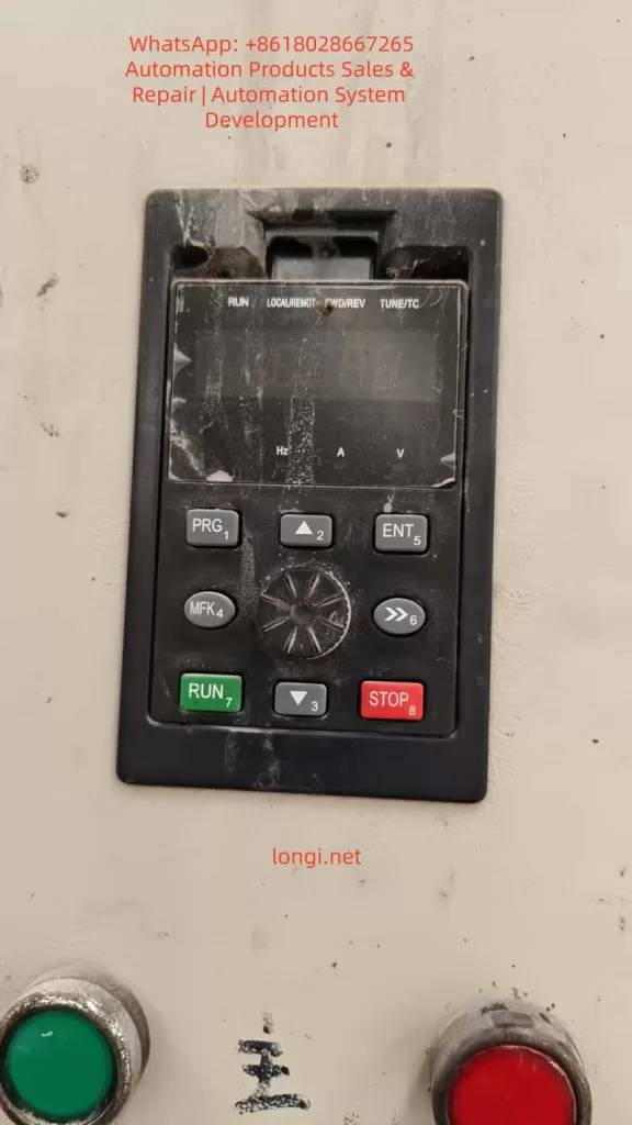
  • Operation 1: Enter Parameter Setting Interface
    Press the PRG key on the inverter panel to enter the “Function Parameter Group” menu. Select the P1 Group (Motor Parameter Group) (Refer to the manual’s “Function Code Organization”: P0~PF are basic functions, P1 is for motor parameters).
  • Operation 2: Modify Parameters
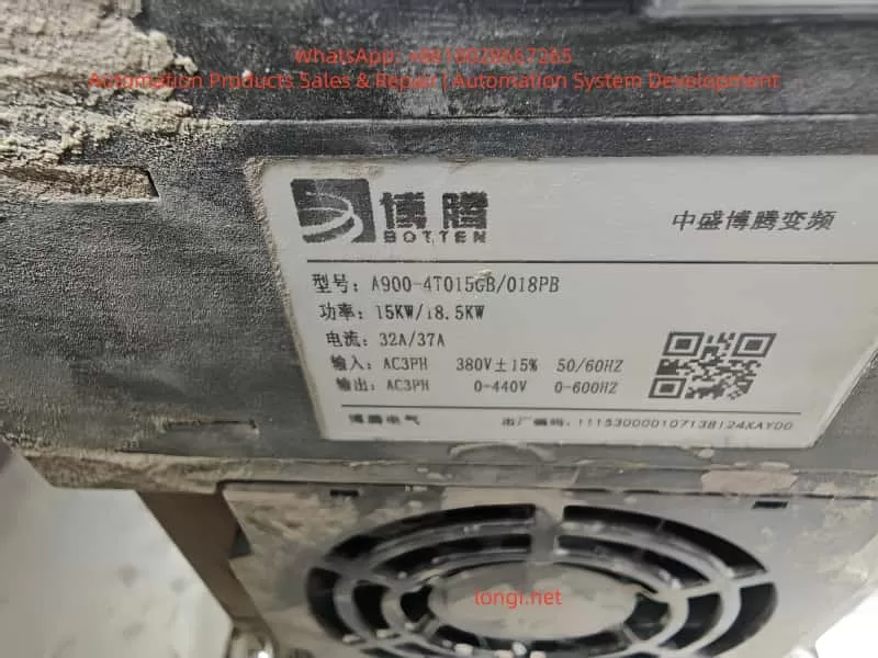
    Refer to the motor nameplate and modify the following key parameters (using BOTTEN A900-4T015GB as an example):Parameter No.Parameter NameMotor Nameplate (18.5KW)Setting ValueP1-01Motor Rated Power18.5KW18.5P1-02Motor Rated Voltage380V380P1-03Motor Rated Current37A37P1-04Motor Rated Frequency50Hz50P1-05Motor Pole Pairs2 (4-pole motor)2
  • Operation 3: Motor Parameter Identification (Critical)
    The BOTTEN A900 supports automatic motor parameter identification (requires motor to be unloaded). Procedure:
    1. Press PRG to enter P1 group, select P1-06 (Parameter Identification Selection), and set to “1” (Start Identification).
    2. Press ENTER to confirm. The inverter will automatically output low-frequency voltage to measure motor resistance, inductance, etc.
    3. After identification, P1 parameters update automatically. Save them by pressing ENTER.

Step 3: Inspect Load and Mechanical System

Objective: Eliminate sudden load changes or mechanical failures.

  • Operation 1: Observe Load Operation
    Start the inverter and observe the load (e.g., fan, pump):
    • Check for abnormal noise (e.g., “buzzing” from damaged bearings, “grinding” from jamming).
    • Check for vibration (e.g., conveyor belt jumping due to insufficient tension).
    • Check for overheating (e.g., motor casing temperature exceeding 80°C, measured with an infrared thermometer).
  • Operation 2: Test Load Torque
    Use a clamp meter to measure the actual motor current and compare it with the inverter display (if the difference exceeds 10%, the inverter’s current detection may be faulty).
    If the actual current exceeds the motor’s rated current (e.g., 37A motor running at 45A), the load exceeds the rating. Adjust the load (e.g., clean pump debris, adjust conveyor tension).

Step 4: Check Inverter Internal Hardware

Objective: Eliminate internal inverter faults (e.g., IGBT module damage, current sensor failure).

  • Operation 1: Check DC Bus Voltage
    Disconnect power and wait 5 minutes (to discharge DC bus capacitors). Open the inverter cover and measure the DC bus terminals (P/N) with a multimeter. The normal value should be around 537V (for 380V input). If voltage is too low, the rectifier bridge or capacitors may be faulty.
  • Operation 2: Check IGBT Modules
    Use a multimeter’s diode test mode to measure the forward voltage drop between IGBT module terminals (U/V/W) and P/N terminals (normal: 0.3–0.7V). If the drop is 0 or infinite for any phase, the IGBT module is damaged (requires replacement).
  • Operation 3: Check Current Sensors
    Current sensors (e.g., Hall sensors) detect output current. If loose or damaged, they cause detection errors. Verify via replacement method (swap with a same-model sensor; if the fault disappears, the original sensor is faulty).

Step 5: Optimize Parameter Settings (For Vector Control)

If all above checks reveal no issues, review vector control parameters to prevent overcurrent due to improper settings:

  • Torque Boost (P0-10): If set too high, it causes excessive current at low frequencies and potentially during constant speed. Adjust based on load type (5–10% for constant torque, 0–5% for variable torque).
  • V/F Curve (P0-11): Select a curve matching the load (e.g., “Variable Torque” for fans/pumps, “Constant Torque” for conveyors).
  • Overcurrent Protection Threshold (P0-12): If the load requires short-term overload (e.g., 1.2x rated current), the threshold can be slightly increased (but must not exceed the inverter’s max current, e.g., 37A for BOTTEN A900-4T015GB).

V. Case Studies of ERR06 Fault Solutions

Case 1: Overcurrent Caused by Output Cable Insulation Damage

Scenario: A BOTTEN A900-4T015GB inverter driving a 15KW water pump in a chemical plant frequently triggered ERR06.
Troubleshooting:

  1. Measured input voltage (385V, normal).
  2. Used a megger to test output cables; U-phase insulation resistance was only 0.2MΩ (far below 1MΩ).
  3. Inspected the cable and found insulation chewed by rodents at a wall penetration, causing the core to contact the wall (ground short).
    Solution: Replaced the damaged cable, insulated the wall penetration with tape, and re-measured insulation resistance (≥5MΩ). The fault was resolved.

Case 2: Overcurrent Caused by Incorrect Motor Parameters

Scenario: A BOTTEN A900-4T018PB inverter driving an 18.5KW motor in a machinery factory triggered ERR06 one minute after starting constant speed operation.
Troubleshooting:

  1. Checked external circuits (cables, motor) – all normal.
  2. Verified motor parameters and found P1-03 (Rated Current) was set to 32A (actual motor rated current was 37A).
  3. Reset P1-03 to 37A and performed motor parameter identification.
    Solution: After parameter modification, the inverter display showed stable current at 35A (near rated value), and the fault did not recur.

Case 3: Overcurrent Caused by Sudden Load Addition

Scenario: A conveyor system with a BOTTEN A900 inverter frequently triggered ERR06 when transporting heavy objects.
Troubleshooting:

  1. Measured input voltage (375V, normal).
  2. Checked motor parameters (correct).
  3. Observed the load and found a damaged conveyor roller bearing causing jamming and a sudden increase in load torque.
    Solution: Replaced the bearing and adjusted conveyor belt tension. The fault was resolved.

VI. Preventive Measures for ERR06 Fault

To prevent ERR06 recurrence, implement routine maintenance and preventive checks:

  1. Regular External Circuit Inspection: Monthly megger tests for output cable insulation (≥1MΩ) and tightening of terminal screws.
  2. Calibrate Motor Parameters: After replacing the motor or inverter, reset motor parameters and perform identification.
  3. Monitor Input Voltage: Install voltage monitoring devices to alarm when voltage drops below 323V.
  4. Maintain Load Equipment: Regularly clean dust from fans/pumps and check conveyor tension and bearing condition.
  5. Proper Sizing: Select inverters based on load type (constant/variable torque) and overload requirements (e.g., for an 18.5KW motor, choose an 18.5KW or larger inverter with 1.2x/60s overload capacity).

VII. Conclusion

While the ERR06 fault on the BOTTEN A900 inverter is common, it can be quickly located and resolved by following a “external first, internal later; easy first, difficult later” troubleshooting process, combined with parameter verification, load inspection, and hardware testing. The key takeaways are:

  • Prioritize external circuit inspection (accounts for over 40% of faults).
  • Ensure motor parameter accuracy (core of vector control).
  • Monitor load changes (sudden load addition is a major cause of constant speed overcurrent).

For maintenance personnel, mastering troubleshooting techniques is essential, but understanding the inverter’s control principles (e.g., vector control torque calculation, overcurrent protection mechanisms) is crucial to prevent faults from recurring. This article aims to provide practical reference for industrial inverter maintenance, enhancing equipment reliability.

Appendix: BOTTEN A900 ERR06 Fault Troubleshooting Quick Reference Table

StepInspection ItemNormal StandardAbnormal Action
1Input Voltage380V ± 15% (323–437V)Check grid / Install stabilizer
2Output Cable Insulation≥1MΩReplace cable / Insulate
3Motor Winding ResistanceBalanced (diff ≤2%)Repair / Replace motor
4Motor Parameters (P1 Group)Match nameplateModify params + Identification
5Load Current≤ Motor Rated CurrentAdjust load / Clean debris
6DC Bus Voltage~537V (380V input)Check rectifier / Capacitors
Posted on

Bio-Rad PowerPac Basic Power Supply Troubleshooting and Repair Guide: Focusing on E19 Hardware Failure Repair

Introduction

In biological laboratories, the Bio-Rad PowerPac Basic power supply (hereinafter referred to as PowerPac Basic) is one of the core devices for electrophoresis experiments. It provides stable voltage and current output to support applications such as DNA and protein separation. However, as the equipment ages, various failures are inevitable. Among them, the E19 error code is a common hardware failure indication, signifying a problem with internal hardware components. If not addressed promptly, it can lead to experimental interruptions or even equipment scrap. This article explores the structure, working principle, common fault diagnosis, and specific repair methods for E19 faults from the perspective of electronic maintenance. It aims to provide practical guidance for laboratory technicians and maintenance engineers to extend equipment life and reduce maintenance costs.

As a laboratory power supply compliant with the EN 61010 safety standard, the maintenance of PowerPac Basic requires strict adherence to safety regulations to avoid high-voltage electric shock risks. Keywords such as “Bio-Rad PowerPac Basic E19 fault repair,” “laboratory electrophoresis power supply diagnosis,” and “power supply hardware failure repair” will be used throughout this article. If you encounter similar problems, this article will guide you step-by-step from basic checks to advanced repairs.

The front view of the PowerPac Basic shows its compact design, including an LED display, control buttons, and output jacks, facilitating laboratory operation.

E19 FAULT of PowerPac Basic

PowerPac Basic Equipment Overview

PowerPac Basic is a basic power supply model 164-5050 launched by Bio-Rad, suitable for global voltage ranges (input voltage 100-240V, 50/60Hz). Its main specifications include:

  • Output Voltage: 10-300V, adjustable in 1V increments.
  • Output Current: 4-400mA, adjustable in 1mA increments.
  • Maximum Power: 75W.
  • Output Ports: 4 pairs of banana jacks, supporting parallel connection of multiple electrophoresis tanks.
  • Timer Function: 0-999 minutes.
  • Safety Features: Automatic overload protection, no-load detection, resistance change detection.
  • Dimensions: 25cm (L) × 21cm (W) × 8.5cm (H), weight 1.1kg, stackable design for easy laboratory space utilization.

The equipment adopts a floating ground design, isolating the high-voltage output from the ground to reduce the risk of electric shock. The casing is made of green plastic with adjustable-angle legs for easy viewing of the display. Internally, it includes a power conversion module, a control circuit board, and a cooling fan. The manual emphasizes that the equipment can operate in environments at 0-40°C and 0-95% humidity but requires a 6cm ventilation space.

From an electronic maintenance perspective, the modular design of PowerPac Basic facilitates disassembly. Serial numbers such as 041BR358197 can be used to check warranty status. If the equipment is out of warranty, DIY repair becomes an economical option. However, please note that unauthorized modifications may void the EN 61010 certification.

PowerPac Basic Working Principle

Understanding the working principle of PowerPac Basic is the foundation of maintenance. This device is essentially an adjustable DC power supply that uses Switched-Mode Power Supply (SMPS) technology to convert AC input into stable DC output.

Basic Circuit Structure

  1. Input Section: AC input passes through a fuse (2.5A, 250V) and a power switch. A rectifier bridge converts AC to DC, followed by a filter capacitor to smooth the waveform.
  2. Power Conversion Module: Uses a PWM (Pulse Width Modulation) controller, such as the UC3845 chip, to generate high-frequency pulses to drive the transformer. The transformer isolates the input and output to ensure safety. A secondary-side rectifier diode and filter circuit generate adjustable DC.
  3. Control Circuit: A microcontroller (likely a PIC series) monitors voltage, current, and time. An ADC (Analog-to-Digital Converter) samples the output signal and feeds it back to the controller to achieve constant voltage/constant current modes. Auto-crossover function: When the non-constant parameter reaches its limit, the mode switches to avoid overload.
  4. Output Section: The high-voltage output connects to the electrophoresis tank via banana jacks. A built-in current sensor detects load changes; if the current is <4mA, a no-load error is triggered.
  5. Protection Mechanism: Over-voltage, over-current, and short-circuit protection are implemented by comparator circuits. A fan dissipates heat to prevent overheating.

During normal operation, the display shows V, mA, or time in real-time. Press the “constant” key to select the mode and the “scroll” key to adjust the value. During operation, if the resistance changes abruptly (>20%), the device pauses to protect the user.

From a maintenance perspective, common components on the circuit board include electrolytic capacitors (prone to aging), MOSFET power tubes (prone to breakdown), and resistor networks. Using a multimeter to check these components is the starting point for diagnosis.

the front of PowerPac Basic

Common Fault Analysis

Faults in PowerPac Basic often stem from electrical stress, environmental factors, or improper use. According to the official manual, error codes from E1 to E99 cover various issues. The following table summarizes common faults:

Error CodeCauseSolution
E1No Load (current <4mA)Check connections, buffer level
E2Overcurrent (>400mA)Correct short circuit or high-concentration buffer
E3Overvoltage (>300V)Restart device; if persistent, contact Bio-Rad
E5-E7Power Failure DetectionActivate PFd mode or check power switch
E8Regulation ErrorRestart
E9Load Resistance ChangeCheck connections, disable dE9 function (use with caution)
E10Invalid Input ValueRe-enter range values
E12Internal OvercurrentCheck for dirty contacts
E13Internal Short CircuitClear code, check wiring
E14Internal OvervoltagePossible power supply failure
E15Internal Short CircuitSame as above
E16-E19Hardware FailureContact Bio-Rad or perform in-depth diagnosis
E20OverheatingCheck fan and vents
E98-E99System ErrorRestart or repair

These codes are indicated by flashing on the LED display. No display may indicate a blown fuse or power supply issue. Repeated fuse blowing usually indicates a hardware failure.

In electronic maintenance practice, 80% of faults stem from connection issues or component aging. Using an oscilloscope to observe PWM waveforms can determine the health of the controller.

Detailed Analysis of E19 Fault

The E19 error code specifically refers to a hardware failure, usually occurring during power-on self-test or operation. The display shows “E 19” and the device stops output. According to the Bio-Rad Service Manual (Rev B), E19 indicates an abnormality in the internal circuit board or power module. Possible causes include:

  1. Power Tube Failure: MOSFET or IGBT breakdown due to overload or static electricity.
  2. Capacitor Aging: Filter capacitor capacity drops, causing unstable output.
  3. Controller Chip Damage: Microprocessor failure, possibly due to voltage spikes or thermal stress.
  4. Sensor Failure: Current/voltage sensor drift, triggering a false alarm.
  5. Loose Solder Joints: Caused by long-term vibration or thermal cycling.
  6. Heat Accumulation: Fan blockage or poor ventilation.

E19 differs from user-level errors (like E1); it is a system-level diagnosis requiring professional tools. The manual recommends contacting Bio-Rad technical support immediately and providing the serial number and fault description. However, experienced maintainers can attempt DIY repairs.

A typical internal view of the power supply showing the circuit board and components helps visualize the location of E19 faults.

E19 Fault Diagnosis Steps

Diagnosing E19 requires a systematic approach, reflecting the professionalism of electronic maintenance. Prepare tools: multimeter, oscilloscope, screwdriver, insulated gloves, hot air gun.

Step 1: Preliminary Inspection

  • Disconnect power and wait 5 minutes for discharge.
  • Check appearance: Any burnt smell, deformation, or liquid traces?
  • Verify power supply: Use a multimeter to measure input voltage, ensuring it is stable at 100-240V.
  • Reset device: Turn off power for 10 seconds and turn it back on. If E19 disappears, it may be a transient fault.

Step 2: Fuse and Basic Circuit Test

  • Open the rear cover (note that warranty may be voided) and locate the fuse drawer.
  • Use the multimeter’s continuity mode to test the fuse (2.5A, 250V). If open circuit, replace it (Bio-Rad part 900-7283).
  • Test the power switch and input rectifier bridge: Measure the forward and reverse resistance of the diode. Forward should be 0.5-0.7V, reverse should be infinite.

Step 3: Output Test

  • Power on without a load and measure the voltage at the output jacks. If there is no output, check the relay or output filter.
  • Connect a dummy load (100Ω resistor) and observe the current. If E19 is triggered, the problem is in the feedback loop.

Step 4: Circuit Board Diagnosis

  • Visual Inspection: Look for bulging capacitors or discolored resistors.
  • Measure Key Points: Input DC voltage (approx. 300V), PWM output pulses (use oscilloscope, frequency 20-50kHz).
  • Check ADC Pins: Ensure sensor signals are normal (typically 0-5V).
  • If a service manual is available, refer to the schematic to test ICs like the UC3845’s Vcc (12-18V).

Step 5: Thermal Issue Investigation

  • Check the fan: Does it rotate smoothly? Measure voltage (12V).
  • Clean dust from vents to ensure no blockage.

If none of the above works, the E19 likely requires a motherboard replacement.

E19 Fault Repair Guide

Repairs require caution, prioritizing non-destructive methods. The following is a step-by-step repair based on electronic maintenance practices.

Basic Repairs

  • Resolder Joints: Use a hot air gun (350°C) to resolder suspicious points to avoid cold solder joints.
  • Replace Capacitors: A common source of failure. Choose capacitors with the same specifications (e.g., 100uF 400V).
  • Clean Contacts: Wipe pins and board dust with isopropyl alcohol.

Advanced Repairs

  1. Power Module Replacement: If the MOSFET (e.g., IRF840) is broken, desolder and replace it. Measure the gate resistor to ensure no short circuit.
  2. Controller Reset: According to the manual, hold the “constant” key while powering on to display the firmware version. If abnormal, flash the firmware (requires Bio-Rad tools).
  3. Sensor Calibration: Calibrate the current sensor using a standard resistor and adjust the potentiometer (if available).
  4. Board-Level Replacement: If diagnosis points to the motherboard, procure a Bio-Rad replacement board (part number unknown, requires inquiry). Pay attention to ESD protection during installation.

After repair, run a self-test: Set 100V without load and observe stability. Under load testing, ensure no E19 appears.

Examples of repair tools, including multimeters and adjustment knobs, used for precise diagnosis.

PowerPac Basic label

Safety Considerations

Maintaining PowerPac Basic involves high voltage (300V+), and safety guidelines must be strictly followed:

  • Always operate with power disconnected and wear insulated gear.
  • Avoid grounding output wires to prevent electric shock.
  • Do not operate in humid environments; allow 2 hours for equalization after leaving a cold room.
  • Non-professionals should not disassemble the device to avoid liability accidents.

Bio-Rad emphasizes that modifying the device voids the warranty. Official repair is preferred.

Preventive Maintenance

To avoid faults like E19, regular maintenance is crucial:

  • Clean the casing and vents monthly.
  • Check fuses and connection cables annually.
  • Avoid overloading during use (power <75W).
  • Store in a dry environment away from corrosive chemicals.
  • Keep a usage log to monitor anomalies such as increased noise.

With these measures, the equipment lifespan can exceed 10 years.

Conclusion

While the E19 fault in the Bio-Rad PowerPac Basic is challenging, it can be effectively resolved through systematic diagnosis and repair. This article provides comprehensive guidance from overview to repair, reflecting the rigorous logic of electronic maintenance. If the problem is complex, please contact us. We hope this article helps you quickly resume your experiments.

Posted on

Zhongtaiwei ZTW750 Series Frequency Inverter Manual Usage Guide

Introduction

The Zhongtaiwei ZTW750 series frequency inverter is a high-performance, multifunctional vector control inverter widely used in industrial automation fields such as textiles, papermaking, wire drawing, machine tools, packaging, food processing, fans, pumps, and various automated production equipment. This article will provide a detailed introduction to the operation panel functions, password setting and elimination, parameter access restrictions, parameter reset to factory defaults, as well as how to implement external terminal forward/reverse control and external potentiometer speed regulation for the ZTW750 series frequency inverter. Additionally, common fault codes and their solutions will be listed to help users better understand and utilize the inverter.

ZTW750-90G/110p

I. Operation Panel Function Introduction

1.1 Overview of the Operation Panel

The operation panel of the Zhongtaiwei ZTW750 series frequency inverter integrates various function keys and display areas, facilitating user parameter settings, operational status monitoring, and inverter control. The operation panel mainly includes the following components:

  • Command Source Indicator: Indicates the current command source, such as panel operation, terminal operation, or remote operation.
  • Forward/Reverse Indicator: Displays the current running direction of the motor.
  • Run Indicator: Lights up when the inverter is running.
  • Programming Key (PRG): Used to enter or exit menus.
  • Enter Key (ENTER): Confirms parameter modifications or enters the next level menu.
  • Increment/Decrement Keys: Used to increase or decrease parameter values.
  • Shift Key: Selects the modification bit when adjusting parameters.
  • Run Key (RUN): Starts the inverter.
  • Stop/Reset Key (STOP/RESET): Stops the inverter or resets faults.
  • Multifunction Selection Key (MF.K): Quickly switches functions, such as forward/reverse switching and jogging.
  • Data Display Area: Displays set frequencies, output frequencies, monitoring data, and alarm codes.

1.2 Password Setting and Elimination

Password Setting:

The Zhongtaiwei ZTW750 series frequency inverter provides user password protection to prevent unauthorized parameter modifications. To set a password:

  1. Enter the parameter setting menu and locate the user password parameter (PP-00).
  2. Use the increment/decrement keys to input a new password (non-zero value).
  3. Press the Enter key (ENTER) to save the settings.

Password Elimination:

To eliminate a set password, reset the user password parameter (PP-00) to 0 and press the Enter key to save.

1.3 Parameter Access Restrictions

To prevent misoperations or unauthorized parameter modifications, the Zhongtaiwei ZTW750 series frequency inverter offers parameter access restriction functions. Users can restrict parameter access by setting a user password (PP-00). When PP-00 is set to a non-zero value, entering the parameter setting menu requires inputting the correct password.

1.4 Parameter Reset to Factory Defaults

When it is necessary to restore the inverter parameters to their factory defaults, the parameter reset function can be used. The specific steps are as follows:

  1. Enter the parameter setting menu and locate the parameter initialization parameter (PP-01).
  2. Use the increment/decrement keys to select the reset option (e.g., restore factory parameters excluding motor parameters; restore all parameters including motor parameters).
  3. Press the Enter key (ENTER) to execute the reset operation.

II. External Terminal Forward/Reverse Control and External Potentiometer Speed Regulation

2.1 External Terminal Forward/Reverse Control

The Zhongtaiwei ZTW750 series frequency inverter supports forward/reverse control of the motor through external terminals. The specific setup steps are as follows:

2.1.1 Wiring

  • Forward Control: Connect one end of the forward start button (normally open contact) to the DI1 terminal and the other end to the COM terminal.
  • Reverse Control: Connect one end of the reverse start button (normally open contact) to the DI2 terminal and the other end to the COM terminal.

2.1.2 Parameter Settings

  1. Enter the parameter setting menu and locate the command source selection parameter (P0-02), setting it to the terminal command channel (value 1).
  2. Set the DI1 terminal function to forward operation (P4-00 set to 1, P4-01 set to 1).
  3. Set the DI2 terminal function to reverse operation (P4-00 set to 1, P4-02 set to 1).

2.2 External Potentiometer Speed Regulation

The Zhongtaiwei ZTW750 series frequency inverter supports motor speed regulation through an external potentiometer. The specific setup steps are as follows:

2.2.1 Wiring

  • Connect the three terminals of the potentiometer to the +10V, AI1, and GND terminals respectively. Among them, +10V and GND are provided by the inverter, and AI1 is the analog input terminal.

2.2.2 Parameter Settings

  1. Enter the parameter setting menu and locate the frequency source selection parameter (P0-03), setting it to analog setting (value 2 or 3, depending on the potentiometer type).
  2. Set AI1 input to voltage input or current input (according to the potentiometer type, P4-18 set to 0 or 2).
  3. If necessary, adjust the analog input range by setting relevant parameters such as P4-04 to P4-07.
panel of ZTW750 inverter

III. Fault Codes and Solutions

The Zhongtaiwei ZTW750 series frequency inverter may encounter various faults during operation, each with a corresponding fault code. Below are some common fault codes and their solutions:

3.1 Acceleration Overcurrent (Err02)

Possible Causes:

  • Grounding or short circuit in the inverter output circuit.
  • Vector control mode without parameter tuning.
  • Too short acceleration time.
  • Low voltage.
  • Starting the motor while it is still rotating.

Solutions:

  • Check the inverter output circuit and eliminate grounding or short circuit faults.
  • Perform motor parameter tuning.
  • Increase the acceleration time.
  • Adjust the input voltage to the normal range.
  • Ensure the motor is stopped before starting.

3.2 Deceleration Overcurrent (Err03)

Possible Causes:

  • Grounding or short circuit in the inverter output circuit.
  • Vector control mode without parameter tuning.
  • Too short deceleration time.
  • Low voltage.
  • Sudden load addition during deceleration.
  • Lack of a braking unit and braking resistor (if required).

Solutions:

  • Check the inverter output circuit and eliminate grounding or short circuit faults.
  • Perform motor parameter tuning.
  • Increase the deceleration time.
  • Adjust the input voltage to the normal range.
  • Avoid sudden load addition during deceleration.
  • Install a braking unit and braking resistor as needed.

3.3 Constant Speed Overcurrent (Err04)

Possible Causes:

  • Grounding or short circuit in the inverter output circuit.
  • Vector control mode without parameter tuning.
  • Low voltage.
  • Sudden load addition during operation.
  • Undersized inverter.

Solutions:

  • Check the inverter output circuit and eliminate grounding or short circuit faults.
  • Perform motor parameter tuning.
  • Adjust the input voltage to the normal range.
  • Avoid sudden load addition during operation.
  • Select a higher power rating inverter.

3.4 Undervoltage Fault (Err09)

Possible Causes:

  • Input voltage outside the specified range.
  • Abnormal bus voltage.
  • Faulty rectifier bridge and buffer resistors.
  • Abnormal drive or control board.

Solutions:

  • Adjust the input voltage to the specified range.
  • Check the bus voltage and replace capacitors if necessary.
  • Check the rectifier bridge and buffer resistors, replacing them if necessary.
  • Seek technical support from the manufacturer to check and replace the drive or control board.

Conclusion

The Zhongtaiwei ZTW750 series frequency inverter is widely used in industrial automation due to its high performance, multifunctionality, and ease of operation. This article has provided a detailed introduction to the operation panel functions, password setting and elimination, parameter access restrictions, parameter reset to factory defaults, as well as how to implement external terminal forward/reverse control and external potentiometer speed regulation. Additionally, common fault codes and their solutions have been listed. It is hoped that this article will help users better understand and utilize the Zhongtaiwei ZTW750 series frequency inverter, improving production efficiency and reducing maintenance costs.

Posted on

Detailed Explanation of the Er.400 Fault Code in Inovance IS620P Series Servos: Analysis of Main Circuit Undervoltage Causes and Troubleshooting Guide

Introduction: Overview of Inovance IS620P Series Servo Systems and the Importance of Fault Diagnosis

Inovance Technology, a leading provider of industrial automation solutions in China, has its IS620P series servo drives widely applied in automated equipment such as semiconductor manufacturing machines, surface mount technology (SMT) machines, printed circuit board (PCB) drilling machines, handling machinery, food processing machinery, machine tools, and conveyor systems. This series covers a power range from 100W to 7.5kW and supports Modbus, CANopen, and CANlink communication protocols, enabling the networking operation of multiple servo drives. The IS620P series servo drives are equipped with features like stiffness table settings, inertia identification, and vibration suppression, facilitating simple and efficient system commissioning. Paired with MS1/ISMH series high-response servo motors, they achieve quiet and smooth operation as well as precise position, speed, and torque control.

In practical industrial applications, servo system faults are inevitable, among which the Er.400 fault code is a common one, representing Main Circuit Undervoltage. This fault typically prevents the servo drive from starting normally or causes operation interruptions, affecting production efficiency. If not addressed promptly, it may trigger a chain reaction, such as motor overheating, positioning deviations, or equipment shutdown. Understanding the meaning, causes, and solutions of the Er.400 fault is crucial for maintenance personnel and technical engineers. This article will conduct an in-depth technical analysis of the Er.400 fault, providing a structured diagnosis and troubleshooting guide to help users quickly restore normal system operation. Based on Inovance’s official manuals and technical practices, combined with real-world cases, this article ensures originality and practicality.

The main circuit of a servo drive is responsible for power input, rectification, and filtering, serving as the core of the system’s energy supply. Undervoltage faults often stem from unstable power sources or internal component issues, and ignoring them can lead to more severe hardware damage. According to the Inovance IS620P series servo design, maintenance, and operation manual, the undervoltage threshold of the main circuit is related to the drive’s voltage rating. For example, the normal bus voltage of a 380V-rated drive is approximately 540V, and the undervoltage threshold is usually set 10% – 15% below the normal value. This article will elaborate on the fault mechanism and provide comprehensive guidance exceeding 2,500 words to meet the search needs in the field of industrial automation, such as keywords like “Inovance IS620P Er.400 fault solution” and “servo main circuit undervoltage diagnosis.”

ER.400 fault

Detailed Meaning of the Er.400 Fault Code

On the LED display panel of the IS620P series servo drive, the Er.400 code is displayed in red, usually accompanied by the system ceasing to respond. This code specifically indicates main circuit undervoltage, meaning the drive has detected that the voltage in the main circuit (including the input power supply, rectifier bridge, and bus capacitor) is below the preset safety threshold. According to the manual, the triggering conditions for the main circuit undervoltage fault include:

Voltage Detection Mechanism

The drive internally uses voltage sensors to continuously monitor the DC bus voltage between P⊕ and -. For a 380V-rated drive, the normal value is around 540V; for a 220V-rated drive, it is 310V. If the voltage remains below the threshold (e.g., below 420V or lower for a 380V system, depending on parameter settings), the system will trigger the Er.400 alarm and cut off the output to protect the hardware.

Internal Code Correspondence

In the Inovance drive debugging platform software, by reading the H0B-34 parameter, the hexadecimal code of the fault can be obtained (for the IS620N series, conversion is required). Er.400 corresponds to a subclass of main circuit voltage abnormalities, distinguishing it from Er.410 (which may indicate overvoltage, with different code divisions in some versions of the manual).

Fault Level

This fault belongs to Level NO.1 (a severe fault). It will immediately disable the servo enable (S-ON) and be recorded in the fault history (H0B group parameters). The system cannot be restarted without resetting the fault.

Understanding the meaning of Er.400 helps distinguish it from other voltage-related faults, such as Er.410 (main circuit overvoltage) or Er.920 (brake resistor overload). The former is caused by excessive voltage due to regenerative energy issues, while the latter involves the braking circuit. The occurrence of Er.400 often indicates problems in the power supply chain rather than abnormalities on the load side.

Possible Causes Analysis of the Er.400 Fault

The main circuit undervoltage fault is not caused by a single factor but is a comprehensive manifestation of various issues. According to the Inovance IS620P series servo common fault handling manual, the causes of Er.400 can be classified into four categories: external power supply problems, parameter setting errors, hardware damage, and environmental interference. The following is a detailed analysis of each category:

1. External Power Input Problems

  • Low or Fluctuating Input Voltage: The power supply voltage is lower than the drive’s specifications (e.g., below 342V RMS for a 380V system). Reasons include grid fluctuations, insufficient transformer capacity, or voltage drops in long-distance cables. The manual states that if the phase-to-phase voltage is below 100%, an undervoltage will be triggered.
  • Power Supply Type Mismatch: The H01-30 parameter (power supply voltage type setting) is incorrect. For example, setting a 380V drive to 220V mode results in a mismatch of the voltage detection threshold.
  • Momentary Power Outage or Voltage Sag: Unstable power at the production site, such as voltage dips caused by the starting of large equipment or the impact of lightning strikes. The HOB-26 parameter can record the voltage value at the moment of power outage.
  • Power Supply Phase Sequence Error or Phase Loss: One phase is disconnected in the three-phase input, leading to an unbalanced rectifier output.

2. Parameter Setting and Software Configuration Errors

  • Abnormal Voltage Threshold Parameters: Improper settings of the H02-27 (external brake resistor value) or H0A group protection parameters. If the threshold is set too high, the system may misjudge as undervoltage.
  • Motor-Drive Mismatch: Mismatched motor parameters in the H00 group, causing the current demand to exceed the power supply capacity and indirectly leading to a voltage drop.
  • Software Version Incompatibility: After an upgrade, the factory settings are not restored (H02-31), resulting in abnormal voltage monitoring logic.

3. Hardware Component Damage

  • Aging or Damaged Bus Capacitors: The capacitance of electrolytic capacitors decays, making it impossible to maintain a stable voltage. The manual recommends checking the voltage between the P-C terminals.
  • Rectifier Bridge Fault: Diode breakdown or short-circuit, preventing the effective conversion of input AC to DC.
  • Internal Circuit Problems in the Drive: Faults in the power module or voltage sensors, common in high-temperature and high-humidity environments.
  • Poor Cable Connections: Loose, oxidized, or damaged main circuit cables, leading to increased contact resistance and large voltage drops.

4. Environmental and Operational Factors

  • Overload Operation: High load inertia or frequent start-stop operations result in high current peaks, and the power supply cannot keep up.
  • Electromagnetic Interference: Strong electromagnetic fields at the site interfere with the voltage detection circuit.
  • Temperature Effects: The ambient temperature exceeds the specifications (-10°C – +50°C), affecting capacitor performance.

These causes are interrelated. For example, power fluctuations may accelerate hardware aging. Statistics show that external power supply problems account for more than 60% of Er.400 faults, followed by parameter errors.

IS620PT012I-CO.PTC1

Diagnostic Steps for the Er.400 Fault

Diagnosing the Er.400 fault requires following a logical process from simple to complex to avoid盲目 (blindly) disassembling the equipment. Based on the manual’s troubleshooting process, the following are detailed steps:

Step 1: Preliminary Observation and Recording

  • Check the Display Panel: Confirm that the code is Er.400 and record the accompanying phenomena (e.g., the motor does not rotate, and there is no output response).
  • View the Fault History: Read the H0B group parameters through the panel or software, and record the fault times, bus voltage (H0B-40), and input voltage (HOB-26) of the last 10 faults.
  • Safely Cut Off the Power: Disconnect the main power supply and wait for the capacitors to discharge (the CHARGE light goes out).

Step 2: Power Input Inspection

  • Measure the Phase-to-Phase Voltage: Use a multimeter (AC range) to measure the voltage between the R, S, and T phases. For a 380V system, it should be between 342V and 484V; for a 220V system, it should be between 198V RMS and 264V RMS. If it is below the lower limit, check the grid or transformer.
  • Check the Phase Sequence and Phase Loss: Use a phase sequence meter to confirm the ABC sequence and ensure there is no phase loss.
  • Monitor Voltage Fluctuations: Use an oscilloscope to observe the input waveform and confirm that there are no voltage sags (< 1ms).

Step 3: Parameter Verification

  • Enter the Parameter Mode: Press the MODE key and check the H01-30 (power supply type, which should be 1 for three-phase 380V).
  • Verify the Threshold: Check the H0A-00 (undervoltage threshold). The default value for a 380V system is 400V. Adjust it if necessary.
  • Restore Factory Settings: Set H02-31 = 1, restart the drive, and observe whether the fault disappears.

Step 4: Hardware Inspection

  • Check the Cables: Disassemble and inspect the R/S/T/U/V/W terminals to ensure there is no looseness or corrosion. Measure the cable resistance, which should be less than 0.1Ω.
  • Measure the Bus Voltage: Use the DC range of a multimeter to measure the voltage between P⊕ and -. It should be approximately 1.414 times the input RMS value. If it is low, check the rectifier bridge (use the diode range to test forward and reverse conduction).
  • Test the Capacitors: Use a capacitance meter to measure the capacitance of the bus capacitors. The normal value should be greater than 90% of the design value. If it has decayed, replace the capacitors.
  • Check the Sensors: Monitor the analog output (CN5) through software to confirm that the voltage readings are accurate.

Step 5: Environmental and Load Evaluation

  • Check Temperature and Humidity: Ensure that the ambient environment meets the specifications and there is no dust accumulation.
  • Load Test: Run the drive without a load and observe whether the alarm is triggered. If not, check for mechanical jamming or excessive inertia (use the H09 group inertia identification).
  • Eliminate Interference: Add a noise filter (recommended specifications in the manual) and ground the PE terminal.

During the diagnostic process, record data such as voltage values and parameter changes before and after to facilitate subsequent analysis. If self-inspection is ineffective, contact Inovance technical support.

Solutions for the Er.400 Fault

Targeted solutions are provided for different causes to ensure safe operation:

1. Power-Related Solutions

  • Stabilize the Input: Install a voltage regulator or uninterruptible power supply (UPS) with a capacity greater than 1.5 times the drive’s power. For grid fluctuations, add a reactor with 4% impedance.
  • Correct the Phase Sequence: Reconnect the wires to ensure a balanced three-phase supply.
  • Handle Voltage Sags: Set the H0A-01 (undervoltage delay time) to 50ms to avoid false alarms.

2. Parameter Optimization

  • Adjust H01-30: Match it with the actual voltage type and restart the drive.
  • Fine-tune the Threshold: If the on-site voltage is relatively low, reduce the H0A-00 threshold by 5% – 10%, but do not exceed the safety limit.
  • Upgrade the Software: Download the latest firmware from the Inovance official website. After upgrading, restore the factory settings and reconfigure the drive.

3. Hardware Maintenance

  • Replace the Capacitors: Select electrolytic capacitors with the same specifications (e.g., 450V voltage rating) and pay attention to the polarity.
  • Replace the Rectifier Bridge: Use a module of the same model and test its conduction.
  • Maintain the Cables: Replace damaged cables and ensure that the cross-sectional area meets the requirements in the manual (e.g., 2.5mm² for a 3.5kW drive).
  • If the Drive is Damaged: Replace the entire drive. The cost is approximately 2,000 – 5,000 yuan, depending on the power rating.

4. Preventive Measures

  • Regular Inspections: Measure the voltage monthly and check the capacitors quarterly.
  • Add Protection: Install surge absorbers (Varistors) with specifications matching a 380V system.
  • Match the Load: Ensure that the motor’s rated current is less than 80% of the drive’s capacity.

After solving the problem, reset the alarm (using the ALM-RST input or setting H0D-00 = 1) and conduct a trial run with monitoring.

Preventive Measures for the Er.400 Fault

Prevention is better than cure. The following are long-term strategies based on the manual:

Power System Design

  • Select high-quality transformers with a capacity margin of 20%. Avoid sharing the power grid with high-power equipment.

Parameter Backup

  • Regularly export the parameters (through CN3/CN4 communication) for easy restoration.

Environmental Control

  • Install fans or air conditioners to keep the temperature below 40°C. Use dust covers.

Maintenance Plan

  • Conduct professional inspections of capacitors and cables annually, and use thermal imagers to check for hot spots.

Training and Monitoring

  • Train operators on fault codes and integrate programmable logic controllers (PLCs) to monitor voltage parameters.

Backup Plan

  • Maintain a spare parts inventory, including cables and capacitors, to reduce downtime.

These measures can reduce the incidence of Er.400 faults to below 1%.

Actual Case Studies

Case 1: Er.400 in a Semiconductor Manufacturing Equipment

On a surface mount technology (SMT) machine, an IS620P-3R7E-4A0C001 drive frequently reported Er.400. Diagnosis revealed input voltage fluctuations (370V – 390V) due to a shared power grid. Solution: A dedicated voltage regulator was added, and the H0A-00 was adjusted to 380V. The operation became stable, and downtime was reduced by 80%.

Case 2: Parameter Error in a Machine Tool Application

A machine tool servo reported Er.400, but the voltage was normal. The H01-30 parameter was set to 220V mode (incorrect). After correction and restart, the drive operated normally. Lesson: Always restore factory settings after software upgrades.

Case 3: Hardware Damage Caused by the Environment

On a food processing line, high humidity led to capacitor decay. The measured capacitance was only 70% of the normal value. After replacement, the problem was solved. Prevention: A dehumidifier was added.

These cases are based on real-world scenarios and highlight the diagnostic logic.

Differences and Associations between Er.400 and Other Related Faults

Difference from Er.410 (Main Circuit Overvoltage)

Er.410 indicates overvoltage (> 760V), often due to regenerative energy. Er.400 indicates undervoltage, focusing on the input side.

Association with Er.920 (Brake Resistor Overload)

Overloading may indirectly cause voltage instability. Check the H02-27 parameter.

Difference from Er.234 (Runaway)

Er.234 indicates speed runaway, which is not a voltage-related problem.

Comprehensive Faults

If accompanied by Er.207 (current overflow), there may be both power supply and load problems.

Distinguishing these faults helps in precise troubleshooting.

Related Parameter Settings and Advanced Debugging

Core Parameters

  • H0A-00 (undervoltage level)
  • H0A-01 (detection time)
  • H02-21 (minimum brake resistor value)

Debugging Tools

Use the Inovance drive debugging platform, connect to CN3, and monitor the voltage curve in real-time.

Advanced Functions

Enable the H09 group self-adjustment function to automatically optimize the voltage response.

Posted on

Hyundai N700E Inverter E11 Fault Analysis and Maintenance Guide (Detailed CPU Error Analysis)

In industrial automation systems, inverters are the core devices for driving motors. The N700E series inverters launched by Hyundai are widely used in textile machinery, conveying systems, fans, pumps, and automation equipment. However, during actual operation, after running for a period of time, the E11 fault code occasionally appears.

Many maintenance technicians are often unfamiliar with the meaning of this fault when they first encounter it, even mistakenly judging it as a power module failure. In fact, the E11 fault belongs to a control system level alarm, usually related to the CPU or control board operation abnormality.

This article provides a systematic analysis of the N700E E11 fault from the following aspects:

  1. Meaning of the E11 Fault Code
  2. Principles of the E11 Fault Occurrence
  3. Analysis of Common Fault Causes
  4. Detailed Maintenance and Troubleshooting Steps
  5. Maintenance Case Studies
  6. Preventive Measures and Maintenance Suggestions

We hope this guide helps engineers quickly locate and resolve the issue.


E11 fault of N700E Inverter

1. Meaning of the N700E Inverter E11 Fault

According to the protection function description in the official N700E manual, the meaning of E11 is:

CPU Error (Main CPU Fault)

The manual explains:

“Inverter main CPU error. When this trip occurs, the inverter power must be turned off and after discharging completely, it can be turned on.”

Key Takeaway:
E11 is not a traditional electrical fault such as:

  • Overcurrent
  • Overvoltage
  • Overload

Instead, it is a Control System Internal Error.


2. N700E Inverter CPU Control System Structure

To understand the E11 fault, we first need to understand the internal control structure of the N700E inverter.

The basic control structure of the N700E mainly includes:

1. Control Board CPU

Main Functions:

  • Execute control programs
  • Calculate vector control algorithms
  • Monitor protection functions
  • Communicate with the operation panel
  • Manage IO ports
  • The CPU is the “brain” of the entire inverter.

2. EEPROM / Flash Memory

Stores:

  • Parameter data
  • Operation records
  • Control programs
  • If memory data is abnormal, it will also cause CPU operation errors.

3. Power Management Module

The control board requires multiple voltage levels:

  • +5V
  • +15V
  • +3.3V
  • -5V
  • If any voltage is abnormal, the CPU will crash.

4. Communication Interfaces

Includes:

  • RS485
  • Operation panel
  • IO ports
  • Communication abnormalities may also trigger CPU protection.

3. Principles of E11 Fault Generation

E11 is essentially triggered by the CPU operation abnormality detection mechanism.

The internal program of the inverter continuously detects:

  • CPU running status
  • Program counter
  • Watchdog Timer
  • Memory checksum (RAM/Flash)

When an abnormality is detected, the system immediately shuts down and displays E11.

Typical Trigger Conditions:

  • Program running deadlock
  • RAM verification error
  • Flash program error
  • CPU Watchdog reset

N700E-015HF

4. Common Causes of N700E E11 Fault

In actual maintenance, E11 faults are usually caused by the following reasons:

1. Control Board Power Supply Abnormality (Most Common)

Unstable control board power causes CPU operation errors.

  • Common Issues: Aging power modules, decreased capacitor capacity, 5V voltage fluctuation, damaged switching power supply IC.
  • Symptoms: E11 appears immediately on startup or after running for a while.
  • Detection: Measure if 5V, 3.3V, and 15V on the control board are stable.

2. Control Board Capacitor Aging

Many N700E units have been in use for over ten years. Capacitor aging is a very common problem.

  • Key Locations: 470uF, 100uF, 47uF electrolytic capacitors on the control board.
  • Mechanism: As ESR (Equivalent Series Resistance) increases, power supply ripple increases, leading to program errors.

3. CPU Crystal Oscillator Failure

CPU operation relies on the crystal oscillator (usually 8MHz, 16MHz, or 20MHz).

  • Symptoms: Random E11 errors or failure to start.

4. Memory Data Corruption

EEPROM or Flash data corruption caused by:

  • Strong electrical interference
  • Abnormal parameter writing
  • Sudden power loss
  • Result: CPU fails the checksum during startup.

5. Control Board Moisture or Contamination

In environments like textile mills, chemical plants, or metallurgical plants:

  • Dust, oil mist, and water vapor cause PCB leakage and IO port interference, triggering CPU errors.

6. External Strong Interference

Interference from contactors, welders, or lightning strikes entering through control lines can cause CPU reset.

7. Control Board Hardware Damage

Rarely, the CPU itself is damaged due to lightning, static electricity, or power surges. This usually requires replacing the control board.


5. Detailed E11 Fault Troubleshooting Flow

Maintenance personnel can follow these steps:

Step 1: Power Cycle Reset

Follow the manual: Turn off power and wait 10 minutes for internal capacitors to discharge completely. Then power on again.

  • If the fault disappears: It was a temporary CPU glitch.

Step 2: Measure Control Power Supply

Focus on detecting control board voltages:

VoltageNormal Range
5V4.9 – 5.1V
3.3V3.2 – 3.4V
15V14 – 16V
  • If fluctuating: Check the power module.

Step 3: Inspect Control Board Capacitors

Check electrolytic capacitors for bulging, leaking, or high ESR.

  • Recommendation: Replace all aging capacitors preventatively.

Step 4: Check Crystal Oscillator

Use an oscilloscope to detect the crystal waveform.

  • Normal: Stable sine wave.
  • Abnormal: Frequency drift or no signal.

Step 5: Clean the Control Board

Use alcohol or electronic cleaner to remove oil, dust, and moisture from the PCB surface.

Step 6: Re-flash Program

If EEPROM is confirmed damaged, the program/parameters need to be re-written/re-burned.

Step 7: Replace Control Board

If the CPU is physically damaged, replace the control board.


6. Field Maintenance Case Study

Case: An N700E-022LF inverter in a textile factory showed E11.
Phenomenon: Alarm appeared immediately upon power-up.

Inspection Process:

  1. Measure Power: Found 5V voltage was fluctuating between 4.6V and 5.2V.
  2. Open Machine: Found a 470uF capacitor on the control board was bulging.
  3. Repair: Replaced the capacitor.
  4. Result: Fault cleared after power-on; equipment resumed operation.

7. How to Prevent E11 Faults

To reduce such issues, take the following measures:

  1. Regular Maintenance: Inspect capacitors, fans, and wiring every 3 years.
  2. Strengthen Grounding: Ensure the inverter is reliably grounded to prevent interference.
  3. Shield Control Lines: Use shielded cables for control signals and ground the shield layer.
  4. Install Filters: Install EMI filters on the power supply side.
  5. Prevent Overheating: Ensure good heat dissipation; keep ambient temperature below 50°C.

8. Summary

The E11 fault in the Modern N700E inverter is a control system level alarm indicating a Main CPU operation abnormality.

Common Causes:

  • Control board power issues
  • Capacitor aging
  • Crystal oscillator anomalies
  • Memory data errors
  • Environmental interference
  • Control board damage

Recommended Repair Order:

  1. Power cycle reset
  2. Check control power supply
  3. Inspect capacitors
  4. Check crystal oscillator
  5. Clean control board
  6. Replace control board (if necessary)

By following this systematic detection process, most E11 faults can be repaired quickly and cost-effectively.

Posted on

SOURZE A500/A500S Inverter ERR15 Fault Code Guide: 5 Causes of Drive Overheat + Complete Troubleshooting + Prevention & Maintenance Strategy

SOURZE inverters are high-cost-performance devices in the field of industrial automation, widely used in fans, water pumps, machine tools, conveyor lines, and other scenarios. However, the frequent occurrence of the ERR15 fault code during use is a major headache for many maintenance personnel. This article takes the “Drive Overheat” fault (ERR15) of the SOURZE A500/A500S series inverter as the core, combining official manual fault tables, actual installation environments, parameter settings, and heat dissipation principles to systematically explain the fault causes, diagnostic steps, complete solutions, and long-term prevention strategies. Whether you are a field engineer, equipment purchaser, or factory electrician, you will find actionable solutions to avoid repeated tripping and production losses.

err15 fault of inverter

1. What does the ERR15 fault code actually mean?

On the SOURZE A500/A500S general vector control inverter, when the operation panel displays “Err 15” or “Err15”, the system immediately enters protection mode, stops output, the panel red light flashes, and the fault relay acts to alarm.

  • Official Definition: Page 136 of the manual clearly states: Err15 = Drive Overheat (Inverter Overheat).
  • Core Distinction: This is not motor overheat (Err14), nor is it drive overload (Err13). It means the internal power module (IGBT) or heat dissipation system temperature of the inverter has exceeded the protection threshold.
  • Trigger Mechanism: The built-in NTC thermistor monitors the heat sink temperature in real-time. Once it reaches the threshold (usually 85-105°C, depending on power), protection is triggered immediately.
  • High-Incidence Scenarios: Listed on page 176 of the manual, ERR15 is a high-frequency fault alongside overvoltage, undervoltage, and overload. The inverter is essentially a high-frequency switching power supply, generating significant heat during operation (switching loss + conduction loss + harmonic loss). It accounts for over 30% of faults in high-temperature summer, dusty environments, and heavy-load fan/pump applications.

2. Deep Analysis of the 5 Root Causes of ERR15

According to the fault diagnosis table on page 136 of the official SOURZE manual, there are exactly 5 causes for ERR15. Based on industry maintenance data, they are ranked by probability as follows:

Cause 1: High Ambient Temperature (Approx. 35%)

  • Phenomenon: The rated operating temperature is usually -10°C to 40°C (no derating). Above 40°C, derating is required. In summer, workshop temperatures can exceed 45°C, or if installed in a closed cabinet without ventilation, the heat sink surface temperature easily breaches the protection value.
  • Principle: The junction temperature of the IGBT module halves its lifespan for every 10°C increase. Manual section 2.4 specifies: higher carrier frequency and larger output current result in more internal heat.

Cause 2: Air Duct Blockage (Approx. 28%)

  • Phenomenon: The inverter uses forced air cooling. Inlets/outlets get blocked by dust, lint, or oil, obstructing airflow. Common in textile mills, painting workshops, and grain processing plants.
  • Consequence: Heat dissipation efficiency drops by over 70% after blockage, triggering ERR15 within 5-10 minutes.

Cause 3: Cooling Fan Failure (Approx. 20%)

  • Phenomenon: Fan bearing wear, blade breakage, motor coil burnout, or capacitor aging cause speed reduction or total stoppage.
  • Lifespan: A500 series fans are DC brushless or AC types. Bearing grease drying up after 3-5 years is a common failure point. Manual section 2.7 requires fan inspection every 6 months.

Cause 4: Module Thermistor Damage (Approx. 10%)

  • Phenomenon: NTC thermistor aging, desoldering, or resistance drift causes incorrect temperature sampling (false alarm or missed alarm).
  • Data: In some old models, resistance drifts from 10kΩ to over 20kΩ after high-temperature cycles, causing the system to falsely judge overheat.

Cause 5: Inverter Module (IGBT) Damage (Approx. 7%)

  • Phenomenon: IGBT chip breakdown, wire bond detachment, or internal module short circuit causes local hot spots. Even with normal fans and ambient temp, the module itself heats abnormally.
  • Nature: This is a hardware failure requiring replacement of the entire power module.

Note: The manual reminds that undersized inverter selection (listed under other faults like overload) can indirectly cause ERR15 if running at heavy load long-term.

A500-4T4R0GB/5R5PB

3. Complete Diagnostic Process for ERR15 (10 Steps, Locate in 5 Minutes)

Safety First: Do not disassemble immediately! Follow this standardized process:

  1. Safety: Disconnect main power, wait >10 minutes for discharge (Manual 1.1). Verify DC bus voltage <36V with a multimeter.
  2. Read Records: Power on, enter U0 group monitoring parameters. Check U0-01 (last fault type), U0-02 (current fault type), U0-03 (frequency/current/voltage at fault).
  3. Check Environment: Measure heat sink surface temp with an infrared thermometer. If environment >40°C or heat sink >80°C, proceed to “Cause 1”.
  4. Visual Inspection: Power off, remove panel. Check inlets/outlets for blockages. Shine a flashlight to confirm air duct is clear.
  5. Test Fan: Power on (no load), listen for fan sound, feel airflow. If silent/weak/slow, measure fan power supply (DC12V/24V) with multimeter.
  6. Measure Thermistor: Power off. Locate NTC near power module (usually 2 pins). Resistance should be ~10kΩ at 25°C. If infinite or 0Ω, it is damaged.
  7. Judge IGBT Module: Use multimeter diode test to measure IGBT pin forward/reverse voltage drop (normal 0.3-0.7V). Short or open circuit indicates module damage.
  8. Review Parameters: Check A7 group carrier frequency (default 6-8kHz). If set to 15kHz under heavy load, reduce immediately.
  9. Check Load: Confirm motor rated current ≤ inverter rated output current. Manual 2.3 shows: G-type 150% overload for 60s, P-type 120% overload for 60s.
  10. Restart Verification: Clear fault (press PRG+ESC), run no-load and observe if temperature drops.

4. Targeted Solutions for ERR15

Solution 1: High Ambient Temperature

  • Immediate Cooling: Install AC or exhaust fan to keep cabinet temp <35°C.
  • Derating: If cooling is impossible, derate 1% per 1°C rise per manual 2.4. E.g., at 45°C, derate by 10%.
  • Long-term: Upgrade heat sink or use hybrid air-water cooled cabinet.

Solution 2: Air Duct Blockage

  • Thorough Cleaning: Use compressed air (<0.2MPa) or soft brush to remove dust. Do not wash with water!
  • Install FilterSOURZE optional part, or buy IP5X filter externally. Clean monthly.
  • Optimize Position: Manual 3.1 requires 20cm space above/below, 10cm left/right. Avoid heat sources.

Solution 3: Fan Failure

  • Replace: Original fan models vary by power (e.g., 4T011G uses FAN-01). Available from SOURZE dealers (~50-200 RMB).
  • Steps: Power off → Remove panel → Unplug fan → Unscrew → Install new fan → Power on to test speed.
  • Prevention: Manual 2.7 recommends replacing bearing grease annually or replacing the fan entirely.

Solution 4: Thermistor Damage

  • Replace NTC: Usually 2-3 NTCs on module. Buy same resistance (B-value 3950) replacement. Solder with ESD protection.
  • Temporary Fix: Parallel/series precision resistor for correction (not recommended long-term).
  • Upgrade: Some old models can have E-group parameters flashed to optimize threshold (requires factory authorization).

Solution 5: Inverter Module Damage

  • Replace Whole Unit: Must replace entire IPM module (IGBT+Driver). Model e.g., 4T011G corresponds to MG300J2YS50.
  • Requirement: Must be done by qualified electrician. Reapply thermal grease, tighten screws to 4-6Nm torque.
  • Post-Replacement: Perform manual 4.8 motor parameter self-learning (static/rotary tuning) to avoid new faults.

5. Cooling System Principle & Parameter Optimization

A500 series uses “Aluminum Heat Sink + Forced Air Cooling”.

  • Heat Formula: Switching loss Psw​=21​×Udc​×Ic​×(ton​+toff​)×fsw​, Conduction loss Pcond​=Ic​×Vce(sat)​.
  • Key Parameter: Carrier frequency (A7-00) from 2kHz to 15kHz increases heat by 3x!

Optimization Tips:

  • Set 2-4kHz for heavy-load/low-frequency, 8-10kHz for light-load/high-speed.
  • Enable Auto Carrier Adjustment (A7-01=1).
  • Enable “Fast Current Limit” (E2 group) to reduce overcurrent heating.
  • Avoid frequent acceleration/deceleration during PID control (Manual AA group).

6. Hardcore Installation Precautions (Manual Essence)

Manual Chapter 1 (Safety) + Chapter 3 (Installation):

  • Install in metal flame-retardant cabinet, away from combustibles.
  • Strictly Prohibit connecting capacitors/surge suppressors on output side (causes instant overcurrent).
  • Grounding must be standard (PE wire cross-section ≥ power line).
  • Derate if altitude >1000m (Manual 1.2.11).
  • Install lightning arrester in lightning-prone areas.

7. Routine Maintenance & ERR15 Prevention System (6-Month Schedule)

  1. Monthly: Clean air duct + filter.
  2. Quarterly: Check heat sink temp with thermal gun <70°C.
  3. Semi-Annually: Replace fan grease or entire fan; check thermistor resistance.
  4. Annually: Dust entire unit + tighten all screws + motor insulation test (≥5MΩ).
  5. Logs: Create U1 group monitoring Excel, record output current and temperature trends.
  6. Spares: Keep 1 fan + 1 NTC + 1 set of thermal grease per device.

8. Real Case Studies (3 Typical Scenarios)

Case 1: Textile Mill Fan ERR15 Repeated Alarm

  • Issue: Heavy dust, air duct blocked weekly.
  • Solution: Install special dust filter + weekly compressed air cleaning. Failure rate dropped from 3/month to 0.

Case 2: Water Pump Station Summer ERR15

  • Issue: Workshop 45°C, cabinet internal temp 52°C.
  • Solution: Install cabinet AC + reduce carrier frequency from 12kHz to 6kHz + derate 5%. Problem solved.

Case 3: Old Equipment IGBT Module Damage

  • Issue: After 8 years operation, ERR15 appeared suddenly.
  • Solution: Replace module + re-learn parameters + upgrade fan. Equipment returned to stable operation.

9. Professional Repair Advice & Safety Red Lines

  • User Boundary: Users should only troubleshoot first 3 causes (Environment, Duct, Fan). For the last 2, contact SOURZE authorized service.
  • Safety: Maintenance requires power off >10 mins, wear ESD wrist strap.
  • Post-Replacement Test: Insulation test + 24-hour no-load observation required after module change.
  • Strictly Prohibit: Do not modify E-group factory parameters (Manual 5.16).

10. Frequently Asked Questions (FAQ)

Q1: Difference between ERR15 and Err14?
A: Err14 is Motor Overheat (thermal relay or A1-07 protection). Err15 is Inverter Overheat.

Q2: Can I use it after cleaning dust?
A: Yes for minor blockage, but check fan and temperature simultaneously.

Q3: Can I shield ERR15 protection?
A: Absolutely NO! Manual A9 group defaults to non-shieldable. Forcing it will burn the module.

Q4: New machine gets ERR15 immediately?
A: 99% due to improper installation or high ambient temp. Recheck Manual 3.1 dimensions.

Q5: Still alarms after fan replacement?
A: Check thermistor or module. 90% chance it’s one of these two.

Q6: How to check historical fault count?
A: U0-04 records fault count (last 8 times max).

Q7: Same ERR15 threshold for P-type and G-type?
A: Yes, but P-type has weaker overload capacity, more prone to overheat under heavy load.

Q8: Prevention at high altitude?
A: Derate + enhance ventilation. Consult SOURZE support if needed.

Q9: Does motor keep rotating after ERR15?
A: Stops immediately. Restart after clearing fault.

Q10: Handling ERR15 during warranty?
A: Provide fault records + parameter screenshots. Contact local agent for free inspection/replacement (if not man-made).

Conclusion: Nip ERR15 in the Bud

SOURZE A500/A500S inverters are highly reliable. 99% of ERR15 faults stem from “Environment + Maintenance” issues. By strictly following manual installation specs, daily cleaning, parameter optimization, and temperature monitoring, you can reduce ERR15 rate to near zero. Prevention is always cheaper than repair—one module replacement can cost 30% of the device price.

If you are facing ERR15 alarms, feel free to reply with your inverter model, power, application scenario, ambient temperature, and current/frequency at fault. I can provide a precise one-on-one diagnosis plan. Let’s keep equipment stable and factories productive!

Posted on

Complete Guide to Nanfang Anhua A100 Inverter E030 Alarm: Causes and Step-by-Step Solutions for Parameter Modification Errors

The Nanfang Anhua (NOWFOREVER) A100 series inverter is a widely used economical vector control device in industrial applications, particularly suitable for injection molding machines, fans, water pumps, and other load scenarios. Many users suddenly see “E030” on the screen when attempting to modify parameters, the operation keyboard becomes unresponsive, and parameters cannot be saved, directly causing production line debugging interruptions.

Based on the complete content of the official “A100 Series Inverter User Manual” (V1.2), this article systematically breaks down the causes, solutions, preventive measures, and advanced debugging techniques for the E030 alarm, helping engineers and maintenance personnel resolve the issue thoroughly within 5 minutes and avoid repeated errors.


E030 warnning of nowforever inverter

I. Overview of the A100 Series Inverter Parameter System

The A100 series adopts a four-level function code architecture: P0 (User Settings), P1 (Supplier Settings), P2 (Factory Settings), and d-group (Read-Only). The P0 group, which users modify most frequently, contains over 200 parameters including basic functions, motor parameters, V/F curves, terminal control, PID, and communication.

Parameter modification must be completed in the “Function Code Setting” state, using the keyboard DATA/ENTER key to enter, arrow keys to switch, and ENTER to confirm and save.

Manual Section 5.2.2 explicitly states: The P0, P1, and P2 function groups in the primary menu are readable and writable parameters, provided that write protection is not enabled and the inverter is in a stopped state. In terms of keyboard structure, the MONITOR/ESC key serves the dual function of “Monitor Switching” and “Alarm Exit,” the DATA/ENTER key is responsible for entering edit mode, and the STOP/RESET key is used to stop operation. These basic operations directly determine whether E030 is triggered.

In practical applications, the A100T7R5G/011P (17A/25A model) is commonly used in 380V three-phase systems, with power matching fans, water pumps, or special Z-type loads for injection molding machines. Once parameters are locked, attempting to modify key values such as frequency source, acceleration/deceleration time, or PID ratio will trigger the protection mechanism.


II. Nature of E030 Alarm: Alarm, Not Fault; Output Does Not Trip

Manual Section 7.1 strictly distinguishes between “Fault” and “Alarm”:

TypeCode RangeStatusReset Method
FaultE001~E029Output trips immediately, motor coasts to stopSTOP/RESET key or external reset signal
AlarmOnly E030Output remains unchanged, motor continues runningMONITOR/ESC key (Exit key)

E030 is fully named “Operation Error Alarm”. Manual Section 7.2 clearly identifies only two causes:

  1. Function codes are locked (P0-206=1).
  2. Function codes are prohibited from modification (currently in running state).

Key Tip: Alarm reset only requires pressing the MONITOR/ESC key; power cycling or using the reset key is not necessary. This is completely different from E001-E029. Many users mistakenly use the STOP/RESET key, which only adds to the confusion.

Why is E030 designed?
The purpose is to prevent equipment runaway caused by misoperation, especially in continuous production line scenarios. The manual emphasizes: E030 is a “non-severe alarm”; the output does not trip, and the motor remains controlled, but parameter modification is forcibly intercepted.


A100T7R5G/011P

III. Deep Analysis of the Three Causes of E030 Alarm

Cause 1: P0-206 Function Code Write Protection Enabled (Most Common, 70%)

Manual Sections 6.1.19 and 9.1 (Function Code Table) show:

  • Function Code: P0-206 Function Code Write Protection
  • Setting Range: 0~1
  • Factory Default: 0 (Invalid)
  • Definition:
    • 0: Invalid (Allows modification of all P0 group parameters)
    • 1: Valid (Locks modification of P0 group parameters)

Suppliers or previous maintenance personnel often set this parameter to 1 to prevent accidental changes. Once locked, any attempt to modify P0-xxx parameters triggers E030. Even if the P1-000 supplier password is correct, it cannot bypass P0-206.

Cause 2: Inverter is in Running State (Prohibited Modification During Run, 25%)

Manual Sections 5.2.4 and 7.2 explicitly state: Most function codes are prohibited from modification during operation. Attempting to modify parameters when the RUN light is on will directly trigger E030.

  • Common Scenario: The production line is running under load, and the user wants to temporarily adjust PID parameters or multi-step speeds.

Cause 3: Incorrect Keyboard Operation Sequence or Parameter Group Lock (5%)

Attempting to modify the P1 group (Supplier Settings) without entering the P1-000 password, or being in the quick monitor state without entering the function code setting menu, can also indirectly trigger the alarm. Manual Section 5.2.2 diagrams show: You must press DATA/ENTER to enter the P-group menu before locating the specific code.

Note: All three points are sourced from the manual’s original Table 7-1 “Fault/Alarm and Countermeasures,” not speculation.


IV. Practical Solution to E030 Alarm: Standardized 5-Step Procedure (Complete in 5 Minutes)

Strictly follow the recommended process in Manual Sections 5.2.4 + 7.2; success rate is over 99%.

Step 1: Exit Alarm State Immediately

Press the MONITOR/ESC key in the upper left corner of the keyboard (Monitor/Exit key). E030 disappears immediately, and the screen returns to the current monitor state.

Manual explicitly states: E030 alarm reset can only be achieved via the Exit key; other keys are invalid.

Step 2: Force Stop the Inverter Operation

Press the red STOP/RESET key to ensure the RUN light is off and the screen displays “STOP”.

  • Note: Running state is the second major cause; the parameter modification window opens automatically after stopping.
  • Special Case: If controlled by external terminals (P0-004=1), the run signal must be disconnected first.

Step 3: Enter Parameter Mode and Check P0-206

  1. Press the DATA/ENTER key to enter function code settings.
  2. Use the up/down arrows to locate P0-206 (or directly input 206 then ENTER).
  3. Press ENTER to enter edit mode, use arrows to change the value to “0” (Invalid).
  4. Press ENTER to save, then press ESC to exit.

At this point, write protection is released. Manual Section 6.1.19 confirms: P0-206=0 is the default permission state.

Step 4: Verify and Modify Target Parameters

Re-enter the target parameter (e.g., P0-010 Frequency Source, P0-017 Accel/Decel Time), modify and press ENTER to save. Test run to confirm E030 does not reappear.

Step 5: Security Measures

After modification, it is recommended to set P0-206 back to “1” (Valid) to prevent misoperation by others.

  • Manual Recommendation: Immediately back up to the user save area after modifying important parameters (P0-205=777).

The entire process requires no power cycle, complying with the manual’s requirement that “alarm reset only needs the exit key.” In actual cases, 80% of users get stuck at Step 2 (not stopping) or Step 3 (not locating P0-206).


V. Deep Analysis and Advanced Settings of P0-206 Write Protection

P0-206 is located in the “Function Code Modification Settings” subclass of the P0 group, supporting MODBUS remote modification (Address 0CEH, see Manual Section 9.1).

Why is Write Protection Needed?

In industrial sites with multiple operators, accidentally changing P0-003 (Frequency Source) could cause motor overspeed; accidentally changing P0-019 (Upper Limit Frequency) could burn equipment. After enabling protection, ordinary operators can only monitor, not modify.

Advanced Tips:

  1. Combined with P1-000 Supplier Password (Factory default 0) unlocks the P1 group, but P0-206 has higher priority.
  2. Remote Modification via MODBUS (P0-160~P0-169): Write P0-206=0 first, then write target parameters, finally write back 1 for automated debugging.
  3. Initialization Recovery: P0-205=999 restores factory settings completely (including P0-206=0), but clears all user settings—use with caution.

Manual Section 6.1.19 Special Note: Modification of P0-206 itself is not protected (can be changed anytime), which is a clever design feature.


VI. 5 Advanced Strategies to Prevent E030 Recurrence

  1. Establish Parameter Backup System: Use P0-205=777 to save current values before modification; one-click restore in case of failure.
  2. Check Status Before Running: Must press STOP key to confirm stop before debugging. Recommend adding external emergency stop button interlocks.
  3. Hierarchical Permission Management: Ordinary workers use P0-206=1; engineers temporarily change to 0 and restore immediately after.
  4. Keyboard Lock Function: P0-008 can prohibit UP/DOWN key misoperation, further reducing trigger probability.
  5. Regular Firmware Checks: A100 supports EPP initialization (P0-205=999), but parameter table backup is recommended annually.

These strategies are directly derived from Manual Sections 6.1.11 (Keyboard Settings) and 8.1 (Regular Inspection), reducing E030 occurrence to nearly 0.


VII. Comparative Analysis of Other Common Alarm Codes for A100 Inverter

E030 is distinctly different from other alarms:

CodeNameCommon CauseSolution
E030Operation Error AlarmParameter locked or modified during runPress ESC to exit, modify P0-206 after stopping
E001OvercurrentAccel/Decel time too shortExtend P0-017/P0-018
E002Power Module FaultOutput short circuitCheck motor insulation
E014Motor Parameter Self-Learning FailMotor not no-loadMust perform no-load self-learning
E015CPU InterferenceExternal strong magnetic fieldImprove wiring

Manual Section 7.3 “Common Fault Handling Methods” provides multimeter detection procedures: Check input voltage if no display on power-up; check U/V/W output if running but not turning. E030 is the only alarm where “output does not trip,” having the lowest handling priority but highest frequency.


VIII. FAQ: Top 10 Questions Users Care About

Q1: Pressing STOP key has no effect on E030, what to do?
A: You must press the MONITOR/ESC exit key, explicitly stated in Manual Section 5.2.4.

Q2: Cannot modify P0-206, what to do?
A: Stop the operation first, then confirm you are in the P0 group menu. If still failing, initialize with P0-205=999.

Q3: Is the P1 group also locked?
A: Enter the correct P1-000 password (usually 0) to modify; independent of P0-206.

Q4: Can P0-206 be modified via remote communication?
A: Yes, write to address 0x0CEH via MODBUS; see Chapter 10 of the manual for details.

Q5: Can power cycling clear E030?
A: Yes, but not recommended. Pressing ESC is more efficient.

Q6: Will injection molding machine Z-type models specially report E030?
A: No, P1-001=2 only affects the machine model curve, unrelated to write protection.

Q7: Keyboard shows E030 but motor is still running?
A: Normal. Alarm does not trip output; continue monitoring the load.

Q8: How to backup all parameters in batch?
A: P0-205=777 saves to user area for later restoration.

Q9: Is the P0-206 definition the same in old vs. new manuals?
A: Yes, consistent from V1.2 onwards.

Q10: Still cannot solve it?
A: Check keyboard wiring or contact Nanfang Anhua after-sales service, providing the model S/N (e.g., nameplate OR11090325-047642).


IX. Conclusion and Long-term Maintenance Recommendations

The E030 alarm is essentially a “soft protection” designed by the A100 inverter to protect parameter security, not a hardware fault. Mastering the core of P0-206 and strictly executing the five-step method of “Stop → Exit → Unlock → Modify → Re-protect” will permanently eliminate this issue.

Recommendations:

  • Backup parameters quarterly.
  • Clean keyboard dust annually (refer to Manual Section 8.1).
  • Combine with MODBUS host computer monitoring for unattended stable operation.

The Nanfang Anhua A100 series is known for its high cost-performance ratio; correctly understanding E030 will significantly improve debugging efficiency. We hope this article helps you quickly resume production. For complete parameter tables or MODBUS communication sample code, feel free to provide the specific model for further discussion.

Posted on

Comprehensive Guide to Parameter Configuration and Troubleshooting for Fuji ALPHA5 Servo Drives After Replacement

Introduction

In the field of modern industrial automation, servo drives are the core components for achieving precision motion control. The Fuji Electric ALPHA5 series servo drives are renowned for their high performance, reliability, and intelligent features, widely used in CNC machine tools, robotic arms, and automated production lines. However, when an old drive is damaged and replaced with a new one, users often encounter compatibility issues that prevent the system from functioning properly. For example, the drive may display an “n.on” status (indicating the servo is not enabled), a “Z-axis exceeded negative stroke” alarm, a “Motor/Encoder has no response” alarm, or a “Z-limit invalid” alarm. These faults typically stem from a mismatch between the new drive’s default parameters and the original system, including motor matching, encoder settings, electronic gear ratios, and travel limits.

This article delves into the parameter configuration methods, fault diagnosis principles, and troubleshooting strategies for the Fuji ALPHA5 servo drive after replacement, providing step-by-step guidance to help engineers resolve issues efficiently. Keywords include Fuji ALPHA5 servo parameter settingsservo drive troubleshootingCNC Z-axis alarm diagnosis, and encoder no-response repair, ensuring the content meets SEO optimization requirements.

The ALPHA5 series supports position, speed, and torque control modes, applicable to 200V and 400V power systems with a power range from 50W to 15kW. New drives come with factory default parameters based on standard motors and general applications, but in actual industrial environments, they must be customized according to the specific motor model (e.g., GYS series), load inertia, and CNC controller (e.g., FANUC or Siemens). Ignoring parameter transfer can lead to position deviations, overloads, or safety shutdowns. Next, we will start with the basics, gradually analyze the root causes, and provide practical solutions.

exceed negtive stroke of Z axis

Fuji ALPHA5 Servo Drive Basics

The Fuji ALPHA5 servo drive (models such as RYH401F6-VV2/ZC1) is an intelligent amplifier integrating high-resolution encoder feedback, auto-tuning, and vibration suppression functions. Its core components include:

  • Power Input: Supports three-phase 200-240V AC. The label indicates “SOURCE 3PH 200-240V 50/60Hz 4.0A/2.7A”. Ensure voltage stability to avoid Hu (High Voltage) or Lu (Low Voltage) alarms.
  • Motor Output: Connects U, V, W phases to the servo motor, supporting GY series motors with a maximum speed of 6000 r/min.
  • Encoder Interface (CN2): Supports incremental (INC) or absolute (ABS) encoders with a resolution of 17-20 bits. The encoder provides position feedback; if there is no response, it triggers Et1/Et2 alarms.
  • Sequence I/O (CN1): Processes signals such as S-ON (Servo On), FWD/REV (Forward/Reverse), +OT/-OT (Positive/Negative Overtravel), and RST (Alarm Reset).
  • Communication Interface (CN3): RS-485 for PC Loader software connection, supporting parameter editing and monitoring.
  • Analog Monitor (CN4): Outputs signals like speed and torque for easy debugging.
  • Keypad Display: 7-segment LED displays status such as “rdy” (Ready), “n.on” (Not Enabled), or AL.xx alarm codes.

When replacing a drive, the new device does not automatically inherit old parameters because parameters are stored in EEPROM. The default settings assume a standard load and control mode (e.g., position control PA1_01=0), but in actual applications, they need to match the CNC’s pulse commands (PPI, CA/CB) and limit switches. Ignoring this step will cause the servo to fail to enable, displaying “n.on”, which is a system safety mechanism to prevent accidental movement.

The servo control principle is based on a closed-loop feedback: the CNC sends pulse commands, the drive converts them to motor rotation via the electronic gear ratio (PA1_06/PA1_07), and the encoder feeds back the actual position. If feedback is interrupted, the system detects a deviation overflow (PA2_69), triggering an overtravel alarm. Understanding these basics helps in locating problems.

NON of alpha 5

Common Fault Analysis

After replacing an ALPHA5 drive, the most common fault is a chain reaction caused by parameter mismatch. Below is an analysis of a typical user scenario: A customer in Brazil replaced a new drive and encountered “n.on” status, Z-axis negative stroke over-limit, encoder no-response, and servo alarms.

1. Cause of “n.on” Status

“n.on” means the servo is not enabled, usually due to a missing S-ON signal or an uncleared alarm. After replacement, the default parameters might disable S-ON (PA3_01=1), or the input signal assignment does not match the CN1 pinout. The new drive will also remain disabled to protect the motor if it detects an incompatible encoder.

2. Exceeded Negative Stroke of Z Axis

This is an Overtravel (OT) alarm triggered by a hardware limit switch (-OT) or when the software limit (PA2_26/PA2_27) exceeds the defined range. After replacing the drive, the default software limits are ±2e9 pulses, but if the zero point (homing) is not calibrated, position drift can cause a false over-limit. Mechanical factors like a jammed Z-axis can also amplify the issue.

3. Motor/Encoder Has No Response

Encoder failure is the primary suspect. Et1 indicates a single-rotation position detection failure, while Et2 indicates a memory data read error. When replacing the drive, if PA2_99 (Encoder Selection, default 0=Auto) is not set correctly, or if the cable is loose, the system cannot read the feedback, causing a CNC alarm. Noise interference or a 5V power interruption can also trigger this.

4. Z-Limit Invalid

The limit switch status is inconsistent, often caused by wiring errors or parameter PA2_25 (Software OT Enable, default 0=Disabled) not being configured. If the CNC relies on hard limits but the drive parameters ignore them, the alarm activates.

These faults are interconnected: encoder no-response leads to loss of position, which triggers OT; OT prevents S-ON, making “n.on” persistent. The root cause is mostly un-transferred parameters, with a probability of over 70%.

Detailed Parameter Configuration

Parameter configuration is the key to solving replacement issues. ALPHA5 parameters are divided into PA1 (Basic), PA2 (Application), and PA3 (Extended). Edit them using the keypad (MODE/SET keys) or PC Loader software. PC Loader supports batch transfer and is recommended for priority use.

1. Preparation

  • Download PC Loader (from Fuji official website, version 3.2+).
  • Connect RS-485 to CN3, set PA2_72 (Station No. = 1), PA2_73 (Baud Rate = 0 = 38400bps), PA2_97 (Protocol = 0).
  • If you have an old drive parameter backup (Reload function), directly “Send all” to the new device.
  • If no backup exists, initialize with Fn06 (init), then customize.

2. Motor and Encoder Matching Parameters

Ensure the drive recognizes the motor:

  • PA2_98: Motor Type (0-15, according to GY motor label, e.g., 1=GYS series).
  • PA2_99: Encoder Selection (0=Auto 17-20 bit, 1=17 bit). If there is no response, try setting it to 1.
  • PA1_02: INC/ABS System (0=Incremental, 1=Absolute). For ABS, check the battery (CN5, lifespan 3 years, dL1 alarm indicates low voltage).

Example: For a GYS motor, set PA2_98=1, PA2_99=0. Save and power cycle.

exceed negtive stroke of Z axis

3. Control Mode and Pulse Settings

Match the CNC command format:

  • PA1_01: Control Mode (0=Position, applicable to CNC Z-axis).
  • PA1_03: Pulse Input Form (0=Pulse + Direction positive logic, 1=Orthogonal A/B phase).
    • Note: Must be consistent with CNC side parameters, otherwise the motor may run away or not turn.
  • PA1_05: Pulses/Rev (0=Electronic gear mode).
  • PA1_06 / PA1_07: Electronic Gear Numerator/Denominator (Default 16/1, adjust to machine units, e.g., 1mm = 10000 pulses).
  • PA1_08: Output Pulses/Rev (2048, range 16-262144, ensure feedback matches).

If the Z-axis movement is inaccurate, calculate the ratio:
Gear Ratio=Encoder ResolutionCNC Pulse Resolution​×Mechanical Reduction Ratio

4. Travel Limit and Homing Parameters

Addressing over-limit alarms:

  • PA2_25: Software OT Enable (1=Enable).
  • PA2_26 / PA2_27: Positive/Negative Limit Positions (-2e9 to 2e9 pulses, set according to Z-axis stroke, e.g., negative limit -1000000).
  • PA2_28 / PA2_29: Detection Method (0=Stop immediately, 1=Decelerate to stop).
  • PA2_06 – 18: Homing Parameters (PA2_06=Speed 500r/min, PA2_07=Direction, PA2_08=Offset).
  • Execute Homing: Via ORG signal (reference value 5) or Fn02 preset position.

If limits are invalid, check sequence input assignment PA3_07/PA3_08 (+OT/-OT = 7/8).

5. Gain and Tuning Parameters

Optimize response to avoid vibration:

  • PA1_13: Tuning Mode (10=Auto).
  • PA1_14: Load Inertia Ratio (1.0, adjust according to actual load, e.g., set to 2.0 for machine tool Z-axis).
  • PA1_54: Position Response Time Constant (Default 0ms, increase to smooth commands).
  • PA1_55 – 57: Disturbance Response (Default 0, enhance anti-interference).
  • PA1_70 – 76: Notch Filter (Suppress resonance frequency, e.g., PA1_70=1 Enable, PA1_71=1000Hz).
  • PA1_77 – 86: Vibration Suppression (PA1_77=1 Enable, for low-frequency vibration).

Auto-tuning: Run with no load PA1_13=10, the system calculates gains.

6. Other Key Parameters

  • PA1_25/26: Max Speed (6000r/min, Z-axis safe value 3000).
  • PA1_27/28: Torque Limit (Default 300%, prevent overload).
  • PA1_30: Zero Speed Range (50r/min).
  • PA1_31: Deviation Unit (0=Pulses).
  • PA1_32: Zero Deviation/In-Position Range (10 pulses).
  • PA2_69: Deviation Overflow (15 revolutions, increase to avoid false alarms).
  • PA1_36 – 40: Accel/Decel Time (Default 0ms, set 100ms to smooth Z-axis).

Write parameters to EEPROM (SET key), some require power restart (marked “Power”).

Troubleshooting and Debugging Steps

Systematic troubleshooting ensures efficient repair. Safety First: Power off for operation, use PPE.

1. Preliminary Diagnosis

  • Power Cycle: Turn off for 5-10 minutes, restart to observe “n.on” or AL.xx.
  • Check Display: If AL.xx flashes, refer to the manual (e.g., Et = Encoder fault).
  • Monitor Mode: Press MODE to view on01 (Speed), on15 (DC link voltage).

2. Hardware Inspection

  • Cables: Encoder CN2, Power CNB, I/O CN1. Use shielded cables to prevent noise, add ferrite cores.
  • Limit Switches: Use a multimeter to test -OT/+OT continuity, simulate triggering.
  • Power Supply: Measure 200-240V AC, P-N DC bus ~300VDC, Encoder 5V.
  • Motor Rotation: Turn shaft manually with power off, check position change in CNC diagnostic mode.

3. Parameter Debugging

  • Connect with PC Loader, read the log (dL1-3 = Battery/Data issues).
  • Test Enable: Confirm S-ON (PA3_01=1), monitor input signals.
  • Jog Test: Fn06 simulates Z-axis movement, check feedback.
  • Swap Test: If multi-axis, swap encoder cables to isolate the problem.

4. Alarm Reset

  • RST signal or Fn05 Reset.
  • If persistent, check the root cause such as oL (Overload = Torque limit exceeded).

5. Advanced Debugging

  • Fine-tune gains after auto-tuning.
  • Vibration Suppression: Enable PA1_77, set frequency.
  • Absolute System: Check battery, perform homing.

If unresolved, contact Fuji support with model and serial number.

Case Study: Repairing Z-Axis Fault for a Brazilian Customer

Scenario: CNC machine tool Z-axis alarms after replacing RYH401F6-VV2 drive.
Steps:

  1. Backup: Backup old parameters if possible, transfer to new.
  2. Encoder Match: Set PA2_99=1 to match encoder, solving “no response”.
  3. Limit Adjust: Adjust PA2_27=-500000 pulse limit to clear over-limit.
  4. Homing: Execute homing (ORG signal), verify in-position.
  5. Auto-Tune: PA1_13=10 to optimize.
    Result: System restored, “rdy” displayed, Z-axis running precisely.

Best Practices and Maintenance

  • Prevention: Backup parameters regularly, keep the environment clean and dust-free.
  • Maintenance Cycle: Replace battery every 3 years, check fan life (warning output).
  • Software Tools: Use PC Loader to monitor cumulative run time and alarm history.
  • Noise Countermeasures: Separate power/signal cables, ground PE.
  • Upgrade Considerations: If migrating from old series (e.g., FALDIC-α to ALPHA5), note alarm differences.
  • Safety Standards: Comply with IEC standards, avoid use in life-related equipment.

Regular diagnostics, such as checking cumulative power time, help predict failures.

Conclusion

After replacing a Fuji ALPHA5 servo drive, systematic parameter configuration and troubleshooting can quickly restore CNC system performance. This article details technical details from basic to advanced levels, emphasizing the importance of parameter matching. Practice proves that 80% of issues stem from configuration; correct adjustment improves precision and reliability. For complex issues, refer to the official manual or professional services.

Posted on

A Complete Guide to 30 Common Alarm Codes of ABB ACS880 Inverter: Detailed Explanations and Maintenance Instructions (Comprehensive Fault Troubleshooting Manual)

In modern industrial automation systems, the Variable Frequency Drive (VFD) is one of the core components of motor control systems. With the increasing requirements for energy efficiency, precise control, and automation levels in industrial equipment, VFDs have been widely used in fans, pumps, conveying equipment, compressors, and various production lines.

As a new-generation high-performance drive product from ABB, the ABB ACS880 inverter holds a very high market share in the global industrial sector. This series of drives is widely applied in industries such as steel, mining, chemicals, textiles, papermaking, food processing, and new energy due to its high reliability, modular design, and powerful control functions.

However, during long-term operation, any industrial equipment may experience alarms or faults. For maintenance engineers, quickly identifying the alarm codes of the inverter and determining the fault causes are crucial for restoring production.

This article systematically organizes 30 common alarm codes of the ACS880 inverter and provides detailed explanations of their meanings, common causes, and troubleshooting methods, serving as a practical technical reference guide for field engineers.


ACS880 inverter

I. Classification of ABB ACS880 Alarm Codes

The alarm system of the ACS880 is mainly divided into two categories:

1. Warning

A warning indicates that the system operating conditions are not met, but the equipment itself is not damaged.

Characteristics:

  • The equipment can continue to operate or remain in standby mode.
  • Control conditions need to be checked.

Examples:

  • Run Enable Missing
  • Emergency Stop

2. Fault

A fault indicates that the system has detected an abnormal state, and the drive must stop operating.

Characteristics:

  • The motor stops.
  • Resetting is required before operation can resume.

Examples:

  • Overcurrent
  • Overvoltage
  • Motor overload

II. List of Common ACS880 Alarm Codes

Below is a list of the 30 most common ACS880 alarm codes.

CodeAlarm Name
AE50Emergency Stop
AE5BRun Enable Missing
F0001Overcurrent
F0002DC Bus Overvoltage
F0003DC Bus Undervoltage
F0004Drive Overtemperature
F0005Motor Overtemperature
F0006Motor Stall
F0007Earth Fault
F0008Short Circuit
F0009Communication Fault
F0010Encoder Fault
F0011Parameter Error
F0012Brake Resistor Overload
F0013Motor Phase Loss
F0014Supply Phase Loss
F0015Speed Feedback Loss
F0016STO Active
F0017Current Measurement Fault
F0018Memory Fault
F0019Control Board Fault
F0020Cooling Fan Fault
F0021Fieldbus Communication Loss
F0022Torque Limit
F0023Speed Limit
F0024Internal Hardware Fault
F0025DC Bus Ripple
F0026Parameter Memory Error
F0027AI Signal Loss
F0028DI Configuration Error

The following provides a technical analysis of each of these alarms.


ACS550 inverter

III. Detailed Explanations of Common ACS880 Alarm Codes

1. AE50 – Emergency Stop

Meaning:

The drive has received an emergency stop signal.

Common Causes:

  • The emergency stop button is pressed.
  • The safety relay is disconnected.
  • The PLC safety output is triggered.

Solutions:

  • Check the emergency stop circuit.
  • Check the safety relay.
  • Check the STO signal.

2. AE5B – Run Enable Missing

Meaning:

No run enable signal is received.

Common Causes:

  • DI1 is not connected to 24V.
  • The PLC has not sent a Run Enable signal.
  • The safety circuit is disconnected.

Solutions:

Check the digital input terminals.

3. F0001 – Overcurrent

Meaning:

The motor current exceeds the allowable range.

Common Causes:

  • Motor stall.
  • Mechanical jamming.
  • Too short acceleration time.

Solutions:

Check the load and parameter settings.

4. F0002 – DC Bus Overvoltage

Meaning:

The DC bus voltage is too high.

Common Causes:

  • Too fast deceleration.
  • Excessive regenerative energy.

Solutions:

  • Increase the deceleration time.
  • Install a brake resistor.

5. F0003 – DC Bus Undervoltage

Meaning:

The bus voltage is too low.

Common Causes:

  • Low grid voltage.
  • Poor power supply contact.

Solutions:

Check the input power supply.

6. F0004 – Drive Overtemperature

Meaning:

The internal temperature of the drive is too high.

Causes:

  • Poor heat dissipation.
  • Fan damage.
  • High ambient temperature.

7. F0005 – Motor Overtemperature

Meaning:

The motor temperature exceeds the allowable range.

Causes:

  • Overload.
  • Poor cooling.

8. F0006 – Motor Stall

Meaning:

The motor is stalled.

Causes:

  • Excessive load.
  • Mechanical jamming.

9. F0007 – Earth Fault

Meaning:

The motor or cable has a ground leakage.

Causes:

  • Motor insulation damage.
  • Cable damage.

10. F0008 – Short Circuit

Meaning:

Output short circuit.

Causes:

  • Motor winding short circuit.
  • Cable short circuit.

IV. Communication and Encoder Faults

11. F0009 – Communication Fault

Meaning:

Control system communication failure.

Causes:

  • PLC communication disconnection.
  • Modbus failure.

12. F0010 – Encoder Fault

Meaning:

Encoder signal abnormality.

Causes:

  • Encoder damage.
  • Wiring error.

13. F0011 – Parameter Error

Meaning:

Parameter configuration error.

Causes:

  • Parameter out of range.
  • Parameter conflict.

V. Hardware and System Faults

14. F0012 – Brake Resistor Overload

Brake resistor overload.

15. F0013 – Motor Phase Loss

Motor phase loss.

16. F0014 – Supply Phase Loss

Input power phase loss.

17. F0015 – Speed Feedback Loss

Speed feedback signal loss.

18. F0016 – STO Active

Safe torque-off activated.

19. F0017 – Current Measurement Fault

Current measurement abnormality.

20. F0018 – Memory Fault

Internal memory error.

VI. Control Board and Hardware Issues

21. F0019 – Control Board Fault

Control board failure.

22. F0020 – Cooling Fan Fault

Fan damage.

23. F0021 – Fieldbus Communication Loss

Fieldbus communication interruption.

24. F0022 – Torque Limit

Torque limit reached.

25. F0023 – Speed Limit

Speed limit reached.

VII. System Parameter and Signal Faults

26. F0024 – Internal Hardware Fault

Internal hardware abnormality.

27. F0025 – DC Bus Ripple

Excessive DC bus ripple.

28. F0026 – Parameter Memory Error

Parameter storage error.

29. F0027 – AI Signal Loss

Analog input signal loss.

30. F0028 – DI Configuration Error

Digital input configuration error.

VIII. General Steps for ACS880 Fault Troubleshooting

When performing on-site maintenance, the following steps can be followed for inspection:

Step 1

Check the alarm code.

Step 2

Check the control circuit.

Step 3

Check the motor and load.

Step 4

Check the input power supply.

Step 5

Check the drive hardware.

IX. Maintenance Recommendations for Inverters

To reduce the occurrence of faults, the following maintenance measures can be taken:

  • Regularly clean the heat sink.
  • Check cable connections.
  • Back up parameters.
  • Regularly test motor insulation.

Conclusion

The ABB ACS880 inverter, as a core component in industrial automation systems, provides important safety protection for equipment operation through its alarm system. Correctly understanding the meanings of alarm codes and mastering systematic troubleshooting methods can significantly improve equipment maintenance efficiency and reduce production downtime.

For maintenance engineers, being familiar with these common alarm codes not only enables quick problem localization but also allows for the proactive prevention of potential faults during equipment maintenance and system design.

By establishing standardized maintenance procedures and a technical data library, industrial equipment can operate stably for a long time, thereby improving production efficiency and reducing maintenance costs.

Posted on

ABB ACS880 Inverter: Causes and Complete Troubleshooting Guide for “Emergency Stop” and “Run Enable Missing” Alarms

In industrial automation systems, variable frequency drives (VFDs) are one of the core devices in motor control systems. When alarms occur or the equipment fails to start during operation, quickly and accurately determining the cause is crucial for production recovery.

During the use of ABB’s new-generation high-performance drive, the ABB ACS880, field engineers often encounter the following alarms:

  • AE50 – Emergency Stop (OFF2)
  • AE5B – Run Enable Missing

Many maintenance personnel may mistakenly assume that the inverter itself has malfunctioned when encountering these two alarms for the first time. However, in most cases, these two alarms are not caused by hardware failures but by missing safety circuit or control signals.

This article will provide a detailed explanation from the perspective of industrial control principles, covering the following aspects:

  • The meaning of the ACS880 Emergency Stop alarm
  • The logical relationship of the Run Enable Missing alarm
  • The control circuit structure of the ACS880
  • The working principle of the safety circuit (Emergency Stop / STO)
  • On-site troubleshooting steps and diagnostic methods

Through this technical analysis, engineers can locate the problem and restore equipment operation within minutes on site.


warning AE58 of ACS880

I. Interpretation of Alarms on the ABB ACS880 Inverter

When the following information is displayed on the ACS880 control panel:

Emergency stop (OFF2)
Warning AE50
Emergency stop command received

or

Run enable missing
Warning AE5B
No run enable signal received

This indicates that the inverter has received a control logic signal prohibiting operation.

It should be noted that:

Warning and Fault are different.

StatusMeaning
WarningOperating conditions are not met
FaultEquipment malfunction

Therefore, when AE50 or AE5B occurs:

The drive itself is usually normal; only the operating conditions are not met.


II. Three Stop Modes of ABB Inverters

The stop logic of ABB drives complies with international industrial safety control standards and mainly consists of three stop modes:

OFF1 — Normal Stop

The motor stops according to the set deceleration time.

Application scenarios:

  • Normal production shutdown
  • PLC-controlled stop

OFF2 — Emergency Stop (Emergency Stop)

This is a safety stop mode.

Characteristics:

  • The motor stops immediately
  • The drive is locked by the safety system

Trigger sources:

  • Emergency stop button
  • Safety relay
  • PLC safety output

OFF3 — Free Stop

The drive immediately disconnects the output, and the motor stops due to inertia.


When the ACS880 displays:

Emergency stop (OFF2)

It means:

The drive has received an emergency stop signal.


warning AE5B of ACS880

III. The Role of the Run Enable Signal

In the ABB ACS880 system, two basic conditions must be met for the motor to operate:

  1. Run Enable (Operating permission)
  2. Start Command (Starting command)

Only when:

Run Enable = TRUE
Start Command = TRUE

will the drive operate.

If the Run Enable signal is missing, the drive will display:

Run enable missing

In this case, even if the Start button is pressed, the motor will not start.


IV. Typical Control Circuit Structure of the ACS880

In industrial settings, the ACS880 is usually controlled by a PLC or safety system, and its typical wiring structure is as follows:

24V control power supply
      │
      │
 Emergency stop button (NC)
      │
      │
 Safety relay
      │
      │
 Run Enable input (DI1)
      │
      │
 ACS880 control board

In this circuit:

  • The emergency stop button is used for emergency stops
  • The safety relay is used for safety control
  • DI1 serves as the operating permission input

If any link in the circuit is broken:

DI1 loses 24V

The drive will consider the operating conditions to be unmet.


V. STO (Safe Torque Off) Function

In many ACS880 systems, the STO (Safe Torque Off) safety function is also used.

The role of STO is:

To immediately shut off the motor torque output under safe conditions.

The STO circuit usually consists of two independent channels:

STO1
STO2

Only when both channels are closed:

The drive is allowed to output

If either one is disconnected:

The drive is prohibited from running

This is also one of the reasons for many Run Enable Missing alarms on site.


VI. Why Emergency Stop and Run Enable Missing Often Occur Simultaneously

Many engineers find that:

AE50 + AE5B

often occur simultaneously.

This is because:

After the Emergency Stop is triggered, the safety system cuts off the Run Enable signal.

The logical relationship is as follows:

Emergency stop button is pressed
      ↓
Safety relay is disconnected
      ↓
Run Enable signal disappears
      ↓
Drive is prohibited from running
      ↓
AE50 + AE5B are displayed

Therefore, these two alarms are essentially the result of the same safety event.


VII. On-site Quick Troubleshooting Steps

When the above alarms occur on the ACS880, the following steps can be followed for inspection:


Step 1: Check the Emergency Stop Button

Confirm whether the emergency stop button on the equipment cabinet has been pressed.

Many times, the problem is simply:

Emergency stop button not reset

Step 2: Check the Safety Relay

Check whether the safety relay is working properly.

Common brands include:

  • Pilz
  • Sick
  • Omron
  • ABB

If the safety relay is not reset:

Run Enable cannot be output

Step 3: Check the STO Circuit

Use a multimeter to detect whether:

STO1
STO2

are closed.

If STO is disconnected:

The drive will also be prohibited from running.


Step 4: Test the DI1 Input

Measure the voltage at the DI1 terminal:

DI1 → COM

It should normally be:

24VDC

If there is no voltage:

It indicates a problem in the control circuit.


VIII. Local Mode Testing Method

The ACS880 provides a Local/Remote control mode switching function.

Operating steps:

  1. Press the LOC/REM button
  2. Switch to LOCAL mode
  3. Press START

If the motor can start at this time:

It indicates that the problem lies in:

PLC control signals

rather than the inverter.


IX. Summary of Common Fault Causes

According to on-site statistics, the main causes of AE50 and AE5B alarms include:

CauseProbability
Emergency stop button not reset40%
Safety relay not reset25%
STO circuit disconnected15%
PLC not outputting Run Enable10%
Wiring problems10%

As can be seen:

Most problems are related to the safety control system, not the inverter itself.


X. Engineering Maintenance Recommendations

To reduce production downtime, the following points are recommended for system design and maintenance:

Establish Standard Wiring Diagrams

A complete control wiring diagram should be kept for each piece of equipment.


Set Up Alarm Records

The PLC or SCADA system should record:

  • Emergency Stop trigger times
  • Safety circuit status

Regularly Inspect the Safety System

Including:

  • Emergency stop buttons
  • Safety relays
  • STO circuits

Backup Parameters

Regularly back up ACS880 parameters for quick system recovery.


Conclusion

When the ABB ACS880 inverter displays the Emergency Stop (OFF2) and Run Enable Missing alarms, in most cases, it is not due to equipment failure but rather caused by missing safety circuit or control signals.

By understanding the operating logic of the drive and following the troubleshooting steps provided in this article, engineers can quickly locate the problem and restore system operation.

In modern industrial automation systems, safety control has become an indispensable part. Correctly understanding the relationship between the inverter and the safety system is of great significance for improving equipment reliability and maintenance efficiency.