
The Danfoss VLT AutomationDrive FC-360 series inverter is a cost-effective choice in the field of industrial automation, widely used in pumps, fans, conveyors, extruders, and other equipment. The frequent appearance of the “W 34” warning (yellow Warn light on, main display value 34) when a newly installed machine is powered on is a typical problem encountered by many engineers and maintenance personnel. This warning corresponds to the officially defined Fieldbus Communication Fault. It is a non-emergency warning that does not immediately cause the motor to stop or trip, but if ignored for a long time, it may affect the stability of system integration. Based on the official FC-360 Programming Guide and Design Guide, combined with actual installation cases, this article systematically analyzes the causes, diagnostic procedures, parameter configuration, preventive measures, and advanced troubleshooting methods of the W34 warning to help users quickly eliminate faults and optimize communication configuration.
Precise Meaning of W34 Warning and LCP Display Interpretation
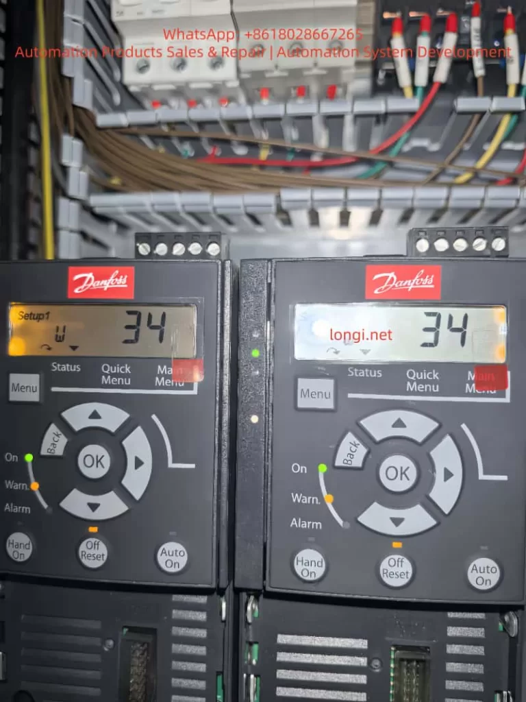
On the FC-360 Local Control Panel (LCP), “Setup1 W 34” or simply “34” accompanied by a yellow Warn indicator (while the green On light is on and the red Alarm light is off) indicates that the drive is powered on and outputting normally, but a communication problem has been detected on the fieldbus option card. The official manual clearly states:
WARNING/ALARM 34, Fieldbus communication fault
The fieldbus on the communication option card is not working.
This warning is triggered only when an optional fieldbus module (such as PROFIBUS DP MCA 101, PROFINET MCA 120, EtherNet/IP MCA 121, etc.) is installed. When using the built-in RS485 port (terminals 68/69) with FC protocol or Modbus RTU, W34 will not be triggered; W34 specifically refers to option card-level fieldbus faults. In a PROFIBUS environment, bit 15 (Warning 34 active) of parameter 9-53 Profibus Warning Word will be set, further confirming the source of the fault.
Unlike A34 (Alarm), W34 is a Warning level event. The motor can still run via digital inputs or local Hand On. However, if parameter 8-04 Control Timeout Function is set to [5] Stop and trip, it may escalate to an alarm later. In the actual display, the accompanying “Setup1” indicates that Setup 1 parameter set is currently in use and remote bus control has not been entered.
FC-360 Communication Architecture Overview: Built-in RS485 vs. Optional Fieldbus Option Card
The FC-360 comes standard with an RS485 interface (terminals 68 TX+/RX+, 69 TX-/RX-, 61 shield), supporting:
- Parameter 8-30 Protocol: [0] FC Communication or [2] Modbus RTU
- Parameter 8-31 Address: 1-126 (FC) / 1-247 (Modbus)
- Parameter 8-32 Baud Rate: 2400-115200
- Parameter 8-33 Parity/Stop Bits: Default Even Parity, 1 Stop Bit
These belong to the “FC Port” and will not trigger W34.
Optional Fieldbus option cards (installed in the control board expansion slot) include:
- MCA 101 PROFIBUS DP (Parameter group 9-** PROFIdrive)
- MCA 120 PROFINET
- MCA 121 EtherNet/IP
- MCA 122 Modbus TCP, etc.
After the option card is installed, if the drive detects during power-on self-check that the card exists but there is no master station telegram, address conflict, missing termination resistor, or physical disconnection, it will report W34. Parameter 8-00 Option A warning control can be set to [1] Disable Warning to temporarily mask it, but this is not recommended as a long-term solution.
In-depth Analysis of 8 Root Causes of W34 Fault
- Communication option card not connected to network or no master traffic
The most common cause for newly installed machines: The option card is installed from the factory, but the PLC/host computer is not wired or has not sent cyclic telegrams. The drive detects no valid data link and triggers W34. - Physical connection issues
Cable breaks, loose connectors, ungrounded shielding, reversed polarity (A/B lines or TX+/TX-). PROFIBUS requires a 120Ω termination resistor (one at each end); missing or incorrect resistance values will directly cause this fault. - Address conflict or node configuration error
Parameter 9-18 Node Address duplicates with the master station, or the PROFIBUS GSD file has not been correctly imported into the PLC. - Baud rate/protocol mismatch
Inconsistent baud rates between the master station and the option card (Parameter 9-63 Actual Baud Rate shows [255] No baudrate found). - EMC interference
Motor cables and bus cables laid in parallel without maintaining a 200mm distance, or poor shielding grounding, causing noise to destroy telegram CRC checks (Parameter 8-81 Bus Error Count increases). - Option card hardware failure
Rare, but includes damage to the internal ASIC chip of the card or poor slot contact. Manifested as a continuous accumulation of Parameter 9-44 Fault Message Counter. - Improper control word timeout configuration
Parameter 8-03 Control Timeout Time is too short (default 1s), and when 8-04 is set to non-[0] Off, a brief interruption will report W34. - Firmware/parameter initialization issues
Communication parameters are lost after replacing the main board, or synchronization initialization fails when multiple drives are connected in parallel.
Complete Diagnostic and Troubleshooting Process (Recommended Execution Order)
Step 1: Safety Confirmation and Initial Reset
Power off and wait 5 minutes (discharge time) to ensure the LCP display disappears. After repowering, immediately press the LCP “Off/Reset” key to clear. Set Parameter 14-20 Reset Mode to [0] Manual reset to ensure manual control.
Step 2: Check Option Card and Physical Connections
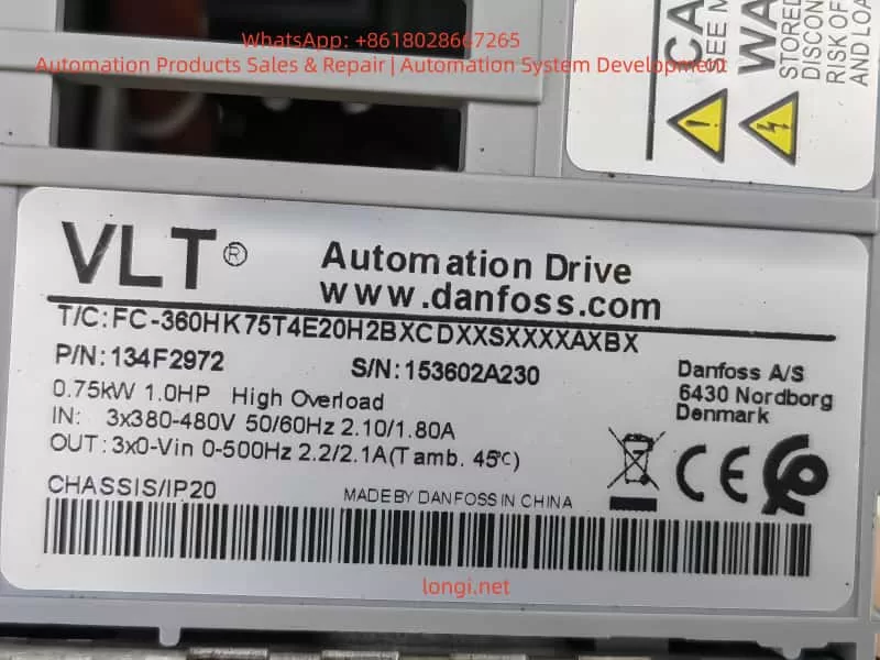
- Observe the drive label (T/C: FC-360H1K5T4E20H2B…) to confirm if there is an Option A (e.g., A0B indicates PROFIBUS).
- Power off and remove the option card (if not needed); restart to permanently eliminate W34.
- Use a multimeter to measure the bus cable resistance: PROFIBUS A-B should be approximately 120Ω (when terminated at both ends).
Step 3: Parameter Diagnosis (Enter 8-** and 9-** groups via Quick Menu)
- 8-00 Option: Set to [1] Disable Warning (temporary masking).
- 8-02 Control Source: Set to [0] None or [1] FC Port (switch to built-in RS485 to avoid option card control).
- 8-01 Control Site: [0] Digital and ctrl.word (hybrid digital + bus).
- Check 8-80 Bus Message Count (should increment) and 8-81 Bus Error Count (if > 0, there are CRC errors).
- PROFIBUS specific: Read 9-53 Profibus Warning Word in binary; if bit 15 is 1, it is W34; 9-63 Actual Baud Rate confirms the rate; execute [3] Comm option reset via 9-72 ProfibusDriveReset.
- Modbus TCP/PROFINET: Check 16-84 Comm. Option STW status word.
Step 4: Network Master Station Verification
- Confirm on the PLC side that GSD/EDS files are imported, and station numbers and I/O mapping are correct.
- Use a network analyzer to capture telegrams and confirm there are no “Clear data commands” or timeouts.
Step 5: EMC and Grounding Check
- Bus cables must be shielded twisted pairs (120Ω impedance), and the shielding layer should be grounded at single or multiple points with low resistance.
- Motor cables and bus cables should be laid crossing at 90° with a minimum spacing of 200mm.
- Set Parameter 14-50 RFI Filter to [0] Off (for IT grid) according to the grid type.
Step 6: Advanced Tool Diagnosis
Use Danfoss MCT 10 software (free download) to connect via USB or Ethernet:
- Read the alarm log (15-30 Alarm Log: Error Code).
- Monitor 9-52 Fault Situation Counter and 8-81 Bus Error Count online.
- Perform parameter backup/restore to rule out parameter loss.
If W34 is still reported, it is recommended to replace the option card or contact Danfoss service (provide serial number 331203A144, etc.).
Parameter Configuration Optimization: The Correct Way to Completely Eliminate W34
If fieldbus control is not required, the recommended permanent solution is:
- Power off and remove the option card (easy to operate for IP20 enclosures).
- Set Parameter 8-02 Control Source to [1] FC Port (use only built-in RS485).
- Set 8-04 Control Timeout Function to [0] Off (disable timeout action).
- Unify the 8-50~8-58 series (e.g., Coasting Select) to [3] Logic OR (digital input priority).
- After saving, execute 14-22 Operation Mode [0] Normal operation + restart.
If the option card must be retained:
- Select [0] FC profile or [1] PROFIdrive profile for 8-10 Control Word Profile.
- Set 9-22 Telegram Selection to [101] PPO 1 (standard telegram).
- Enable Parameter 9-28 Process Control [1] Enable cyclic master.
These settings can change W34 from a “continuous warning” to an “initial reminder only.”
Preventive Measures and Installation Best Practices
- Selection Stage: Clearly specify whether a Fieldbus option is needed when ordering (A0B in T/C code indicates PROFIBUS, etc.); select “X” for no option if not needed.
- Wiring Standards: Bus cables should be in separate conduits, isolated from power lines; termination resistors must be connected; shielding layers of all nodes must be reliably grounded.
- Power-up Sequence: Power on the PLC master station first, then the inverter, to avoid initialization desynchronization.
- Regular Maintenance: Check counters 8-81/8-85 quarterly and clear 8-88 Reset FC port Diagnostics.
- Environmental Control: Ambient temperature <45°C, humidity <95% RH, avoid dust (ensure ventilation for IP20 enclosures).
- Parameter Backup: Use MCT 10 to export .xml files for quick recovery.
Following these steps can reduce the W34 recurrence rate to nearly zero.
Actual Case Studies
Case 1 (Consistent with user scenario): A factory newly installed two FC-360 1.5kW units (serial number 331203A144), and W34 appeared immediately upon power-up. Inspection revealed that the PROFIBUS card was installed, but the PLC was not wired. After removing the card and setting 8-02 to FC Port, the warning disappeared, and the motor ran normally in Auto On mode.
Case 2: Caused by EMC interference. The bus cable was laid parallel to the motor cable for 10 meters, and the 8-81 counter reached several hundred. After rewiring and adding an equipotential cable, the errors were cleared.
Case 3: Address conflict. Multiple drives had their station numbers set to 126. After adjusting the 9-18 Node Address, the master station successfully established a connection.
FAQ: Frequently Asked Questions by Users
Q1: Will W34 cause a shutdown?
No, it is only a warning. The motor can still be controlled locally or via digital inputs.
Q2: How to permanently disable W34?
The most thorough method: Remove the option card; or set 8-00 to [1] Disable Warning + change 8-02 to digital control.
Q3: What is the difference in troubleshooting W34 between PROFIBUS and PROFINET?
For PROFIBUS, focus on checking the 9-** group and GSD files; for PROFINET, check the Web server diagnostics (built-in switch).
Q4: Is W34 inevitable for new machines?
Yes, as long as the option card is installed and there is no communication traffic.
Q5: How to connect MCT10 to FC-360?
Connect a USB-to-RS485 adapter to terminals 68/69, or use the option card Ethernet port.
Q6: What to do if W34 turns into A34?
Check the 8-04 setting, clear it, and manually Reset; if it persists, the option card has a hardware failure and needs replacement.
Q7: Will built-in Modbus RTU report W34?
No, it is only triggered by option cards.
Q8: What to do if the warning persists after changing parameters?
Execute 9-72 Comm option reset or power off the whole unit for more than 30 seconds.
Q9: How to download official FC-360 manuals?
Search for “FC 360 Programming Guide MG06C802” or “Design Guide AJ275647605270” on the Danfoss official website.
Q10: Is the card replacement free during the warranty period?
Provide the serial number and installation photos; a Danfoss authorized service center can evaluate the claim.
Summary and Recommended Resources
W34 is essentially a protection mechanism for “option card present but no communication,” which is almost inevitable for newly installed machines. It can be completely resolved by removing the card, switching parameters, or completing the network connection. Proper configuration not only eliminates warnings but also improves system reliability and EMC performance. It is recommended that every user download the latest FC-360 Programming Guide (for parameter details) and Design Guide (for installation specifications), and use the MCT 10 tool to achieve zero-fault operation.