
I. Introduction
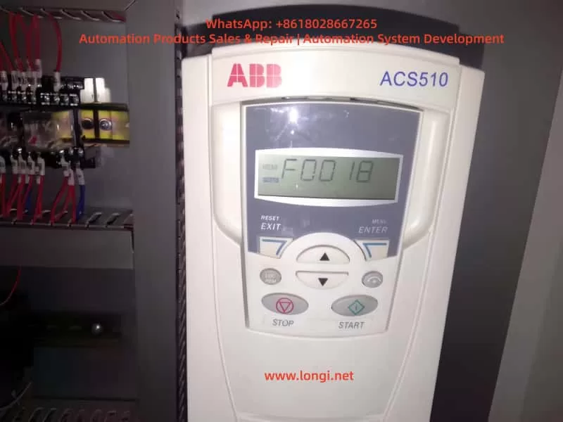
The ABB ACS510 series inverter is a widely used general-purpose drive in the industrial sector, renowned for its high reliability, ease of operation, and comprehensive protection functions. It serves as the core control component for equipment such as fans, pumps, and conveyors. However, during long-term operation, the F0018 fault (THERM FAIL) is a frequently encountered “tricky issue” for users. It not only causes sudden shutdowns, disrupting production continuity, but also requires precise troubleshooting due to its involvement with the core protection mechanism of “internal temperature monitoring.”
This article systematically analyzes the handling logic for F0018 faults from five dimensions: fault definition, hardware mechanisms, root cause analysis, troubleshooting steps, and resolution strategies, combined with practical cases. It aims to provide actionable operational guidelines for engineers and technical personnel.
II. The Essence of F0018 Fault: Failure of Internal Temperature Monitoring System
1. Fault Code Definition
According to the ABB ACS510 User Manual, F0018 corresponds to “THERM FAIL” (Temperature Sensor Fault), described as follows:
Internal fault. The internal temperature thermistor monitoring the drive is open or short-circuited. Please contact your local ABB office.
This fault is a hardware-level protection. When triggered, the inverter immediately blocks the output to prevent damage to power modules caused by overheating due to the failure of temperature monitoring.
2. Hardware Mechanism of Temperature Monitoring
The core of the ACS510 temperature monitoring system is an NTC Thermistor (Negative Temperature Coefficient Thermistor). Its characteristic is that resistance decreases as temperature increases (typically 10kΩ at 25°C, with a B-value of 3950K).
(1) Installation Location of the Thermistor
The thermistor is usually integrated into the power module (IGBT module) or mounted on the heat sink (as a discrete component in some models). It is in direct contact with the heat source to monitor the temperature of power devices in real-time.
(2) Monitoring Logic
The inverter’s CPU reads the resistance value of the thermistor via a voltage divider circuit and converts it into a temperature value (Formula: T=ln(R25RT)+298BB−273, where RT is the current resistance and R25 is the nominal resistance at 25°C).
- When the resistance exceeds the normal range (e.g., Open Circuit → Resistance ∞, Short Circuit → Resistance ≈ 0), or the temperature exceeds the threshold (default 90°C), the CPU triggers the F0018 fault.
- Critical Distinction: Difference between F0018 and “Overheat Fault (F0006)”:
- F0006: The temperature is genuinely too high (e.g., fan failure, blocked heat sink). The thermistor detects a temperature exceeding the threshold.
- F0018: The thermistor itself or the circuit is abnormal (e.g., open circuit, short circuit), causing the CPU to fail to read the temperature correctly.
III. Core Root Cause Analysis of F0018 Fault
The essence of F0018 is an abnormality in the thermistor monitoring loop. Specific causes can be categorized into four types: hardware damage, wiring issues, environmental factors, and parameter misconfiguration, with hardware damage being the most common (approx.60%).
1. Thermistor Damage (Most Common)
- Aging: Long-term exposure to high-temperature environments (e.g., frequent temperature fluctuations in power modules) causes the semiconductor properties of the NTC material to degrade. The resistance drifts (e.g., from 10kΩ to 20kΩ at 25°C) and eventually results in an open or short circuit.
- Mechanical Damage: Pins broken during installation, burned out during soldering, or broken due to vibration during operation.
- Overload Shock: Motor stall or short circuits cause a sudden temperature spike in the power module, damaging the thermistor due to excessive heat.
2. Wiring Connection Issues (Second Most Common)
- Loose Connections: Vibration during inverter operation loosens the screws of the thermistor terminals (e.g., X10, X20), causing poor contact (equivalent to an open circuit).
- Corrosion: In humid environments, terminal oxidation (e.g., verdigris) increases contact resistance. The CPU misinterprets this as an abnormal thermistor resistance.
- Broken Wires: Rodent bites, external pulling forces, or cold solder joints cause line breaks.
3. Cooling System Failure (Indirect Cause)
- Fan Failure: If the fan motor is damaged, the bearing is seized, or the fan power line fails (e.g., blown fuse), the heat sink temperature rises.
- Note: If the thermistor is functioning normally, this should trigger F0006, not F0018. F0018 is only triggered if the cooling failure causes the thermistor itself to overheat and fail.
- Blocked Heat Sink: Dust, pulp, or oil covering the heat sink prevents heat dissipation. The thermistor remains in a high-temperature environment for long periods, accelerating aging.
4. Environmental and Parameter Factors (Rare but Necessary to Check)
- Harsh Environment: Installation in dusty (e.g., textile mills), humid (e.g., sewage treatment), or hot (e.g., boiler rooms) environments causes the thermistor to absorb moisture or dust, leading to resistance anomalies.
- Parameter Misconfiguration: Users accidentally modify temperature monitoring parameters (e.g., setting Group 14, 1401 “Temperature Sensor Type” to “PTC”, or setting 1403 “Temperature Fault Threshold” to 50°C), causing the CPU to misjudge.
5. Power Module Failure (Associated Cause)
- IGBT Damage: When an IGBT shorts or breaks down, it generates massive heat, which may affect the thermistor (e.g., blowing the pins during an explosion), causing F0018 to trigger simultaneously with F0002 (Overvoltage) or F0003 (Undervoltage).
IV. Systematic Troubleshooting Steps for F0018 Fault
Troubleshooting F0018 must follow the principle of “Safety First, Simple to Complex, Hardware Priority.”
1. Safety Preparation (Critical!)
- Power Off: Disconnect the inverter’s input power (L1, L2, L3) and hang a “Do Not Energize” sign.
- Discharge: Use a multimeter to measure the DC bus voltage (+DC, -DC). Ensure it is below 36V (safe voltage) before proceeding. Note: The DC bus voltage of ACS510 is approx 1.35x the input voltage (e.g., 540V for 380V input). Wait 5-10 minutes for discharge.
- Verify: Use a voltage tester to confirm no voltage on the power side.
2. Visual Inspection (Quick Location of Obvious Issues)
Open the inverter front door and observe:
- Thermistor Appearance: Are the pins broken or burned? Is the body cracked? (If integrated into the power module, check for explosion marks on the module).
- Cooling System: Is the fan rotating? (If not fully powered down, briefly energize to observe). Is the heat sink covered in heavy dust or oil?
- Wiring: Are the thermistor terminals loose or oxidized (e.g., blackened terminals, loose screws)?
3. Thermistor Resistance Measurement (Core Step)
- Locate: Find the thermistor position according to the manual (usually labeled “TH,” “TEMP,” or near the power module).
- Tool: Use a digital multimeter (accuracy ≥ 0.5%) on the Resistance Range (20kΩ or 200kΩ).
- Method:
- Disconnect the thermistor from the inverter to avoid line interference.
- Measure the resistance between the two pins. At room temperature (25°C), the nominal value should be 10kΩ ± 10% (e.g., ABB spare part 1SFA896108R7000 is 10kΩ at 25°C).
- Hold the thermistor in your hand (simulate heating) and observe if the resistance decreases (NTC characteristic). If there is no change, the thermistor is damaged.
- Judgment Criteria:
- Resistance = ∞ → Open Circuit.
- Resistance ≈ 0 → Short Circuit.
- Resistance deviates from nominal by ±20% → Aged/Defective.
4. Line Continuity Check
- Tool: Multimeter Continuity Mode (Buzzer).
- Steps:
- Locate the thermistor terminals on the Control Board (CPU board) (e.g., X10-1, X10-2).
- Measure continuity between the terminal and the thermistor pin. If there is no beep, the line is broken.
- Check terminal torque (M3 screws should be 0.8-1.0 N·m). If loose, tighten and polish oxidation with sandpaper or alcohol.
5. Cooling System Check
- Fan Test:
- Disconnect the fan power plug.
- Measure voltage across the fan terminals (should be 24V DC or 380V AC depending on model).
- If voltage is normal but the fan doesn’t spin, the fan is damaged (replace with same model).
- If voltage is abnormal, check the fan power circuit (fuses, relays).
- Heat Sink Cleaning: Blow out dust from heat sink fins using compressed air (pressure ≤ 0.2 MPa) or brush with a soft brush. Caution: Do not touch sensitive components like power modules or capacitors.
6. Environment and Parameter Check
- Environment: If dusty, install a dust filter (clean every 1-2 weeks). If humid, install a dehumidifier or heater (maintain humidity ≤ 80%).
- Parameters: If misconfiguration is suspected, use Parameter 9902 (Reset to Factory Settings). Warning: This clears user-defined parameters; back up first.
7. Substitution Test (Final Verification)
If the above steps yield no results, replace the thermistor with a spare part of the same model (ensure model match: NTC 10kΩ/25°C, B-value 3950K).
- If F0018 clears, the original thermistor was damaged.
- If the fault persists, inspect the Control Board’s temperature monitoring circuit (voltage divider resistors, op-amps). Contact ABB or professional repair services at this stage.
V. Resolution Strategies and Case Studies
1. Solutions for Common Scenarios
| Fault Cause | Resolution Strategy |
|---|---|
| Thermistor Open/Short | Replace with same model (ABB Part: 1SFA896108R7000). Solder securely and tighten connections. |
| Loose/Oxidized Terminals | Polish oxidation, apply conductive grease, and tighten screws to specified torque. |
| Blocked Heat Sink / Fan Failure | Clean dust, replace fan, install dust filter. |
| Harsh Environment | Relocate to ventilated room; install dust/dehumidification equipment. |
| Parameter Error | Reset to factory settings (Param 9902); reconfigure essential parameters. |
| Associated Power Module Failure | Replace power module (e.g., 1SFA896107R7000 for ACS510-01-07A2-4) and thermistor. |
2. Practical Case Studies
Case 1: Chemical Plant Agitator Motor Inverter F0018
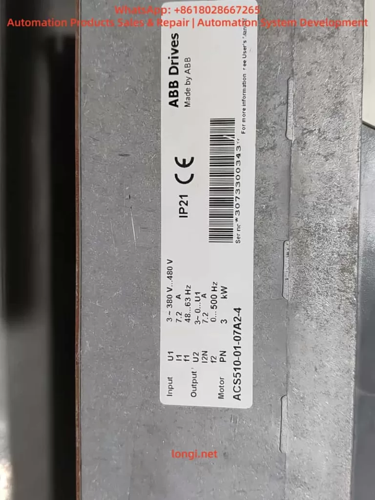
- Equipment: ABB ACS510-01-07A2-4 (7.5kW), driving an agitator in a chemical workshop (high dust).
- Phenomenon: Sudden stop during operation, displaying F0018.
- Troubleshooting:
- Safety: Power off, discharge. DC bus voltage confirmed 0V.
- Visual: Heat sink covered in chemical dust; fan jammed by dust. Thermistor pins intact but dusty.
- Resistance: Disconnected thermistor; measured ∞ (Open Circuit).
- Wiring: Terminals tight; continuity normal.
- Cooling: Cleaned dust from heat sink and fan; fan resumed rotation.
- Solution: Replaced thermistor (1SFA896108R7000), cleaned dust, installed dust filter.
- Result: Cleaning filter every 3 months; fault did not recur.
Case 2: Elevator Factory Inverter F0018
- Equipment: ABB ACS510-01-012A-4 (11kW), driving an elevator motor in a well-ventilated machine room.
- Phenomenon: F0018 triggered frequently; restart allowed brief operation.
- Troubleshooting:
- Safety: Power off, discharge.
- Visual: Heat sink clean; fan spinning normally. Thermistor pins OK.
- Resistance: Measured 15kΩ (should be 10kΩ at 25°C) – significant deviation.
- Wiring: Terminals oxidized, causing poor contact.
- Solution: Sanded terminal oxidation, applied conductive grease, tightened screws. Re-measured resistance: 10kΩ. Fault cleared upon power-up.
- Analysis: Oxidation increased contact resistance. The CPU read 15kΩ (implying ~15°C) while the actual temperature was normal. This logic contradiction triggered F0018.
3. When to Contact ABB Office
- The thermistor is integrated into the power module (common in compact models) and cannot be user-replaced.
- The cause cannot be determined after troubleshooting (e.g., suspected control board circuit failure).
- The inverter is under warranty (self-disassembly voids warranty).
- Calibration of the temperature system is required (e.g., high-precision monitoring in large drives).
VI. Preventive Measures for F0018 Fault
1. Regular Maintenance (Key)
- Every 1-3 Months: Clean heat sink dust, check fan operation, measure thermistor resistance (compare with nominal).
- Every 6-12 Months: Check terminal torque, clean oxidation, back up parameters.
- Every 2-3 Years: Replace fans (lifespan ~20,000 hours), test thermistor aging (replace if resistance deviates >10%).
2. Improve Operating Environment
- Install in a well-ventilated, dust-free, low-humidity location (Temp: -10°C ~ 40°C, Humidity: 10% ~ 80%).
- Avoid proximity to heat sources (motors, transformers); maintain ≥500mm clearance.
- Install dust filters (intake), dehumidifiers (humid), or air conditioners (hot).
3. Avoid Overload Operation
- Ensure motor load does not exceed inverter rating (e.g., 7.5kW inverter for 7.5kW motor; avoid sustained 10%+ overload).
- Set overload protection parameters (e.g., Group 15, 1501 “Overload Current Threshold” to 110% rated current) to prevent motor stalls.
4. Parameter Management
- Prohibit casual modification of temperature monitoring parameters (Group 14: 1401~1403).
- Regularly back up parameters using ABB Drive Composer software.
VII. Conclusion
The F0018 fault is a typical manifestation of internal temperature monitoring system failure in ABB ACS510 inverters. Its core cause is abnormality in the thermistor or its wiring. Troubleshooting should follow the logic of “Safety → Visual → Resistance → Wiring → Cooling → Environment,” prioritizing hardware issues (thermistor, wiring) before considering environmental or parameter factors.
Resolution strategies must be precise: replace hardware if damaged, repair wiring, or improve the environment. For integrated thermistors or complex circuit faults, contact ABB promptly to avoid further damage.
Prevention is paramount: Regular maintenance, environmental control, and avoiding overloads can reduce F0018 occurrence by over 80%. Mastering the troubleshooting logic outlined above enables engineers to restore production quickly and ensure equipment reliability.