
The ABB ACH580 series inverter, as a dedicated drive for HVAC applications, is widely used in fans, pumps, and air conditioning systems. Its stable operation directly impacts building energy efficiency and equipment lifespan. However, users frequently encounter the “2 faults active” panel alarm, accompanied by fault codes 7122 (Motor overload), 2340 (Short circuit), and 2281 (Current measurement calibration fault). Based on the ABB official firmware manual (ACH580 HVAC control program firmware manual), Calibration Fault 2281 technical note (LVD-EOTKN111U-EN), and actual field cases, this article systematically sorts out the causes, diagnostic logic, and troubleshooting steps of these faults to help engineers, maintenance personnel, and equipment owners quickly locate problems and avoid downtime losses.

Overview of ACH580 Inverter Fault Mechanism
The ACH580 adopts vector control technology with built-in high-precision current sensors to monitor the U/V/W three-phase output current in real-time. The fault protection logic is completed by the coordination of the control board and the power unit:
- 7122 Motor overload: Triggered when the motor thermal model (I²t) or measured current exceeds the threshold.
- 2340 Short circuit: The power unit detects an output short circuit or a mismatch in status feedback.
- 2281 Calibration: The current measurement offset or the difference between U2 and W2 phase values exceeds the limit (updated during calibration).
The panel displaying “2 faults active” indicates that at least two faults are activated simultaneously, often accompanied by an Aux code (such as 00000003 for 2281). These faults are not isolated; they often form a chain: motor/cable issues first trigger a 2340 short circuit, which causes current measurement inaccuracy triggering 2281, while load abnormalities叠加 a 7122 overload. This article will break them down one by one and provide an end-to-end diagnostic process.
In-depth Interpretation of Three Major Fault Codes
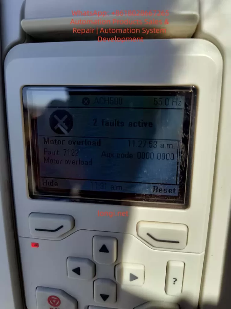
1. Fault 7122: Motor Overload
- Official Description (ACH580 Firmware Manual): Motor current is too high.
- Aux code: Usually 0000 0000.
- Trigger Conditions: Actual output current exceeds the motor’s rated value, or the cumulative I²t of the thermal model reaches 100%.
- Common Causes:
- Mechanical overload caused by fan/pump load jamming, bearing wear, or valves not opening.
- Ambient temperature > 40°C or motor cooling fan failure.
- Improper parameter settings: 35.51 Motor load curve, 35.52 Zero speed load, 35.53 Break point do not match the actual load curve; 35.55/35.56 action levels are too strict.
- Voltage fluctuations or unstable power supply amplifying current peaks.
- Risk: Continuous operation may burn out motor windings or IGBT modules.
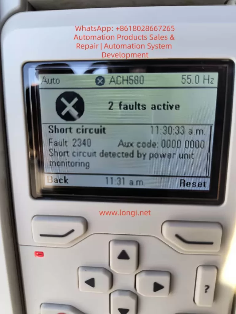
2. Fault 2340: Short Circuit
- Official Description: Short circuit in motor cable or inside the motor (monitored by the power unit).
- Aux code (Common in R6 and above models): 0001~0020 indicates IGBT upper/lower tube short circuit; 0080 indicates output phase status feedback mismatch with control signal; 0040 indicates DC bus capacitor short circuit.
- Trigger Conditions: Instantaneous sudden change in output current or phase-to-phase/ground resistance < specified value.
- Common Causes:
- Motor cable insulation damage, loose connections, aging, or rodent bites.
- Motor windings damp, burnt, or incorrect star-delta connection.
- Installation Taboo: Connecting power factor compensation capacitors or surge absorbers to the motor cable (explicitly prohibited by ABB).
- Cable is too long (>100m) causing capacitive current superposition.
- Chain Effect: The current peak at the moment of short circuit interferes with the sensor, easily inducing a subsequent 2281 calibration fault.
3. Fault 2281: Current Measurement Calibration Fault
- Official Description (ACH580/ACQ580/ACS580 Manual & LVD-EOTKN111U-EN Technical Note): The output phase current measurement offset is too large, or the difference between U2 and W2 phase measurements is too large (updated during calibration).
- Key Aux code Interpretation (ACH580 Specific Table):
- 0001: U-phase current offset too high.
- 0002: V-phase current offset too high.
- 0003: W-phase current offset too high (Typical for cases in this article, Aux code 00000003).
- 0004: Inter-phase gain difference is too large.
- Trigger Conditions: During power-up or ID run, the drive automatically calibrates the three-phase current sensors and detects a deviation exceeding the limit (typical threshold 0.5%~1%).
- Common Causes (Priority Order):
- Motor cable/W-phase wiring is loose, has poor contact, or is oxidized (accounts for 70% of field cases).
- Motor windings are asymmetrical, long cable capacitance effect, or ground fault.
- Power board current sensor hardware aging/damage (if reported even at no-load, 90% is this cause).
- Parameter Group 99 motor nameplate data does not match reality, or current calibration was not performed.
- Technical Essence: ACH580 vector control relies on precise current feedback (basis of Park transformation). W-phase offset causes torque ripple, efficiency drop, and even IGBT overheating.
Timeline Case Correlation: 11:27:53 triggered 7122 overload → 11:30:33 triggered 2340 short circuit → 11:32:07 triggered 2281 calibration (W-phase), fully conforming to the chain logic of “Load abnormality → Short circuit → Sensor inaccuracy”.
Root Cause Analysis and Logic Chain
Field data shows that when 2281 and 2340 appear simultaneously, over 90% originate from the motor side (cable/winding), not the drive hardware. The logic chain is:
- Cable/W-phase issue → 2340 short circuit protection.
- Transient current from short circuit disturbs sensor → 2281 calibration fails (especially W-phase).
- Load remains high → 7122 overload叠加.
Other Secondary Factors: Power supply harmonics, incorrect motor data in parameters 99.03~99.12, humid environment (common in US sites). If 2281 is still reported with the motor completely disconnected, the probability of hardware failure is >80% (power board or whole unit needs replacement).
Safety Precautions and Tool Preparation
⚠️ Mandatory Steps (Compliant with IEC 61800-5-1 and ABB Manual):
- Disconnect the main power supply and hang a “Do Not Energize” sign.
- Wait at least 5 minutes for the DC bus capacitors to discharge (measure UDC+~UDC- voltage < 30V).
- Use a 500V insulation resistance tester, multimeter, and clamp meter.
- Wear insulating gloves and confirm no residual voltage.
Prohibited: Unplugging motor cables while energized; resetting without discharging.
Step-by-Step Troubleshooting Process (Recommended completion time: 30~60 minutes)
Phase 1: Hardware Inspection (Isolate Root Cause, Execute First)
- Disconnect the motor cable (U/V/W+PE).
- Measure:
- Motor three-phase to ground insulation ≥ 5MΩ (500V range).
- Cable three-phase to ground ≥ 100MΩ.
- Focus on checking W-phase connector for burn marks, looseness, or oxidation.
- Visually inspect the cable for damage, oxidized connectors, or non-standard installation (vibration is common in US sites).
- Remove any PFC capacitors or surge protection devices from the motor cable.
Judgment:
- Low insulation → Replace cable/motor.
- Still reports 2281/2340 at no-load power-up → Drive hardware failure (contact ABB).
Phase 2: No-Load Test and Reset
- Disconnect motor cable, then power up.
- Enter
Diagnostics→Active faults, record all codes and timestamps. - Press “Reset” on the panel to clear.
- If faults disappear → Problem is on the load side; if still reported → Hardware or calibration parameter issue.
Phase 3: Perform Current Calibration (For 2281)
Parameter Path: 99.13 ID run requested.
- Set to “4 = Current measurement calibration” (Only supported by R6 and above; R1~R5 require a full ID run).
- Ensure the motor is disconnected or at no-load, then start calibration (panel shows progress).
- Restore 99.13=0 after success.
- If it fails → Check W-phase wiring and execute again; if it still fails, replace the unit.
Phase 4: Handle 7122 Overload
- Check actual load current (Panel 01.07 Motor current).
- Parameter Adjustment (Caution):
- 35.51~35.53: Optimize load curve (refer to motor nameplate).
- 35.55~35.56: Temporarily increase overload action threshold (but do not cancel protection).
- 35.57 Motor overload class: Set to 10 (IEC standard).
- Confirm motor ambient temperature < 40°C and cooling is good.
Phase 5: Comprehensive Test and Parameter Verification
- Gradual recovery: No-load test run → Light load → Full load.
- Monitor
Diagnostics→Fault history(last 5 faults + 20 events). - Verify Group 99 motor data (99.04~99.12) matches the nameplate.
- Enable auto-reset (31.12 Autoreset) only in safe applications (must mark “Auto-restart” warning).
Complete Flowchart Logic: Hardware Check → No-Load Reset → Calibrate 2281 → Adjust Group 35 → Full Load Verify → Record Logs.
Advanced Diagnostic Tips and Preventive Maintenance
Fault Data Recorder
The Drive Composer PC tool can capture 22,000 sampling points at 500μs intervals before a fault, precisely locking the current waveform at the trigger moment.
Preventive Strategies (Reduce recurrence rate by 80%)
- Annual Calibration: Perform 99.13 current calibration once a year.
- Cable Specification: Use shielded cables; add output filters (du/dt or sine filter) if length > 50m.
- Regular Inspection: Regularly measure insulation resistance and motor temperature (35.02/35.03).
- Wiring Isolation: Avoid running motor cables parallel to control lines.
- Environment Control: IP55 cabinet + anti-condensation heater.
- Parameter Backup: Use Drive Composer to export the complete parameter set.
Maintenance Cycle
- Monthly: Panel cleaning, fan inspection.
- Semi-annually: Insulation test + calibration.
- Annually: Full ID run (vector mode).
Case Study: ACH580 Field Fault for a US Customer
Site: A US HVAC site. The ACH580 panel showed “2 faults active” with timestamps in sequence:
- 11:27:53 → 7122 Motor overload
- 11:30:33 → 2340 Short circuit (Aux 00000000)
- 11:32:07 → 2281 Calibration (Aux 00000003, W-phase offset)
Diagnostic Process:
- Disconnected cable → Insulation was normal, but the W-phase connector was slightly loose.
- Tightened connection + Executed 99.13 current calibration → 2281 cleared.
- Adjusted 35.51~35.53 load curve → 7122 no longer triggered.
- Ran at full load for 24 hours without alarms; system restored.
Note: If 2281 is still reported at no-load, replace the drive directly (high probability of hardware failure).
Frequently Asked Questions (FAQ)
Q1: What does Aux code 00000003 specifically mean?
A: W-phase current offset is too high. Prioritize checking W-phase wiring and cables.
Q2: What to do if 2281 is still reported at no-load?
A: Drive current sensor or power board failure. Return to factory or replace the unit.
Q3: Can 2281 be temporarily masked?
A: No. Calibration failure leads to vector control inaccuracy, torque ripple, and even IGBT damage.
Q4: How to adjust parameters if 7122 triggers repeatedly?
A: Check the load first, then fine-tune the Group 35 curve; do not blindly increase 35.56.
Q5: Is the Drive Composer tool necessary?
A: Highly recommended for the fault data recorder and parameter backup.
When to Contact ABB Official Service
- 2281/2340 still reported during no-load testing.
- Calibration fails multiple times.
- Drive serial number is within warranty period ( provide nameplate photo, fault log, insulation measurement values).
- Complex applications (such as parallel operation or special motors).
ABB US local service responds quickly, usually providing on-site support or spare parts within 24~48 hours.
Conclusion: Closed-Loop Management from Fault to Prevention
The faults 7122, 2340, and 2281 of ACH580 seem complex, but they actually follow a clear logic of “Cable → Sensor → Load”. Mastering the 99.13 current calibration, Group 35 thermal protection, and systematic insulation testing can reduce downtime from days to hours. It is recommended that all users establish a “Fault Log + Annual Calibration” system and realize digital maintenance combined with the Drive Composer tool.