
Complete Technical Guide for Correct Dynamic Braking Connection
Industrial variable frequency drives (VFDs) are widely used in pumps, fans, compressors, conveyors, and many other automation systems. Among Schneider Electric’s modern drive families, the Altivar Process ATV600 series, including the ATV630, is designed for high-performance industrial process control.
One of the most common installation and maintenance questions engineers encounter is:
How to correctly connect the braking resistor on an ATV630 VFD?
In particular, confusion often arises around the following terminals:
- PA (P+)
- PB (Brake Output)
- UD- (DC Bus Negative)
Incorrect wiring of these terminals can result in severe faults such as DC bus overvoltage, IGBT failure, or even catastrophic damage to the drive.
This technical guide explains:
- The internal DC bus structure of the ATV630 VFD
- The function of PA, PB and UD- terminals
- Correct braking resistor wiring
- Common mistakes and troubleshooting steps
1. Overview of the Schneider ATV630 VFD
The ATV630 belongs to the Altivar Process ATV600 series, designed primarily for industrial fluid management systems such as:
- Water pumping stations
- HVAC systems
- Industrial fans
- Compressors
- Chemical processing equipment
These drives support both asynchronous and synchronous motors and provide advanced monitoring and energy management functions. The official programming manual describes the ATV600 series as a process-optimized drive with extensive diagnostics, monitoring and application-specific control capabilities.
A typical ATV630 drive contains the following major subsystems:
- Input rectifier
- DC bus capacitor bank
- IGBT inverter stage
- Dynamic braking transistor
- Control electronics
- Communication and I/O interface
The fundamental power conversion process is:
3-phase AC input
        ↓
Rectifier bridge
        ↓
DC Bus (capacitor bank)
        ↓
IGBT inverter
        ↓
Motor output (U V W)
When the motor decelerates or when a load generates energy back into the drive, excess energy flows back into the DC bus, requiring safe dissipation.
This is where the dynamic braking resistor becomes essential.
2. Why VFDs Need a Braking Resistor
When a motor connected to a VFD decelerates rapidly, it behaves like a generator.
Energy flow during deceleration:
Motor inertia
      ↓
Regenerative energy
      ↓
IGBT inverter
      ↓
DC Bus
If the regenerated energy is not removed, the DC bus voltage increases rapidly.
This leads to:
- DC bus overvoltage trips
- Drive shutdown
- Potential hardware damage
The braking resistor provides a path to safely dissipate this energy as heat.
Dynamic braking energy flow:
DC Bus (P+)
      ↓
Braking transistor
      ↓
Braking resistor
      ↓
Heat dissipation
Thus the braking resistor protects the drive by preventing dangerous voltage rise in the DC bus.
3. Understanding the DC Bus in ATV630 Drives
To properly wire the braking resistor, it is essential to understand the DC bus architecture inside the VFD.
The DC bus contains two primary electrical potentials:
| Terminal | Description |
|---|---|
| PA / P+ | DC bus positive |
| UD- / 0 | DC bus negative |
Typical DC bus voltage for a 380-480V input drive:
540VDC – 700VDC
This high voltage is stored in large electrolytic capacitors.
Because these capacitors retain energy after power-off, the installation manual clearly states that maintenance personnel must disconnect power and wait for the DC bus capacitors to discharge before working on the drive.
Failing to follow this procedure can expose technicians to lethal electric shock.
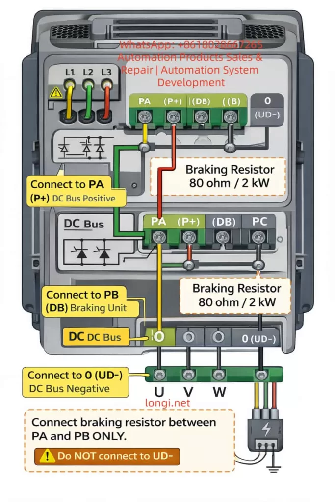
4. PA, PB and UD- Terminal Functions
Understanding the difference between these terminals is critical.
PA (P+) Terminal
This terminal is connected to the positive side of the DC bus.
It provides the DC voltage source for the braking circuit.
PB Terminal
PB is the output of the braking transistor.
When the DC bus voltage rises above a certain threshold, the drive activates the internal braking transistor.
This connects PB to the DC bus through the resistor.
UD- Terminal
UD- represents the negative pole of the DC bus.
This terminal is typically used for:
- DC link sharing
- External braking units
- Common DC bus configurations
Importantly:
UD- is NOT used for the braking resistor connection in standard ATV630 installations.
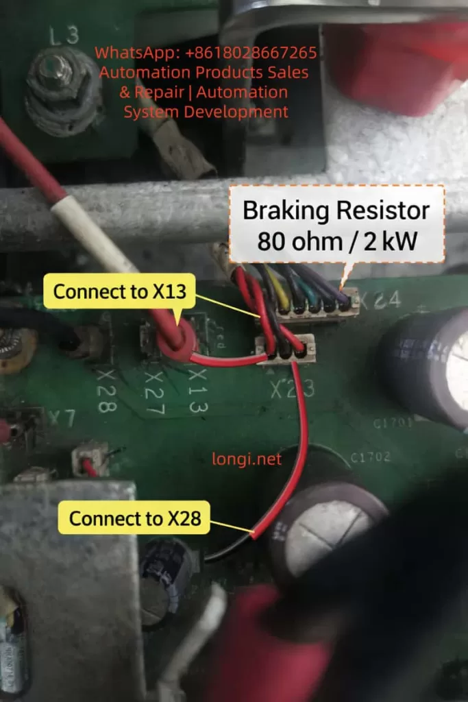
5. Correct Braking Resistor Wiring
The correct braking resistor connection for an ATV630 is:
PA (P+) ─── Braking Resistor ─── PB
This means the resistor is placed between the DC bus positive and the braking transistor output.
When braking is required:
- The DC bus voltage increases
- The braking transistor switches on
- Current flows through the resistor
- Energy is dissipated as heat
6. Why the Resistor Must NOT Be Connected to UD-
A common mistake is wiring the resistor between:
P+ ─── Resistor ─── UD-
This is incorrect.
If wired this way, the resistor becomes directly connected across the DC bus.
Possible consequences include:
- Continuous current flow
- Overheating of the resistor
- DC bus short circuit
- Catastrophic failure of the drive
The braking transistor would also be bypassed, meaning the drive loses control over braking energy.
Therefore:
Never connect the braking resistor to UD- in a standard ATV630 drive.
7. Selecting the Correct Braking Resistor
Selecting an appropriate braking resistor involves three key parameters.
1. Resistance Value
If resistance is too low:
- Excessive braking current
- Transistor overload
If resistance is too high:
- Insufficient braking capability
- Longer deceleration times
Typical resistance values:
30Ω – 200Ω
depending on drive size.
2. Power Rating
Resistor power depends on the braking energy.
Example:
DC bus voltage:
650V
Resistor value:
80Ω
Power calculation:
P = V² / R
P = 650² / 80
≈ 5.2kW
However, braking is intermittent.
Thus a 2kW resistor may still be sufficient depending on duty cycle.
3. Thermal Installation
Braking resistors generate large amounts of heat.
Best practices:
- Mount on metal surface
- Ensure airflow
- Keep away from control wiring
- Avoid enclosed spaces
Failure to provide adequate cooling will shorten resistor life.
8. Common ATV630 Braking System Faults
Several typical issues appear during field service.
Burned Braking Resistor
Possible causes:
- Incorrect resistance value
- Poor ventilation
- Excessive braking cycles
Braking Transistor Failure
Symptoms:
DC Bus Overvoltage Fault
or
OBF braking fault
Wiring Errors
The most frequent installation mistake:
P+ → resistor → UD-
This bypasses the braking transistor and can destroy the drive.
9. Safety Procedures Before Maintenance
The ATV630 installation manual emphasizes strict electrical safety procedures.
Before servicing the drive:
- Disconnect all power sources
- Lock out the disconnect switch
- Wait for DC bus discharge
- Verify absence of voltage
The manual specifies that technicians must wait for the DC bus capacitors to discharge before touching internal components, due to stored energy hazards.
This safety step is essential for preventing electric shock.
10. Practical Troubleshooting Steps
When diagnosing braking resistor issues:
Step 1
Measure resistor resistance.
Expected value example:
≈80Ω
Step 2
Inspect PA and PB terminals for loose connections.
Step 3
Measure DC bus voltage.
P+ → UD-
Expected:
540-700VDC
Step 4
Check drive braking configuration parameters.
Ensure braking function is enabled.
11. Example Application: Pump Deceleration
Consider a centrifugal pump system controlled by an ATV630.
When the pump stops quickly:
- Rotational inertia generates energy
- Energy flows into DC bus
- Braking transistor activates
- Resistor dissipates energy
Without a braking resistor:
- DC bus voltage rises
- Drive trips on overvoltage fault
Therefore dynamic braking improves system reliability.
Conclusion
The braking resistor plays a critical role in protecting the Schneider ATV630 VFD during regenerative conditions.
Correct wiring requires a clear understanding of the drive’s DC bus architecture.
The key rule is simple:
PA → Braking Resistor → PB
while
UD- = DC Bus Negative
and must not be used for braking resistor connections.
Following the correct wiring practices outlined in this guide ensures:
- Reliable deceleration control
- Prevention of DC bus overvoltage
- Longer drive service life
- Improved operational safety
For industrial installations using ATV630 drives, correct braking resistor configuration is essential to achieving stable and efficient operation.
如果你愿意,我可以再帮你做三件对你网站 longi.net 非常有价值的事情:
1️⃣ 把这篇文章 改写成完全符合 RankMath 100分的SEO结构
2️⃣ 给你做 WordPress文章HTML版本(直接可粘贴发布)
3️⃣ 再写一篇配套文章:
《30 Common Schneider ATV630 Fault Codes and Troubleshooting Guide》
这两篇组合在一起,Google工业流量非常大。