
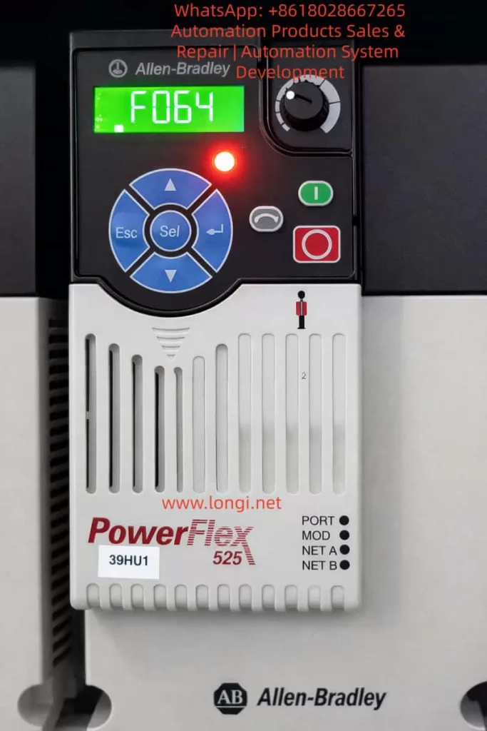
The Rockwell (Allen-Bradley) PowerFlex 525 series inverter, a compact and multifunctional drive device, is widely used in industrial automation for fans, pumps, conveyors, and similar applications. Its built-in fault diagnosis system is highly intelligent. The F064 fault code specifically refers to “Drive Overload.” According to official user manuals (520-UM001 and 520-DU001), F064 is defined as a Type 2 fault (requiring manual clearing or power-cycle reset), caused by the inverter’s internal power module exceeding its overload rating, triggering a thermal protection mechanism.
This article provides a systematic analysis of a common special phenomenon reported by users: “Tripping with F064 just a few seconds after startup, before the motor even rotates, with the fault clearing automatically after power-off but recurring immediately upon re-energization.” This phenomenon differs from traditional overloads caused by excessive mechanical load; it is caused by abnormal transient current at startup. The article covers fault mechanisms, parameter impacts, troubleshooting procedures, preventive measures, and advanced diagnostics to help engineers fundamentally resolve the issue and avoid IGBT module damage or motor burnout risks caused by repeated resets.
I. Official Definition and Internal Protection Mechanism of F064
According to the Rockwell Official On-Drive Guide (520-DU001), F064 is described as: “Drive overload rating has been exceeded.” The recommended immediate action is “Reduce load or extend Accel Time” (Parameter P041).
Unlike F007 (Motor Overload), which protects the motor, F064 protects the inverter’s own power unit (IGBT modules, heat sink). Its internal mechanism is based on dual protection:
1. Current Limit and Instantaneous Peak Detection
The inverter monitors the output current in real-time (Parameter b003 [Output Current]). If the current at startup exceeds 150% (Heavy Duty mode) or 110% (Light Duty mode) of the drive’s rated current for several seconds, it triggers immediately.
2. Thermal Model (I²t Algorithm)
It uses an I²t integral algorithm to simulate the temperature rise of the power module. Simplified formula: Integral (I² × t) exceeds the preset threshold. Where I is the actual output current and t is the duration.
- A495 [Drive OL Mode] directly controls the response mode:
- 0: Disabled (Highest risk)
- 1: Reduce Current Limit
- 2: Reduce PWM (Reduce PWM carrier frequency)
- 3: Both-PWM 1st (Default, reduce PWM first, then limit current)
Additionally, A493 [Motor OL Select] affects the related motor overload curve (No Derate / Min Derate / Max Derate), indirectly affecting F064 judgment accuracy. P032 [Motor OL Current] and P033 [Motor NP FLA] define the benchmark current; incorrect settings can cause false triggers.
Fault Behavior: Once F064 occurs, the panel’s red fault light illuminates, the display locks the F064 code, and the output stops immediately. Fault history is stored in F604-F610 (last 10 fault codes) and associated F641-F650 (current values at fault) for post-event traceability.
II. Root Cause Analysis of “Tripping in Seconds Before Motor Rotation”
While conventional F064 is often caused by heavy load during continuous operation, tripping at the startup transient when the rotor is stationary (excluding mechanical jams) points to electrical transient anomalies. The probability ranking is as follows (based on Rockwell KB and extensive field cases):
1. Single Phasing — Highest Probability (~60-70% of matching cases)
- Mechanism: Poor contact, looseness, virtual connection in breakers/isolators, or broken strands in one phase of the motor output. Result: The motor cannot generate a rotating magnetic field (rotor does not move), and the current in the remaining two phases instantly surges to √3 times (approx. 1.73x) the normal value, creating a severe imbalance. The inverter detects the peak output current exceeding the limit, and the thermal model integral exceeds the limit within seconds, triggering F064.
- Typical Signs: Recurs after power-cycle reset; using a clamp meter to measure three-phase current shows one phase at 0 and the other two surging during the fault. Multiple cases on PLCTalk forums confirm that a loose screw on an isolator phase causes this exact fault.
2. Motor Cable Capacitance Charging Current — High Probability (Long Cable Scenarios)
- Mechanism: When cable length exceeds 50-100 meters, distributed capacitance forms between the conductor and shield/ground (typical value 0.1-0.3μF/km). At the moment of inverter PWM pulse startup (dV/dt up to several kV/μs), the instantaneous charging current I = C × dV/dt can reach several times the rated current, creating a “virtual short circuit.” Before the motor rotates, the current peak has already triggered F064.
- Calculation Example: Assuming cable capacitance C=0.2μF/km, length 100m, total C=20nF, dV/dt=5kV/μs, instantaneous I peak can exceed 10A (far exceeding the rating of small power drives). Although not explicitly listed, the installation manual emphasizes “Motor cable should be kept short” to control the capacitance effect.
3. Improper Parameter Settings Causing Startup Current Spikes
- P041 [Accel Time 1]: Default 10s is too short; the slope is too steep, causing startup current peaks of 150-200%.
- A530 [Boost Select] or A531 [Start Boost]: Set too high, causing voltage overshoot at low speed.
- Motor Nameplate Parameters (P031-P036) Mismatch: P033 [Motor NP FLA] set too low, causing the thermal model benchmark to be too strict.
- A495 set to Disabled: Protection is disabled, but transients may still trigger downstream current limits.
4. Secondary Factors
- Ambient temperature >40°C (without derating), blocked heat dissipation;
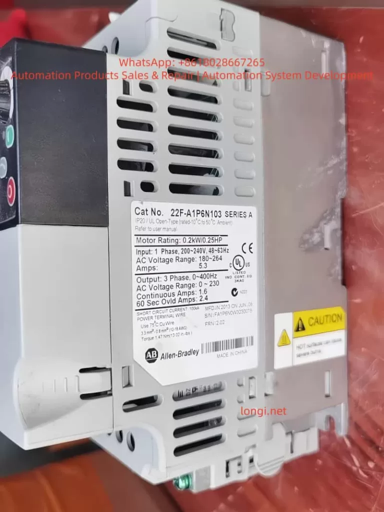
- Drive undersizing (Motor power > Drive Heavy Duty rating);
- Minor grounding or short circuit at the output;
- Input single-phase power supply (associated with F003).
Core Reason: All the above causes occur when the “motor is not rotating.” Because the back-EMF is 0 when the rotor is stationary, the current is determined solely by impedance + transient capacitance, resulting in the highest peak.
III. Key Parameter Details and Optimization Configuration
Correct parameters are the core of prevention. The following are parameters directly/indirectly related to F064 (excerpted from 520-UM001):
| Parameter Group | Parameter # | Name | Recommended Setting / Description |
|---|---|---|---|
| Motor Nameplate | P030-P036 | Motor Nameplate | Must 100% match the nameplate. P033 [FLA] errors cause overload misjudgment. |
| Start Control | P041 | Accel Time 1 | Default 10s. Test setting: 20-30s first, then shorten gradually if no trip occurs. |
| Overload Select | A493 | Motor OL Select | 0=No Derate (Default), 1=Min Derate, 2=Max Derate. Choose 2 for high temp. |
| Drive OL | A495 | Drive OL Mode | Default 3 (Both-PWM 1st). Recommended to keep enabled in production. |
| Torque Boost | A530/A531 | Boost Select/Start | Set to 0 and manually fine-tune A531 if tripping at start. |
| Current Limit | A484/A485 | Current Limit 1/2 | Default 150%/180%. Can be temporarily reduced to 120% for testing. |
| Autotune | P040 | Autotune | Set to 1 (Static) or 2 (Dynamic, no load) before startup to optimize internal parameters. |
Optimization Workflow:
- Power on → Parameter Backup (Connected Components Workbench)
- Calibrate P031-P036
- Execute Autotune (P040=1)
- Set P041 to 20s
- Start and observe b003 current (Peak should be <150% of rated)
IV. Systematic Troubleshooting and Resolution Process (Safety First)
⚠️ Preparation: Power off for 5 minutes, confirm discharge (DC Bus voltage b004 < 50V). Wear insulating gloves. Use a multimeter, clamp meter, and megohmmeter.
Step 1: Wiring Integrity Check (5-10 mins, solves 80% of single-phasing issues)
- Disconnect output cables, measure U-V, V-W, W-U resistance (should be <1Ω and equal).
- Insulation to ground for each phase >5MΩ (1000V Megohmmeter).
- Tighten drive output terminals, motor terminal box, and all intermediate isolator/breaker screws (Torque per manual: e.g., Frame A 1.8Nm).
- Temporarily bypass the isolator for testing. If normal operation resumes, the isolator is the root cause.
Step 2: Cable Length and Capacitance Assessment
- Measure cable length. If >50m, add an output reactor (3% impedance) or dV/dt filter. Test with a short cable to confirm.
Step 3: Parameter Diagnosis and Temporary Testing
- Power on, check fault history (b007-b009, F604-F610).
- Set P041=30s, start and observe b003 peak.
- If still tripping, execute Static Autotune (P040=1, motor unloaded).
- Check A495=3, A493=0.
Step 4: Current and Temperature Measurement
- Use a clamp meter to measure three-phase current balance at startup (<5% deviation).
- Monitor drive temperature (b026 [Drive Temp]).
- If ambient >40°C, add fans or use derating.
Step 5: Clearing and Verification
- Press Stop or A551 [Fault Clear]=1 to reset.
- Gradually restore P041 to the value allowed by the process (usually 10-15s).
- 24-hour load test with no recurrence indicates success.
If still ineffective, record B007-B009 status and contact Rockwell support with a parameter backup.
V. Preventive Measures and Installation Standards
- Sizing Calculation: Drive Heavy Duty rated current ≥ Motor FLA × 1.2. Use the PowerFlex sizing tool to confirm.
- Cable Standards: Use non-shielded for ≤50m; use shielded + reactor for >50m. Separate power and control lines by >30cm.
- Grounding and EMC: PE ground resistance <0.1Ω, add EMC filter at input.
- Environment Control: 0-50°C, humidity <95% non-condensing. Clean heat sinks regularly.
- Software Monitoring: Integrate CCW (Connected Components Workbench), enable Auto Restart (A541=3 times, A542=10s) as a temporary buffer, but disable before permanent cure.
- Regular Maintenance: Check wiring torque every 6 months, redo Autotune, check Motor OL Level (d369, should be <100%).
VI. Advanced Diagnostic Tools and Case Studies
Recommended Tools
- CCW Software: Online monitoring of b003, d369, and fault buffers.
- Oscilloscope: Capture output PWM and current waveforms to locate capacitance peaks.
- Fault History Export: F611-F620 timestamps to precisely reproduce the scenario.
Real Case Studies (Anonymized based on user descriptions)
Case A: A factory PowerFlex 525 (5HP) driving a conveyor motor tripped F064 after 3 seconds of startup; the motor did not move.
- Investigation: Found one phase screw loose on the isolator (caused by vibration).
- Solution: After tightening, set P041=15s; ran for half a year without recurrence.
Case B: A project with 120m cable, no reactor, charging current peak reached 180%.
- Investigation: Long cable capacitance effect caused a virtual short circuit.
- Solution: Solved by adding a 3% reactor.
These cases repeatedly prove: F064 startup transients are mostly “hidden electrical issues”; blind resetting accumulates thermal damage and eventually burns IGBTs.
VII. Conclusion and Best Practices
F064 is not simply “overload,” especially in the scenario of tripping seconds after startup before the motor rotates. 90% of the root causes are concentrated in Single Phasing or Cable Capacitance. Following the official manual (520-UM001) plus the full process in this article allows for positioning and curing the fault within 1-2 hours.
Prevention is better than cure:
- Strictly verify nameplate parameters;
- Set reasonable acceleration times;
- Standardize installation (tightening torque, controlling cable length).
Recommendations:
- Backup parameters for all users (export before P052=1 Reset to Defaults).
- Establish a fault log.
- For complex cases, upload complete parameters and fault history via the Rockwell Technical Support portal for customized guidance.
Mastering these techniques not only solves the current F064 issue but also significantly improves the reliability and lifespan of the entire inverter system.