
Introduction
In the field of industrial automation, Human-Machine Interface (HMI) devices like Schneider Electric’s Magelis XBTGT6330 play a critical role. They not only provide an intuitive operating interface but also integrate controller functions to support real-time monitoring and data interaction. However, when equipment ages or fails, backing up programs from old screens and transplanting them to spare units becomes a common challenge for maintenance engineers.
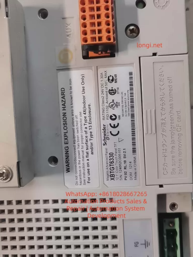
The XBTGT6330 is a 12.1-inch TFT advanced touch screen that supports Compact Flash (CF) cards, USB, and Ethernet interfaces. Program transfer involves backing up runtime applications, uploading source projects, and, in extreme cases, hardware-level FLASH chip cloning. Based on Schneider’s official guides and practical maintenance experience, this article systematically explains the technical principles, operational steps, potential risks, and optimization strategies of these methods to help users handle program migration efficiently while avoiding data loss or equipment damage.
XBTGT6330 Specifications:
- Display: SVGA resolution (800×600 pixels), 65,536 colors
- Memory: 32MB Application Flash, 64MB DRAM
- Protocols: CANopen extension, COM1 (RS232C/RS422/RS485), COM2 (RS485)
- Storage Mapping: Designed to minimize address differences between controller and HMI, but backups require strict protocol adherence to prevent checksum errors.
XBTGT6330 Hardware Structure & Storage Mechanism
Understanding the hardware of the XBTGT6330 is the foundation of program transplantation. The device uses an embedded architecture with a motherboard integrating the CPU, DRAM, SRAM, and Flash memory chips.
1. Core Components
| Component | Specification | Function |
|---|---|---|
| Display | 12.1″ TFT, SVGA 800×600 | Touch operation interface |
| Flash Memory | 32MB NOR EPROM (TSOP48) | Stores runtime programs |
| CF Card Slot | TYPE-II, Supports 128MB-2GB | Backup/Restore applications |
| DIP Switch | 4-bit, under CF cover | Controls loading mode |
- Flash Memory: Typically a NOR-type EPROM in a TSOP48 package. It stores the complete runtime image, including the interface, logic, and variable mapping.
- SRAM: Used for real-time data retention, powered by a lithium battery (approx. 10-year lifespan).
- CF Card Slot: It is recommended to use original Schneider cards (e.g., XBTZGM128) to ensure compatibility and endurance (approx. 100,000 write cycles).
- DIP Switch: Located under the CF card cover. Setting DIP1 ON enables download mode from the CF card.
2. Interface & Boot Mechanism
- Interfaces: USB (for Vijeo Designer), Ethernet (for FTP), Serial (for Modbus/Uni-Telway).
- Boot Process: Upon startup, the device verifies the integrity of the Flash memory. If an inconsistency is detected (e.g., CRC mismatch), it may enter an error state (External Error).
⚠️ Maintenance Tip: Non-original CF cards may cause data corruption. Always observe ESD (Electrostatic Discharge) protection and power-off procedures during maintenance.
Method 1: Program Backup & Transfer via CF Card
The CF card is the safest and most common method for program transfer, especially when the source project file is unavailable. It backs up the Runtime Application, not the editable .vdz source file, based on the device’s Data Manager.
Backup Steps (Source Screen)
- Prepare CF Card: Ensure compatibility (Original Schneider XBTZGM64/128 recommended). Insert the card while the device is powered off.
- Enter Offline Mode: Power on while holding the top-right corner of the screen or use the function keys to access the System Menu.
- Execute Backup: Navigate to
Data Manager>Backup>Application.- The backup creates a runtime image in the CF card’s
\SFlashdirectory.
- The backup creates a runtime image in the CF card’s
- Verify: Check the CF card access LED (Green ON indicates activity). Power off and remove the card once complete.
Transfer to Spare Screen
- Insert CF Card: Insert the backup card into the spare XBTGT6330 (Note: Model, PV, RL, and SV versions must match).
- Set DIP Switch: Open the CF cover and set DIP1 to ON (Enables download from CF).
- Power On & Load: The device automatically restores the program from the CF card to internal Flash.
- Reset & Test: After loading, reset DIP1 to OFF, power cycle, and verify the interface and logic.
💡 Expert Note: Forum experience suggests that if the old screen has no CF card, you can buy a new one and insert it to perform the backup. This method does not require Vijeo Designer and is ideal for on-site quick repairs, though it does not allow for source code editing.
Method 2: Uploading Projects via Vijeo Designer
Vijeo Designer (Version 6.2 or higher) is Schneider’s official HMI programming tool, supporting project uploads via USB, Ethernet, or Serial ports.
1. Upload Conditions & Limitations
- Prerequisite: During the original download, the option “Include Editor Project” must have been checked, and the data location set to Secondary Drive (CF) or Optional Drive (USB).
- Limitation: If this option was not checked, you can only upload runtime data, not the editable source file. Attempting to upload will result in errors like “NO CF card found.”
- Irreversibility: Runtime applications cannot be reverse-engineered into source projects. You must contact the original developer or reconstruct the project.
2. Upload Steps
- Physical Connection:
- Priority: Use the XBTZG935 USB Cable.
- Alternative: Enter the HMI IP address via Ethernet.
- Software Operation: Launch Vijeo Designer > Right-click “Vijeo Manager” > “Upload Editor Project”.
- Select Connection: Match the settings used during the download (USB/Ethernet/Serial).
- Execute Upload: The software extracts the
.vdzfile from the CF card or USB. - Verify: Run a simulation on the PC to check integrity.
3. Connection Comparison
| Connection Type | Advantage | Notes |
|---|---|---|
| USB | Fast, Simple | Requires dedicated cable (XBTZG935) |
| Ethernet | Remote operation | Requires IP configuration |
| Serial | Compatible with legacy devices | Slow speed |
Method 3: FLASH Chip Transplant (Hardware Cloning)
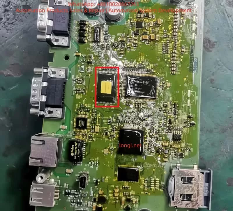
When the CF card is unavailable or backup fails, hardware-level FLASH chip cloning is often used in repair scenarios. This involves desoldering the TSOP48 Flash chip, dumping its data, and writing it to a new chip.
1. Principle
- Chip Type: NOR Flash (e.g., Samsung K9F series) in a TSOP48 package.
- Mechanism: Cloning copies the entire binary image, including the bootloader and data. However, the system verifies the Checksum/CRC during boot. If they don’t match, an error is triggered.
- Encryption: The XBTGT series generally relies on integrity checks rather than strong AES encryption or device binding, making cloning feasible on identical hardware.
2. Required Tools
- FLASH Programmer: MiniPro TL866II or CH341A (supporting TSOP48).
- Soldering Equipment: Hot air gun (set to 300-350°C) or rework station.
- Software: Hex Editor (e.g., HxD) for checksum repair.
- Safety: ESD wrist strap and heat shields.
3. Detailed Procedure
- Disassemble: Power off, remove the motherboard, and use a hot air gun to remove the TSOP48 Flash chip.
- Read Data: Insert the old chip into the programmer, select “Read” mode, and dump the full image as a
.binfile. - Write New Chip:
- Desolder the chip from the spare screen or use a new compatible chip.
- Select “Program” mode to write the
.binfile. Enable “Verify” to ensure accuracy.
- Soldering: Resolder the chip to the board using SMT techniques, ensuring no bridging or cold joints.
- Test: Power on. If the screen boots into the normal runtime, the transplant is successful.
4. Handling Checksum Issues (Critical)
- CRC Mechanism: The system compares the Flash content with a calculated value in RAM. Mismatches cause boot failures.
- Repair:
- Use programmer software to auto-calculate checksums.
- Manual Method: Open the
.binin HxD, analyze the offset (usually the last 4-8 bytes), and correct the value. Reference CRC polynomials from similar devices (e.g., STM32 often uses0x04C11DB7).
Checksum Mechanism: Deep Dive & Strategies
The XBTGT6330 uses CRC (Cyclic Redundancy Check) and Checksum to detect data integrity in Flash memory.
Common Issues & Solutions
- Cloning Bit Errors: Use the programmer’s “Verify” function multiple times to ensure the binary is identical.
- Header Mismatch: Edit the
.binfile to repair the CRC using tools likehex2000. - Configuration Differences: If the Flash contains a serial number, use Vijeo Designer to force a blank application overwrite before loading the cloned image.
⚠️ Warning: If the checksum algorithm is unknown, forcing a write may cause the system to loop-reboot. Software recovery methods are always preferred over hardware cloning unless performed by a professional.
Risk Assessment & Best Practices
1. Risks
- Hardware Damage: ESD strikes or excessive heat can permanently destroy the PCB.
- Compatibility: Differences in hardware versions (PV/RL) can cause memory mapping errors.
- Data Loss: Checksum failure renders the device unbootable, losing SRAM data.
- Legal: Reverse engineering may violate IP rights.
2. Best Practices
- Regular Backups: Always check “Include Editor Project” when downloading and archive
.vdzfiles locally. - Original Parts: Use Schneider-certified CF cards and USB cables.
- Test Environment: Verify transplanted programs on a spare screen or simulator first.
- Documentation: Refer to the Magelis XBT GT Programming Guide and Hardware Guide.
- Professional Help: If inexperienced, contact a Schneider Authorized Service Center.
Case Studies
- Case 1 (CF Transfer): A factory’s old XBTGT6330 failed without a source project. An engineer used a CF card to backup the runtime, transferred it to a new screen via DIP switch, and restored production in 5 minutes.
- Case 2 (Flash Cloning): The Flash chip was physically damaged. The chip was desoldered, dumped using a TL866II, and written to a new chip. The checksum was repaired using HxD. The device booted successfully, though SRAM data had to be manually reset.
- Case 3 (Upload Failure): Vijeo Designer upload failed because “Include Editor Project” was not checked during the original download. The user had to export the configuration via USB and reverse-engineer the logic, taking 2 days. This highlights the importance of prevention.
Future Trends & Alternatives
- Cloud Backup: With Industry 4.0, newer Schneider series (e.g., Harmony GTO) support wireless/cloud backups, reducing hardware dependency.
- Software Integration: EcoStruxure Machine SCADA Expert offers integrated remote management.
- Hardware Upgrades: Upgrading to the HMIGTO series allows compatibility with old programs while offering better encryption (AES).
- AI Diagnostics: AI-assisted tools are emerging to predict Flash memory failure and automate checksum repair.
Conclusion
Backing up and transplanting programs for the Schneider Magelis XBTGT6330 requires a combination of hardware and software expertise.
- First Choice: CF Card (Safest, fastest for field repair).
- Second Choice: Vijeo Designer Upload (Requires pre-configuration).
- Last Resort: FLASH Chip Cloning (Requires professional tools and checksum repair).
Understanding the checksum mechanism and strictly following operational protocols are key to ensuring system reliability and minimizing downtime in industrial environments.