
1. Fault Description
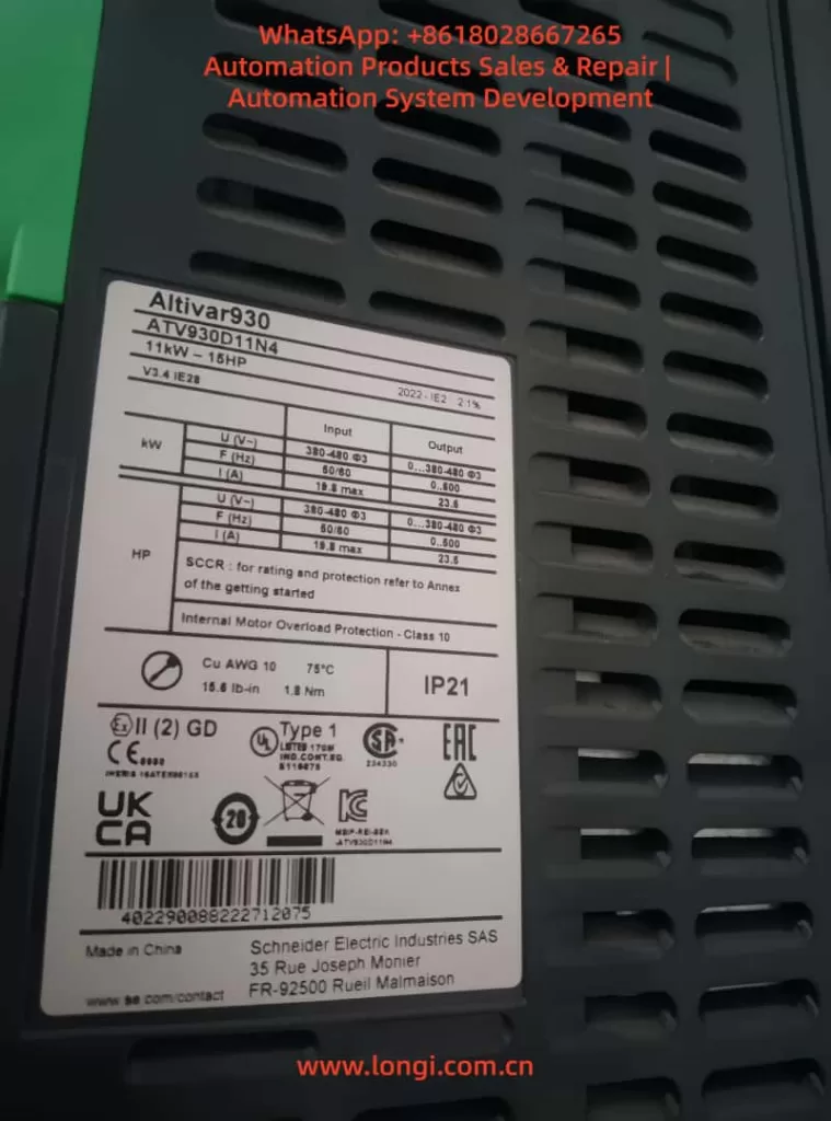
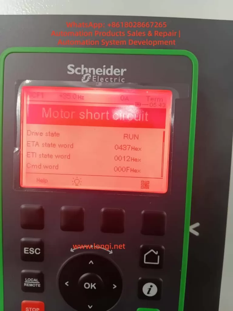
The photo shows a Schneider Electric Altivar Process ATV930 drive displaying the fault message:
Motor short circuit
This means the inverter has detected a short-circuit type abnormality on the motor output side. It does not always mean the motor winding is definitely shorted, but it means the drive has detected an output current condition that matches a motor-side short circuit, phase-to-phase fault, phase-to-ground fault, abnormal leakage, incorrect output wiring, or internal power module problem.
This is a serious fault. The drive should not be repeatedly reset and restarted before inspection, because forced restarting may damage the IGBT module, gate driver board, current detection circuit, DC bus components, or motor cable.
2. What This Fault Means
The ATV930 outputs three-phase PWM voltage through the U, V, and W terminals. Under normal conditions, the output current follows the motor load, acceleration demand, frequency, and torque requirement.
When the drive detects an abnormal current rise, current imbalance, or short-circuit pattern, it trips with Motor short circuit.
Possible meanings include:
- Motor winding phase-to-phase short circuit.
- Motor winding insulation failure to ground.
- Damaged or wet motor cable.
- Loose, burned, or carbonized motor terminal box.
- Output cable shield touching phase conductors.
- Incorrect wiring on U/V/W output terminals.
- Output contactor or output filter fault.
- Mechanical load locked or jammed.
- Motor parameters set incorrectly.
- IGBT module or gate driver circuit failure inside the drive.
- Current sensor or current detection circuit fault.
Therefore, this fault must be diagnosed step by step. It is wrong to immediately conclude that only the motor is bad or only the drive is bad.
3. Main Causes of “Motor Short Circuit” on ATV930
3.1 Motor winding short circuit
A phase-to-phase short circuit inside the motor winding can cause very high output current when the drive starts. The drive then trips immediately.
Basic checks:
- Measure U-V, V-W, and W-U resistance.
- The three readings should be balanced.
- For large motors, use a milliohm meter instead of a normal multimeter.
- If one phase pair is obviously lower than the others, the winding may be shorted.
- If the readings are close but suspicious, use a surge/turn-to-turn tester.
A standard multimeter may not detect turn-to-turn short circuits in large motors, because the normal winding resistance is already very low.
3.2 Motor insulation failure to ground
This is one of the most common causes. Motors used in pumps, fans, cooling towers, compressors, outdoor equipment, and humid environments often suffer insulation degradation.
The motor may still run on a normal mains supply, but fail when powered by a VFD. This is because the inverter output contains high-frequency PWM pulses, high dv/dt, and common-mode voltage, which stress weak insulation more severely.
Use a megohmmeter to test:
- U to ground
- V to ground
- W to ground
- U-V
- V-W
- W-U
Before testing, disconnect the motor cable from the inverter. Never apply megger voltage into the inverter output terminals.
For low-voltage motors, insulation should generally be well above 1 MΩ. In practical industrial maintenance, a healthy motor is usually expected to show several MΩ, tens of MΩ, or higher. If the insulation is only hundreds of kΩ or close to zero, the motor must not be connected back to the drive for trial running.
3.3 Damaged motor cable
The motor cable is often the real cause, especially in harsh industrial environments.
Common cable problems include:
- Damaged outer sheath.
- Cable crushed by machinery.
- Water inside cable tray.
- Aging insulation.
- Burned cable lugs.
- Shield layer touching phase wires.
- Poor cable termination.
- Copper strands left loose inside the terminal box.
- Metal dust or carbonized contamination causing leakage.
A useful test is to separate the motor and cable, then test them independently. If the motor insulation is good but the cable insulation is bad, replace the cable or remake the cable termination.
3.4 Motor terminal box problem
A wet or carbonized terminal box can easily trigger a short-circuit fault.
Check for:
- Water ingress.
- Burn marks.
- Cracked terminal board.
- Loose screws.
- Oxidized cable lugs.
- Carbon tracking.
- Oil, dust, or metal particles.
- Cable shield touching live terminals.
- Poor grounding.
If the terminal board is carbonized, cleaning is often not enough. Carbonized material can continue to conduct and cause leakage. Replacement is recommended.
3.5 Output-side contactor, filter, or reactor problem
The output side of a VFD is not the same as a normal mains supply. The U/V/W terminals output high-frequency PWM voltage. Improper components connected to the output can cause short-circuit faults.
Problematic cases include:
- Power factor correction capacitors connected on the inverter output.
- Output contactor switching while the inverter is running.
- Damaged output reactor.
- Faulty sine filter or dv/dt filter.
- Incorrect multi-motor switching circuit.
- Contactor contacts welded or carbonized.
- Output terminal block damaged.
If an output contactor is used, it must be interlocked so that it only opens or closes when the inverter output is disabled.
3.6 Mechanical load jammed
A locked mechanical load can cause very high starting current. This may be interpreted by the drive as a short-circuit type fault, especially if the acceleration time is too short or the torque boost is too high.
Typical mechanical causes:
- Pump impeller jammed.
- Fan bearing seized.
- Gearbox locked.
- Conveyor blocked.
- Compressor seized.
- Screw pump stuck.
- Mixer blocked by solidified material.
Disconnect the motor from the mechanical load and run the motor alone. If the motor runs normally without the load, the mechanical system must be inspected.
3.7 Incorrect motor parameters
The ATV930 depends heavily on correct motor data. Incorrect motor parameters can cause abnormal current during starting or acceleration.
Check:
- Motor rated power.
- Motor rated voltage.
- Motor rated current.
- Motor rated frequency.
- Motor rated speed.
- Power factor.
- Motor control mode.
- Acceleration time.
- Torque boost.
- Current limit.
- Auto-tuning result.
If the motor or drive was replaced recently, enter the motor nameplate data again and perform motor auto-tuning. If the motor can be disconnected from the load, rotating auto-tuning is usually better. If the load cannot be disconnected, use static auto-tuning if supported.
3.8 Internal inverter fault
If the motor cable is disconnected from U/V/W and the drive still reports Motor short circuit, the fault is likely inside the inverter.
Possible internal faults include:
- IGBT module short circuit.
- One output phase shorted to DC+ or DC-.
- Gate driver circuit fault.
- Gate resistor open or damaged.
- Driver power supply abnormal.
- Current sensor offset or failure.
- Current detection amplifier fault.
- Control board or power board communication problem.
- Moisture or conductive dust on the power board.
In this case, do not continue trial operation. The drive should be inspected at component level.
4. Correct Troubleshooting Procedure
Step 1: Stop repeated reset attempts
Do not repeatedly reset and restart the ATV930. A real output short circuit can destroy the power module.
Proper first action:
- Stop the drive.
- Switch off the main supply.
- Wait for the DC bus to discharge.
- Measure DC+ and DC- voltage.
- Confirm the voltage is safe before touching wiring.
Step 2: Record the fault conditions
Before clearing the fault, record:
- Fault name: Motor short circuit.
- Output frequency at trip.
- Output current at trip.
- Whether the fault appears at power-on, start, acceleration, running, or deceleration.
- Whether the motor was loaded.
- Whether the motor, cable, drive, or contactor was recently replaced.
- Whether rain, cleaning, or water ingress occurred.
- Whether there was burning smell, trip breaker, or blown fuse.
The trip timing is very important.
If the fault occurs immediately at start, suspect output short circuit, cable fault, motor fault, or IGBT failure.
If the fault occurs after running for some time, suspect thermal insulation breakdown, loose terminals, overheating components, or load jamming.
Step 3: Disconnect the motor cable from U/V/W
After power-off and DC bus discharge, remove the motor cables from the inverter output terminals U, V, and W. Mark the wires carefully.
Then power up the drive and test it briefly without the motor connected.
Interpretation:
- If the fault disappears, the inverter is probably not the main problem. Focus on the motor, cable, terminal box, output circuit, and mechanical load.
- If the fault remains, the drive itself is likely faulty. Check the IGBT module, gate driver board, and current detection circuit.
Step 4: Measure motor phase resistance
Measure:
- U-V
- V-W
- W-U
The three values should be balanced.
If one pair is much lower, suspect phase-to-phase winding short circuit.
If one pair is much higher or open, suspect broken winding or bad connection.
For large motors, use a milliohm meter. A normal multimeter may not be accurate enough.
Step 5: Measure insulation resistance
Use a megohmmeter to test insulation.
First test motor plus cable together. If the insulation is poor, separate the motor and cable, then test each one individually.
This identifies whether the fault is in the motor or in the cable.
Do not reconnect the motor to the ATV930 until insulation is confirmed acceptable.
Step 6: Inspect the motor terminal box
Open the terminal box and check for:
- Moisture.
- Carbon tracking.
- Burned smell.
- Loose screws.
- Damaged terminal board.
- Poor cable glands.
- Shield wire touching phase terminals.
- Copper strands or metal particles.
- Cracked insulation.
Correct all wiring and insulation defects before power-on testing.
Step 7: Check the mechanical load
Manually rotate the motor and the driven machine.
If possible:
- Disconnect the coupling.
- Run the motor without load.
- Then reconnect the load and test again.
If the motor runs normally without load but trips with the load, inspect the pump, fan, gearbox, compressor, conveyor, or mechanical transmission.
Step 8: Check motor parameters and auto-tuning
If the hardware is normal, check the drive setup.
Confirm that the ATV930 motor parameters match the motor nameplate. Then perform auto-tuning.
Also adjust:
- Longer acceleration time.
- Reasonable torque boost.
- Correct current limit.
- Correct motor control mode.
- Proper flying restart settings if the motor may already be rotating.
5. Diagnosis by Fault Timing
5.1 Fault appears at power-on
Likely causes:
- Internal IGBT short circuit.
- Output current detection fault.
- Gate driver fault.
- Severe external short circuit.
- Wrong wiring.
First disconnect U/V/W. If the drive still faults, inspect the inverter internally.
5.2 Fault appears immediately after start command
Likely causes:
- Motor cable short circuit.
- Motor winding short circuit.
- Wet terminal box.
- Output contactor problem.
- IGBT failure under load.
- Wrong motor parameters.
- Locked mechanical load.
Test the drive without motor cable, then test with a known good motor if possible.
5.3 Fault appears during acceleration
Likely causes:
- Acceleration time too short.
- Load inertia too high.
- Torque demand too high.
- Incorrect motor data.
- Auto-tuning not done.
- Mechanical friction or jamming.
- Motor insulation weak under PWM stress.
Try increasing acceleration time, checking load condition, and redoing motor auto-tuning.
5.4 Fault appears after running for some time
Likely causes:
- Motor insulation drops when hot.
- Cable insulation drops when hot.
- Terminal connection heats and carbonizes.
- IGBT module has thermal failure.
- Drive cooling fan failure.
- Heatsink blocked by dust.
- Load intermittently jams.
This type of fault may not be found by cold testing. Hot-state insulation testing and thermal inspection may be necessary.
5.5 Fault appears after rain or equipment washing
Likely causes:
- Motor terminal box water ingress.
- Cable gland leakage.
- Wet cable tray.
- Damp motor winding.
- Condensation inside the cabinet.
- Conductive dust and moisture causing leakage.
Drying, cleaning, sealing, and insulation testing are required before restarting.
6. Internal Drive Inspection
If the ATV930 still reports the fault with U/V/W disconnected, inspect the drive.
6.1 Check DC bus short circuit
Measure DC+ to DC-. A very low resistance may indicate:
- IGBT short circuit.
- Rectifier bridge short circuit.
- Braking transistor short circuit.
- DC bus capacitor failure.
6.2 Check output phases against DC bus
Using diode mode, compare:
- U to DC+
- V to DC+
- W to DC+
- U to DC-
- V to DC-
- W to DC-
The readings should be relatively symmetrical. A significantly different reading on one phase suggests a damaged IGBT module.
6.3 Check phase-to-phase output
Measure:
- U-V
- V-W
- W-U
A low-resistance short between phases suggests power module failure.
6.4 Check gate driver and current detection
If the IGBT module tests normally but the fault remains, inspect:
- Gate driver power supply.
- Gate resistors.
- Driver optocouplers.
- Current sensors.
- Current detection amplifiers.
- Control board connections.
- Moisture, dust, or corrosion on boards.
This requires professional repair experience. Component-level repair should not be attempted blindly on high-power drives.
7. Practical Repair Solutions
7.1 If motor insulation is poor
Repair method:
- Open the motor terminal box.
- Clean moisture, oil, and dust.
- Dry the motor winding.
- Replace carbonized terminal board if needed.
- Retest insulation.
- If insulation remains poor, rewind or replace the motor.
7.2 If the cable is damaged
Repair method:
- Separate motor and cable.
- Test cable insulation.
- Locate the damaged section.
- Replace the cable or remake the cable head.
- Correct shielding and grounding.
- Retest insulation before reconnecting.
7.3 If the terminal box is wet or carbonized
Repair method:
- Record wiring before disassembly.
- Clean the terminal box.
- Replace damaged terminal blocks.
- Replace sealing gasket and cable gland.
- Recrimp cable lugs if needed.
- Perform insulation testing.
- Start at low frequency and monitor current.
7.4 If the load is jammed
Repair method:
- Disconnect the coupling.
- Rotate motor and load separately.
- Inspect bearing, gearbox, pump, fan, or compressor.
- Remove blockage.
- Extend acceleration time.
- Monitor starting current after repair.
7.5 If parameters are wrong
Repair method:
- Record original parameters.
- Enter correct motor nameplate data.
- Select proper control mode.
- Perform auto-tuning.
- Increase acceleration time.
- Adjust current limit and torque boost.
- Test without load first, then with load.
7.6 If the inverter is internally damaged
Repair method:
- Disconnect U/V/W and confirm the fault remains.
- Check IGBT module.
- Check rectifier, braking transistor, and DC bus.
- Check gate driver circuit.
- Check current sensors.
- Repair or replace damaged boards/modules.
- Test with a controlled load before returning to site.
8. Quick Diagnosis Table
| Symptom | Most likely cause | Recommended check |
|---|---|---|
| Fault at power-on | Inverter internal fault, IGBT, current detection | Disconnect U/V/W and test drive |
| Fault immediately at start | Motor, cable, terminal box, output short | Megger motor and cable |
| Fault during acceleration | Load too heavy, acceleration too short, wrong parameters | Extend acceleration time, check load |
| Fault after running for a while | Thermal insulation failure, loose terminal, overheating module | Hot-state test and thermal inspection |
| Fault after rain or washing | Moisture ingress | Check terminal box and cable glands |
| Fault after replacing motor | Incorrect parameters, no auto-tuning | Enter nameplate data and auto-tune |
| Fault remains with motor disconnected | Drive internal fault | Check IGBT, driver board, current sensor |
| Test motor runs normally | Original motor or cable fault | Separate motor and cable for testing |
9. Common Mistakes
Repeated resetting
Resetting clears the alarm, but it does not remove the short circuit. Repeated restart attempts can destroy the inverter.
Only using a multimeter
A multimeter cannot replace a megohmmeter. Many insulation faults only appear under high test voltage.
Ignoring the cable
The cable and cable head are frequent failure points. Always test the motor and cable separately.
Switching output contactor during operation
The output contactor must not switch while the inverter is actively outputting PWM voltage.
Incorrect motor parameters
Wrong motor data can cause unstable control and excessive starting current.
Ignoring cooling
Dust, blocked heatsinks, and failed fans can cause thermal failure of power modules.
10. Conclusion
For a Schneider ATV930 displaying Motor short circuit, the correct diagnosis is not to immediately replace the motor or the inverter. The fault indicates a short-circuit type abnormality on the output side or inside the power stage.
The proper troubleshooting sequence is:
- Stop repeated reset attempts.
- Power off and confirm DC bus discharge.
- Disconnect U/V/W motor cables.
- Test whether the drive still reports the fault.
- If the fault disappears, inspect motor, cable, terminal box, output components, and mechanical load.
- If the fault remains, inspect the inverter IGBT module, gate driver board, and current detection circuit.
- Verify motor parameters and perform auto-tuning after hardware problems are eliminated.
The most important point is safety and sequence. A short-circuit fault must be investigated before restarting. Blind trial operation may turn a simple cable or terminal problem into a serious inverter power module failure.