Debugging, application, and maintenance techniques for industrial control products,Such as Variable speed driver(VSD),Variable frequency driver(VFD),Industrial touch screen,Programmable Logic Controller(PLC),Servo Driver,servo motor,servo amplifier,Servo Controller,etc.
FC21 is frequently used where a compact drive must be inexpensive but reliable: small conveyors, feed screws, fans, simple pumps and OEM panels. The drive is small, yet a wrong setting can stop production just as effectively as a large drive fault. This guide rewrites the FC21 manual into a diagnostic sequence for service engineers.
The key is to separate command source from reference source. A run command on terminal 18 does not guarantee speed output if the reference is still local, if terminal 27 is assigned to a stop function, or if analog input 53 is below the live-zero threshold.
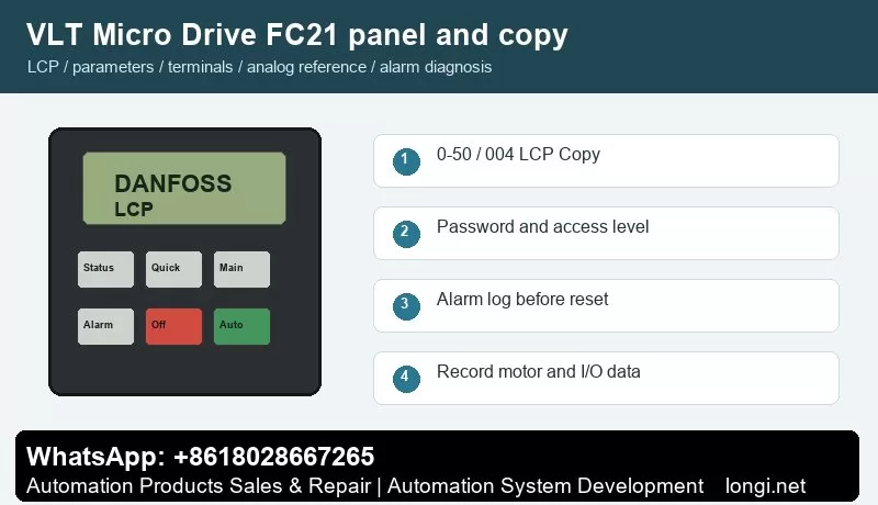
LCP Operation and Copy Functions
The FC21 LCP uses menu navigation, OK, Back, Off/Reset, Local Control and Remote Control. Status is used for actual values, while parameter groups 0, 3, 5, 6, 14, 15 and 16 are important for access, references, inputs, analog scaling, fault action, logs and readout.
Parameter 0-50 LCP Copy supports all parameters to LCP, all parameters from LCP and rating-independent parameters from LCP. Use it before replacing a drive. If the replacement size differs, copy rating-independent data and manually check current, overload, ramp and protection values.
Access Restriction
Parameter 0-60 defines menu password and 0-61 defines access without password. Use read-only access for operators when the machine is commissioned. Keep motor data, reference source, digital input assignment and analog scaling protected.
If a password is unknown, record visible parameters and try to obtain the original commissioning record before initialization. A defaulted FC21 may run, but it may not run the machine correctly.
Terminal Control
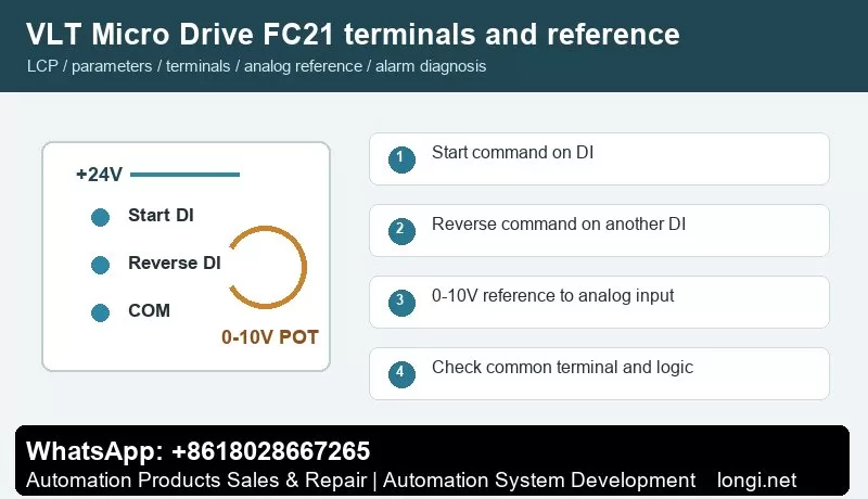
Use terminals 12/13 for control supply and terminal 20 as common. Terminal 18 with 5-10 is normally start. Terminal 27 with 5-12 may be reverse, reset, preset reference or another function. Watch input status on the LCP before connecting the machine load.
For forward/reverse control, assign one input to start and a separate input to reverse. Do not wire both directions in a way that can be active at the same time. If the machine has mechanical one-way limitation, lock reverse in the parameters or remove the external reverse command.
Terminal 53 Potentiometer Setup
Use terminal 50 as +10 V, terminal 53 as analog input and terminal 55 as common. Set 6-10 low voltage, 6-11 high voltage, 6-14 low reference and 6-15 high reference. A typical conveyor may use 0 V = 0 Hz and 10 V = 50 Hz, while a pump may use a minimum reference above zero.
If the speed jumps or drifts, measure voltage directly at 53 and 55. A floating common, damaged potentiometer or shield connected at both ends can create unstable reference even when the parameter values are correct.
Faults Worth Recording
Alarm 2 live zero: terminal 53 signal is below threshold.
Alarm 7/8 overvoltage or undervoltage: check ramp time and mains quality.
Alarm 13 overcurrent: inspect load, motor cable and acceleration.
Alarm 14/44 earth fault: test insulation.
Alarm 47 control voltage fault: remove external 24 V loads and retest.
Alarm 84/86/87/88 LCP communication or copy data issue: reseat the LCP and verify compatibility.
After a parameter change or drive replacement, test the FC21 in four steps. First, keep the motor mechanically unloaded and confirm that Off/Reset works. Second, activate terminal 18 and verify that the LCP shows the input change before the motor accelerates. Third, rotate the external potentiometer from minimum to maximum and record the displayed reference at 0 V, 5 V and 10 V. Fourth, connect the mechanical load and verify current at low, middle and maximum speed.
A healthy FC21 installation should have stable analog reference, predictable direction logic and current below the motor rated value in normal operation. If current rises sharply at low speed, do not increase the current limit first. Check gearbox friction, motor wiring and acceleration time.
Final Service Note
The revised article is intentionally more specific than the previous version. It gives a technician a model-aware procedure instead of a repeated manual summary, and it adds internal context that should make the page more useful for search engines and real users.
Danfoss FC300 FC301 FC302 AutomationDrive Manual Guide: LCP Copy, Encoder-Aware Terminal Control and Fault Diagnosis
AutomationDrive Is Not a Simple Fan Drive
The FC300 family covers FC301 and FC302 AutomationDrive applications. FC301 is often used for high performance speed control, while FC302 extends the range toward servo-like performance, encoder feedback, brake control, positioning and complex fieldbus installations. Because of that, an FC302 service job should not be handled with a generic inverter checklist.
Before editing parameters, identify whether the machine uses open-loop VVC+, encoder feedback, mechanical brake, safe stop, fieldbus command or local terminal command. A copied parameter set that ignores encoder and brake logic may make the motor rotate, but the machine can still lose position, fail to release a brake or trip on tracking errors.
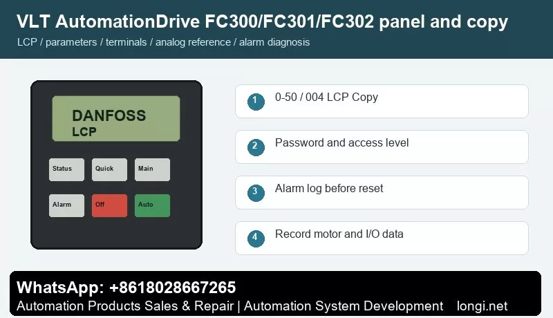
LCP Use: Status, Main Menu and Alarm Log
Use the graphical LCP to view active setup, reference, feedback, motor current, torque, digital input state and alarm log. On FC302, the alarm log is especially important because overcurrent, earth fault, missing phase and tracking-related faults can look similar if only the alarm number is recorded.
When a machine uses a PLC or motion controller, check whether the drive is in local, remote or bus command mode. A service technician may see the terminal input change, but the drive may still be controlled by fieldbus command word.
LCP Copy and Setup Copy
Use parameter 0-50 LCP Copy to move parameter data through the LCP. Stop the drive, upload parameters to the LCP and download only to a compatible drive. If the replacement drive differs in size, voltage class, option cards or software, manually verify motor data, encoder option, brake parameters, safety function and fieldbus mapping.
Use setup copy when the same machine needs multiple operation modes. A conveyor may have a service setup and an automatic setup; a spindle may have one setup for low-speed torque and another for high-speed operation. Document the active setup before changing anything.
Password Access
Use 0-60 Main Menu Password, 0-61 access level and 0-65 Quick Menu Password to protect commissioning data. On FC302, password protection is more important than on simple drives because a wrong encoder, brake or safety parameter can create a real machine hazard.
If the drive is locked, do not initialize first. Save what is visible, read option card type, record motor and encoder plate data, then decide whether initialization is acceptable.
Terminal Forward/Reverse Control
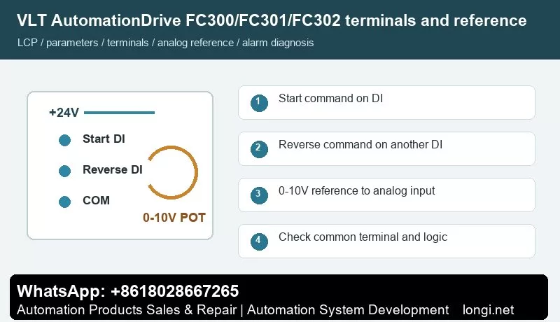
Terminals 12/13 provide +24 V and terminal 20 is common. Terminal 18 with parameter 5-10 is commonly used for start. Terminal 19 with 5-11 can be assigned to reverse. Terminal 27 with 5-12 may be coast stop inverse logic, external interlock or no function. If terminal 27 is still a stop input, it must be held active before the drive can run.
For a PLC-controlled machine, keep start and reverse as separate signals. Do not use direction input as a substitute for stop logic. In hoist, winder, spindle or indexing applications, verify mechanical direction at low speed before allowing automatic operation.
0-10V Reference on Terminal 53
Terminal 50 supplies +10 V, terminal 53 is analog input and terminal 55 is analog common. Set reference resource 1 to analog input 53, then set 6-10, 6-11, 6-14 and 6-15 for low and high scaling. Check the A53 switch before assuming the input is voltage type.
If the FC302 uses encoder feedback, analog reference only defines speed or command value; it does not replace feedback setup. If the motor hunts or overshoots, inspect feedback scaling, motor tuning and controller gains instead of only changing the potentiometer.
Fault Diagnosis for Automation Machines
Alarm 2 live zero: terminal 53/54 signal is missing or below threshold.
Alarm 13 overcurrent: acceleration too aggressive, motor cable issue, mechanical jam or incorrect motor model.
Alarm 14 earth fault / Alarm 16 short circuit: isolate motor and cable before replacing the power module.
Alarm 17 control word timeout / Alarm 34 bus fault: check PLC, fieldbus node address, shield and watchdog time.
Alarm 30/31/32 motor phase missing: inspect output contactor and motor lead continuity.
Brake or tracking warnings: check brake release timing, encoder direction, feedback cable and mechanical load.
Related AutomationDrive Content
For a newer compact automation drive, compare this guide with the FC360 manual guide.
The revised article is intentionally more specific than the previous version. It gives a technician a model-aware procedure instead of a repeated manual summary, and it adds internal context that should make the page more useful for search engines and real users.
Danfoss FC102 HVAC Drive Manual Guide: LCP Backup, Terminal 27 Interlock, 0-10V Reference and Pump Fan Alarm Diagnosis
Why FC102 Needs an HVAC-Specific Reading Method
The FC102 VLT HVAC Drive is normally installed on fans, pumps, cooling towers, air-handling units and building automation panels. It is not enough to know how to start the motor. A service engineer must also understand interlocks, sleep/wake functions, feedback, dry pump detection, broken belt detection and fieldbus handover. For this reason, the FC102 manual should be read as an HVAC commissioning checklist rather than a general inverter manual.
A common mistake is to test only the run signal. In HVAC panels the drive may have a valid start command but still refuse to run because terminal 27 is open, an external interlock is active, the reference is zero, the BMS is holding the command word, or the process protection logic is active.
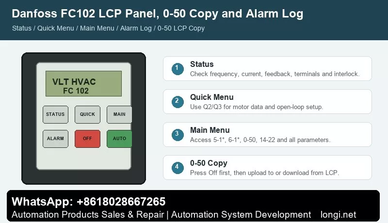
LCP Panel and Alarm Log
The graphical LCP gives quick access to Status, Quick Menu, Main Menu and Alarm Log. Status is used to confirm command source, reference, feedback, output frequency, current and terminal state. Quick Menu is suitable for motor data and basic open-loop setup. Main Menu is needed for terminal functions, analog scaling, interlock behavior and HVAC application functions.
Before resetting an FC102 alarm, open Alarm Log and record the alarm number with the operating values. On a pump trip, current and feedback at the moment of trip are often more important than the alarm text. If a dry pump or no-flow alarm appears, resetting without checking the process can damage the pump.
0-50 LCP Copy for Replacement Drives
Use 0-50 LCP Copy to back up the drive before replacing a control board or complete drive. Press Off first, upload all parameters to the LCP, then download to the replacement drive if the rating and software are compatible. If the replacement is a different size, copy only compatible data and manually verify motor current, pump/fan limits, relay outputs, PID settings, fire mode and fieldbus parameters.
For service records, photograph the motor nameplate, terminal strip, BMS wiring and active setup number. Many FC102 panels use multiple setups for local service and automatic BMS operation, so copying only one setup can leave the machine half restored.
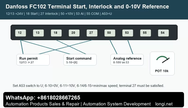
Terminal 18 Start and Terminal 27 External Interlock
A practical open-loop terminal arrangement is: terminal 12 or 13 provides +24 V, terminal 20 is digital common, terminal 18 is set by 5-10 as Start, and terminal 27 is set by 5-12 as coast stop inverse logic or external interlock. If terminal 27 is configured as a stop/interlock input and is not supplied with +24 V, the drive may show coast, external interlock or remote stop even though terminal 18 is active.
Do not bypass terminal 27 permanently without understanding the safety chain. In HVAC cabinets it may include fire damper contact, pressure switch, freeze protection, motor thermal contact, water flow switch or emergency stop relay. For diagnosis, temporarily prove the input with a safe test jumper, then restore the real interlock wiring.
Terminal 53 Potentiometer or BMS Reference
Terminal 50 supplies +10 V, terminal 53 is a voltage analog input, and terminal 55 is analog common. For a service potentiometer, wire 50 to one end, 55 to the other end and the wiper to 53. Set the reference source to analog input 53, set 6-10 to 0 V, 6-11 to 10 V, 6-14 to the low reference and 6-15 to the high reference.
If the same input is used by the BMS, confirm whether it is 0-10 V or 4-20 mA and whether the A53 switch is set correctly. A voltage/current mismatch can create a stable-looking signal that still produces the wrong speed.
HVAC Faults and Correct Actions
Alarm 2 live zero: analog signal is missing or below threshold. Check terminal 53/54 wiring, common terminal and scaling.
Alarm 7 overvoltage: fan or pump inertia is regenerating energy during deceleration. Increase ramp time or check braking arrangement.
Alarm 8 undervoltage / Alarm 4 phase loss: inspect supply, contactor, fuses and building power dips.
Alarm 60 external interlock: trace the terminal 27 safety chain before replacing the drive.
Alarm 92 no flow, 93 dry pump, 94 end of curve, 95 broken belt: treat these as process faults. Check sensor feedback, valve position, belt condition, pump priming and PID settings.
Alarm 30/31/32 motor phase missing: inspect output contactor, motor cable and winding continuity.
For refrigeration and pump applications, compare the FC202 manual guide.
Final Service Note
The revised article is intentionally more specific than the previous version. It gives a technician a model-aware procedure instead of a repeated manual summary, and it adds internal context that should make the page more useful for search engines and real users.
Danfoss FC51 Practical Manual Guide for Service Engineers: LCP Copy, Password Access, Terminal Control and Analog Speed Reference
Why This FC51 Guide Was Rewritten
The FC51 is a small drive, but it is often installed on machines where downtime is expensive: auxiliary conveyors, dosing screws, small pumps, cooling fans, textile units and compact retrofit panels. A generic parameter summary is not enough for this model because the same symptom can come from several different sources. A terminal start failure may be caused by Auto On not being active, by terminal 27 being used as a stop input, by a missing common on terminal 20, or by a reference source that still points to the keypad.
This rewritten guide treats the FC51 manual as a service workflow. It separates local panel operation, parameter copy, password access, external forward/reverse control, 0-10V speed reference and fault code analysis. The goal is to help a technician restore a machine without guessing or replacing the drive unnecessarily.
LCP 11 and LCP 12: What to Check Before Editing Parameters
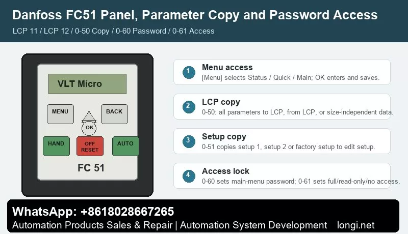
The FC51 normally uses LCP 11 without a potentiometer or LCP 12 with a built-in potentiometer. Both panels give access to Status Menu, Quick Menu and Main Menu. Status Menu is the first place to look because it shows whether the drive is actually receiving a run command and whether the reference value is zero. Quick Menu is useful for motor nameplate data and basic ramps. Main Menu is required for digital input, analog input, password and copy parameters.
Hand On, Off/Reset and Auto On must be understood before terminal control is tested. Hand On runs the drive from the keypad. Off/Reset stops and resets. Auto On allows terminal or serial control. If a technician tries to start from terminal 18 while the drive is left in local mode, the wiring may look wrong even when it is correct.
On LCP 12, the panel potentiometer is not the same as an external potentiometer wired to terminal 53. During troubleshooting, write down whether speed reference is coming from keypad, LCP potentiometer, terminal 53, preset reference or communication.
Parameter Copy: 0-50 LCP Copy and 0-51 Setup Copy
Parameter 0-50 LCP Copy is used to move settings through the removable LCP. Use All to LCP on the source drive, then All from LCP on a target drive with the same rating and hardware. If the target drive is a different size, use the size-independent option and then manually confirm motor current, overload protection, current limit, braking and analog scaling.
Parameter 0-51 Setup Copy is different. It copies setup data inside the same drive. This is useful when the machine has two operating recipes, for example manual jog and automatic production. A good practice is to finish setup 1, copy it to setup 2, and change only the reference source or ramp values that are different.
Do not copy while the machine is running. Stop the drive, wait until the motor has coasted down, and keep a written record of motor data, terminal assignments, reference source and fault action before replacing hardware.
Password Access and Unlocking Without Losing the Machine Setup
Use 0-60 Main Menu Password and 0-61 Access to Main Menu without Password to control who can change parameters. Use 0-65 Quick Menu Password when operators should view status but not change commissioning data. In a service panel, operators normally need status, start/stop and reset; they do not need to edit motor current, terminal logic or analog scaling.
If the FC51 is locked, do not initialize it immediately. First ask for the commissioning password, check the machine documentation, photograph visible parameter screens and save the LCP copy if possible. Initialization is the last step because it can erase the real application logic.
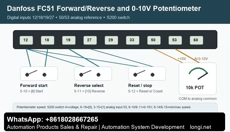
External Forward/Reverse Wiring
The common terminal logic is simple but easy to miswire. Terminal 12/13 provides the control supply, terminal 20 is the common terminal, terminal 18 is commonly used for start, terminal 27 is often used for coast stop or another digital function, and terminal 29 or 33 may be assigned to jog, reverse or preset reference depending on the application.
For a two-wire forward/reverse selector, use one input as the run command and a second input as reverse direction. For a three-wire station, separate start, stop and direction. Always test terminal state on the LCP before connecting the motor to the machine. If the drive shows a run command but output frequency remains zero, check reference source and minimum reference before changing the power circuit.
External 0-10V Potentiometer Reference
For a standard external potentiometer, wire one end to terminal 50 (+10 V), the other end to terminal 55 (analog common), and the wiper to terminal 53. Then set the reference source to analog input 53. Low voltage should correspond to the minimum reference and high voltage should correspond to the maximum speed required by the machine.
If the drive reports live zero, the analog signal is below the configured threshold. Check whether terminal 53 is set as voltage input, whether the common wire is actually connected to 55, whether shield grounding is creating noise, and whether the potentiometer value is appropriate. A stable 0-10 V measurement at the terminal is more useful than changing random parameters.
Fault Codes That Matter Most on FC51
Live zero / wire break: terminal 53 is below the expected signal. Measure voltage between 53 and 55.
Overvoltage: deceleration is too short, load inertia is high, or braking is not working. Increase deceleration time before replacing hardware.
Undervoltage or phase loss: check supply voltage, input contactor and fuses.
Overcurrent or short circuit: disconnect the motor and test insulation between U/V/W and earth.
Motor overload: verify motor nameplate data and cooling condition.
LCP copy failure: check LCP seating, drive rating, software compatibility and whether the motor is stopped.
The revised article is intentionally more specific than the previous version. It gives a technician a model-aware procedure instead of a repeated manual summary, and it adds internal context that should make the page more useful for search engines and real users.
The Danfoss VLT2900 is an older but still widely used compact AC drive. It appears in fans, pumps, conveyors, textile machines, packaging equipment, dyeing machines and many other small-power industrial systems. Its parameter structure is close to the VLT2800 family, so many operation, wiring and fault-diagnosis methods are shared. For service work, the key is not to read the whole manual line by line, but to quickly master the practical workflow: use the panel correctly, copy parameters, unlock data changes, wire forward/reverse terminals, use a 0-10V potentiometer as a speed reference, and interpret Err.xx fault codes.
This guide summarizes the user manual from a repair and commissioning perspective. Parameter numbers are based on the VLT2900/VLT2800 manual structure. Before commissioning, always verify the nameplate, motor data, control logic and machine safety circuit.
Control Panel and Menu Access
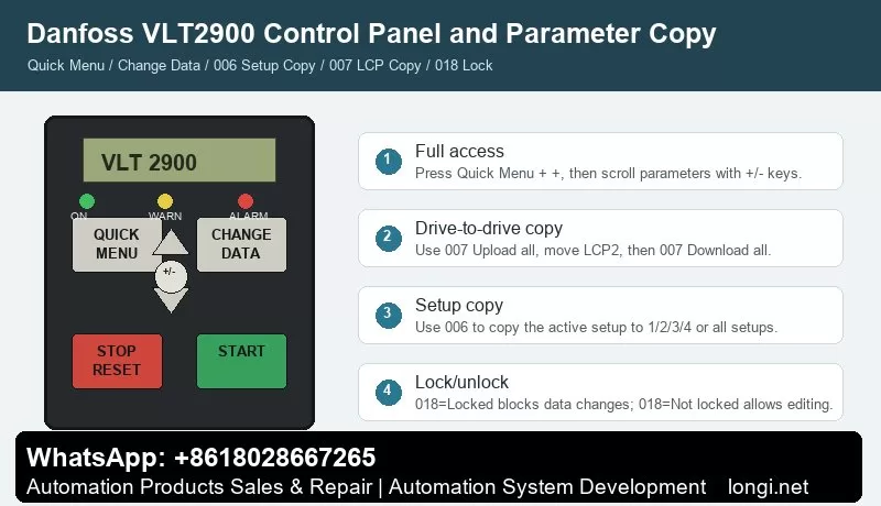
The basic VLT2900 panel normally includes QUICK MENU, CHANGE DATA, +, -, STOP/RESET and START. With an LCP2 control panel, extra keys such as OK, arrow keys, HAND, OFF, AUTO, FWD/REV and JOG may be available. The indicator LEDs show ON, WARNING and ALARM. A warning means an abnormal condition is present but the drive may continue to run; an alarm usually requires fault correction and reset.
QUICK MENU opens the quick commissioning menu. It normally contains motor nameplate data, minimum and maximum reference, ramp times and basic operation settings. Use + / – to scroll, press CHANGE DATA to edit, change the value with + / –, and confirm with CHANGE DATA or OK. Parameter values are stored automatically and remain after power loss.
If only a limited number of parameters are visible, the drive is usually not "encrypted". It is often still in Quick Menu mode. To access all parameters, press QUICK MENU and + at the same time to enter the full menu mode, then scroll to the required parameter.
STOP/RESET stops the drive command and resets alarms, but it is not a safety isolator. For short circuit, earth fault, overtemperature or power-stage faults, disconnect mains power and wait for the DC bus to discharge before touching the terminals.
Parameter Copying: 006 and 007 Are Different
Two parameters are commonly confused: 006 Setup copying and 007 LCP copy.
Parameter 006 Setup copying copies the active setup inside the same drive. It can copy the active setup to Setup 1, 2, 3, 4 or all setups. It is useful when several machine recipes are needed. Stop the motor before copying because changes copied to the active setup can affect drive operation immediately.
Parameter 007 LCP copy is used with the LCP2 panel to move parameters from one drive to another. The normal workflow is:
Install the LCP2 on the source drive.
Enter 007 LCP copy.
Select Upload all parameters.
Move the LCP2 to the target drive.
Select Download all parameters.
If the target drive has a different power size, use Download size-independent parameters instead.
Do not blindly download all parameters between drives of different voltage class, power size or hardware version. After copying, verify motor parameters 102-106, references 204/205, ramps 207/208, terminal parameters in group 300 and communication parameters in group 500.
Locking, Unlocking and "Password" Misunderstanding
VLT2900 does not normally use a password-style lock for routine parameter access. Two conditions are often mistaken for encryption.
The first is limited menu access. Press QUICK MENU + + to enter full menu mode.
The second is the real data-change lock: 018 Data change lock. Set it to Locked [1] to block parameter changes. Set it back to Not locked [0] to allow editing. If the drive shows Warning 99 Locked, check parameter 018. If editing is still impossible, stop the motor, remove active start signals and confirm whether an LCP2 panel is required for editing.
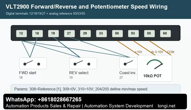
External Forward/Reverse Control by Terminals
The manual gives practical examples for digital input control. Typical factory assignments include 302 Digital input terminal 18 = Start, 303 terminal 19 = Reversing, and 304 terminal 27 = Reset and coast inverse.
A practical forward/reverse wiring scheme is:
Terminal 12 provides the digital control supply.
Terminal 18 receives the forward start signal. Wire a switch from 12 to 18 and set 302=Start [7].
Terminal 19 receives the reverse selection signal. Wire a switch from 12 to 19 and set 303=Reversing [10].
Terminal 27 is commonly used for coast stop inverse or reset/coast inverse. It normally needs a valid logic signal through the safety circuit. Set 304=Coasting stop inverted [2] or according to the actual machine requirement.
Also check parameter 200 Output frequency range/direction. If the drive is set for clockwise operation only, the reverse input will not produce reverse rotation. For real forward/reverse operation, select a direction range that allows both directions.
Test first at low frequency and without load. Confirm the output frequency, motor direction and mechanical safety before running the machine under load.
Potentiometer Speed Reference: Terminals 50, 53 and 55
The manual example for Potentiometer reference uses a voltage reference through terminal 53. The required settings are 308 Analog input = Reference [1], 309 Terminal 53 min scaling = 0V, and 310 Terminal 53 max scaling = 10V.
Typical 10k ohm potentiometer wiring:
Terminal 50: +10V supply to one end of the potentiometer.
Terminal 55: analog common to the other end.
Terminal 53: analog voltage input to the wiper.
Recommended parameters:
308 Terminal 53 analog input = Reference [1].
309 Terminal 53 min scaling = 0.0V.
310 Terminal 53 max scaling = 10.0V.
204 Minimum reference defines the minimum speed.
205 Maximum reference defines the maximum speed.
207/208 Ramp-up and ramp-down times should be set to match the mechanical inertia.
If the potentiometer does not work, measure the voltage on terminal 53 first. Then check parameter 308 and verify that the drive is in remote control and not being overridden by local reference, preset speed or serial communication. If Err.02 Live zero error appears, terminal 53 or 60 is below 50% of the configured minimum scaling value.
Fault Codes and Troubleshooting
VLT2900 alarms are displayed as Err.xx. A warning stays active while the condition exists. An alarm flashes until reset. A trip-locked fault requires power removal, fault correction and restart before reset.
Err.02 Live zero error: terminal 53 or 60 signal is below the expected minimum. Check potentiometer wiring, analog common, terminal 53 voltage, parameter 309/315 and sensor supply.
Err.05 Voltage warning high / Err.07 Overvoltage: usually caused by too short deceleration, high inertia, brake resistor faults or high mains voltage. Increase ramp-down time and inspect the brake circuit.
Err.06 Voltage warning low / Err.08 Undervoltage: check mains supply, contactor drop-out, rectifier, precharge circuit and DC bus capacitors.
Err.09 Inverter overload: check mechanical overload, drive sizing, acceleration time and cooling.
Err.10 Motor overloaded: verify motor parameters 102-106, load condition and cooling at low speed.
Err.11 Motor thermistor: check the PTC thermistor and wiring between a digital input and terminal 50, and verify parameter 128.
Err.12 Current limit: output current exceeds parameter 221. Check acceleration time, load, torque demand and mechanical friction.
Err.13 Overcurrent: check motor shaft blockage, motor cable, output short circuit and IGBT module. Do not keep resetting repeatedly.
Err.14 Earth fault: inspect motor insulation, motor cable, water ingress and shield contact. Disconnect power and test insulation.
Err.15 Switch mode fault: internal auxiliary power supply fault, usually a board-level repair issue.
Err.16 Short-circuit: check U/V/W phase-to-phase short circuit, motor winding and power module.
Err.17 Serial communication timeout: check group 500 communication parameters, address, baud rate, protocol and cable shielding.
Err.18 HPFB bus timeout / Err.34 HPFB communication fault: fieldbus or PROFIBUS option communication problem.
Err.33 Out of frequency range: check parameter 200, frequency limits and direction restrictions.
Err.35 Inrush fault: inspect precharge resistor, relay, rectifier and DC bus capacitors.
Err.36 Overtemperature: check fan, heatsink dust, ambient temperature, motor cable length, carrier frequency and mains voltage.
Err.37-45 Internal fault: internal control card, EEPROM, RAM, calibration, power card, software or I/O fault. Record the exact code before repair.
Err.50-56 AMT faults: automatic motor adaptation failed. Check motor nameplate data, output cable, motor phase connection and load condition.
Warning 99 Locked: parameter changes are locked. Check 018 Data change lock.
Practical Commissioning Sequence
Start by checking power wiring, motor insulation, earthing and control terminals. Enter full menu access, set motor data 102-106, configure terminal 18/19/27 logic, set reference limits 204/205, set ramps 207/208, configure terminal 53 with 308/309/310, then test the motor at low speed without load. After successful testing, back up parameters. Use 007 LCP copy for drive-to-drive copying and 006 Setup copying for internal setup duplication.
Conclusion
The VLT2900 manual becomes much easier to use when its main structure is clear: QUICK MENU is for fast commissioning, QUICK MENU + + gives full parameter access, CHANGE DATA edits values, STOP/RESET stops and resets, 006 copies internal setups, 007 copies parameters through LCP2, 018 locks or unlocks data changes, 302/303/304 define terminal 18/19/27 control, 308/309/310 define the 0-10V potentiometer reference, and Err.xx codes point the troubleshooting direction.
Used this way, the manual is not just a parameter list. It becomes a practical diagnostic map for commissioning, service and repair of Danfoss VLT2900 drives.
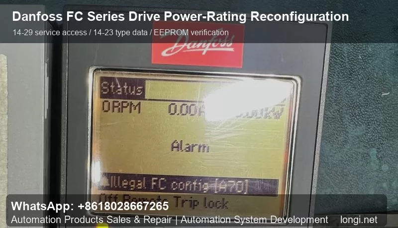
Danfoss VLT FC series drives, including FC102, FC202 and FC302, are frequently seen in industrial repair work. These drives rely on a consistent relationship between the control board, LCP keypad, power board, rectifier/inverter section and the type data stored in memory. After replacing a control board or using a spare board from another drive of the same platform, the drive may power up but report configuration alarms, illegal FC configuration, A70-related messages, or a mismatch between the displayed power rating and the actual power hardware.
The “power-rating change” discussed here is not a method to turn a small drive into a larger drive by software. It is a service operation used to make the stored type data match the real hardware. The repair engineer must verify the nameplate, voltage class, power board, IGBT module, rectifier, DC bus capacitors, heatsink and fan structure before changing the parameters. If the rating is written incorrectly, the drive may appear normal at no load but fail under load due to current, thermal or protection mismatch.
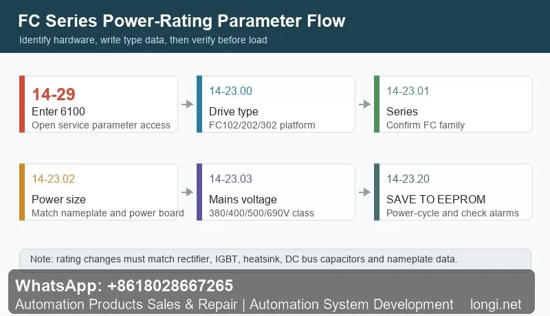
The key service path is usually entered from the LCP. After the keypad displays normally, enter the main menu, find parameter 14-29, press OK, input service code 6100, and confirm. Then enter the 14-23 parameter group. The typical sequence is to set the drive type in 14-23.00, confirm the FC series in 14-23.01, select the correct power size in 14-23.02, select the correct mains voltage class in 14-23.03, and finally use 14-23.20 SAVE TO EEPROM to store the type data permanently.
Saving to EEPROM is important because these parameters are not ordinary application settings. They are involved in drive identification, rated current limits, voltage class recognition, fan behavior, thermal protection and internal protection thresholds. If the EEPROM save step is skipped, the drive may return to the previous configuration after power cycling. For a proper repair, the drive should be powered off, restarted, checked for alarms, and the 14-23 parameters should be reviewed again.
Before any loaded test, start with a no-load power-up. Check DC bus behavior, fan operation, keypad status, alarm history and temperature feedback. Then run the motor without load and verify output current, output voltage, frequency response and motor direction. After that, apply load gradually. If the current reading is obviously too high or too low, inspect the current sensor, power board type, sampling circuit and selected rating. On FC302 applications, an incorrect current scale can also affect vector control performance.
Common mistakes include selecting a higher rating than the actual hardware, ignoring the voltage class, replacing boards only by appearance, clearing alarms without reading the alarm history, and failing to document the original parameters. A reliable repair should include photos of the nameplate, board codes and original settings before modification.
In summary, Danfoss FC series power-rating reconfiguration is a practical repair procedure after board replacement or type-data loss. The core steps are 14-29 with code 6100, type settings in 14-23.00 to 14-23.03, and EEPROM saving through 14-23.20. The most important principle is simple: the parameter data must follow the hardware, not the other way around. When hardware identification, parameter writing, EEPROM storage, power-cycle verification and load testing are all completed, this procedure can restore a repaired FC series drive to a stable and serviceable state.
In new energy vehicle maintenance, complaints such as “the air conditioner is not cooling,” “the compressor makes no sound,” or “the diagnostic tester shows an A/C-related fault” are very common. In particular, when servicing BYD electric vehicles equipped with high-voltage electric air-conditioning compressors, many technicians still use the diagnostic habits developed from conventional gasoline vehicles: once the A/C does not work, they immediately suspect the compressor and may even recommend replacing the entire compressor assembly.
This approach is risky and often incorrect.
A new energy vehicle A/C compressor is not a conventional belt-driven mechanical compressor. It is a high-voltage electric device supplied by the traction battery, usually integrating an electric motor, inverter drive circuit, control electronics, protection circuits, and communication functions. Whether the compressor can run does not depend only on the compressor itself. It also depends on high-voltage system status, vehicle control permissions, battery management system conditions, refrigerant pressure, temperature sensors, A/C controller commands, CAN communication, and high-voltage interlock circuits.
Therefore, when diagnosing a BYD electric vehicle with suspected A/C compressor failure, the correct principle is:
Confirm whether the compressor has all required operating conditions before concluding that the compressor itself is defective.
A compressor should never be replaced simply because the A/C is not cooling, the compressor appears not to run, or a diagnostic screen shows an abnormal condition.
This article explains the structure, working logic, fault diagnosis process, key data parameters, and common misdiagnoses associated with BYD high-voltage electric A/C compressors. It is intended as a practical technical reference for electric vehicle service technicians, automotive repair workshops, and maintenance professionals.
1. Identifying the Component: This Is Not a Conventional Compressor
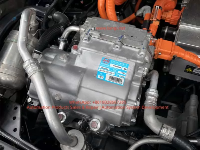
The nameplate on the component provides several important details:
Manufacturer: BYD Auto Industry Co., Ltd.
Description: Electric Compressor Assembly
Refrigerant: R134a
Rated operating voltage: approximately 408.8 V
Compressor model: HDE-8103020D
Compressor assembly identification code: ACE66D or similar, depending on the exact label marking
The most important markings are “Electric Compressor Assembly” and “408.8 V.”
These markings confirm that the component is part of the vehicle high-voltage thermal management system. Unlike a traditional engine-driven compressor, it is powered directly by the traction battery through the high-voltage system. The internal inverter converts high-voltage DC power into three-phase AC power to drive the compressor motor.
A high-voltage electric A/C compressor can generally be considered a combination of the following sections:
Compressor mechanical body
Three-phase permanent magnet motor
Internal inverter drive module
Electronic control board
Rotor position or speed detection circuit
High-voltage DC input section
Low-voltage communication and control connector
Internal temperature protection circuit
Insulation monitoring-related structure
Refrigerant compression and lubrication system
For this reason, the traditional gasoline vehicle inspection method of “checking whether the 12 V compressor clutch engages” does not apply to electric vehicles.
Most high-voltage electric compressors do not use conventional electromagnetic clutches. Their operation depends on whether the vehicle control system issues a speed command, whether high-voltage power is available, whether safety conditions are satisfied, and whether the compressor itself has internal electrical or mechanical faults.
2. Fundamental Differences Between EV and Conventional Vehicle A/C Systems
The operating logic of a conventional gasoline vehicle A/C system is relatively simple:
The logic of an electric vehicle A/C system is much more complex:
Traction battery high-voltage system powers on → BMS confirms battery status is acceptable → High-voltage contactors close → VCU confirms the vehicle is in an allowed operating condition → A/C controller receives a cooling request → System checks cabin temperature, ambient temperature, evaporator temperature, refrigerant pressure, and other conditions → A target compressor speed command is sent through CAN communication → Compressor verifies high-voltage supply, communication status, and internal conditions → Internal inverter drives the electric motor → Compressor circulates refrigerant and produces cooling.
This process shows that a compressor may fail to operate for many reasons other than compressor damage.
The main categories include:
No A/C request or no compressor command
High-voltage system not powered up correctly
Compressor communication failure
Refrigerant system conditions not satisfied
Internal compressor electronic or mechanical fault
No cooling does not automatically mean the compressor has failed. Compressor not running does not automatically mean the compressor assembly is defective.
3. Common Incorrect Judgments During Diagnosis
Several mistakes are frequently made when diagnosing high-voltage electric compressor faults.
3.1 No Audible Compressor Noise Means the Compressor Is Bad
This is not reliable.
Electric compressors can be very quiet, especially at low speed. In a noisy workshop environment, with cooling fans operating or with underbody insulation installed, it may be difficult to hear compressor operation from outside the vehicle.
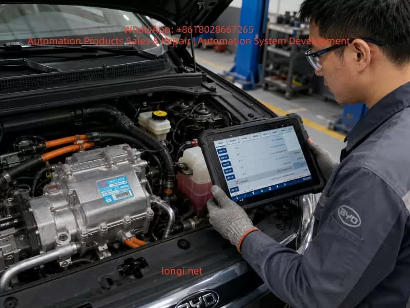
The correct approach is to use a diagnostic tool and inspect live data such as:
A/C request status
Compressor enable status
Compressor target speed
Compressor actual speed
Compressor operating status
Compressor fault level
High-voltage bus voltage
Refrigerant pressure
Evaporator temperature
Compressor current or power consumption
If the target speed is commanded but actual speed remains zero, then the technician can begin to suspect the compressor, high-voltage supply, or communication circuit.
3.2 A/C Not Cooling Means Refrigerant Must Be Added or Compressor Must Be Replaced
This is another common mistake.
In an electric vehicle, low refrigerant charge, excessive refrigerant charge, refrigerant leakage, pressure sensor failure, electronic expansion valve malfunction, or poor condenser cooling can all prevent the compressor from operating.
For example:
If refrigerant pressure is too low, the system may assume leakage and disable the compressor.
If refrigerant pressure is too high, the system may enter overpressure protection.
If the evaporator temperature is too low, the controller may stop the compressor to prevent icing.
If the condenser fan is not working, high-side pressure may rise and trigger shutdown.
If the pressure sensor signal is unreliable, the controller may refuse to enable the compressor.
Therefore, adding refrigerant or replacing the compressor without checking pressure data and fault codes is not a professional diagnostic method.
3.3 Measuring High Voltage Directly at the Compressor Without Proper Procedure
This is dangerous.
The compressor label indicates an operating voltage around 408.8 V. The high-voltage input circuit may therefore carry several hundred volts DC. Improper disconnection of high-voltage connectors, careless measurement with an unsuitable multimeter, or failure to follow the correct high-voltage isolation procedure can result in electric shock, arcing, short circuits, or damage to the vehicle control system.
Before servicing a high-voltage compressor, technicians must follow the manufacturer-approved high-voltage shutdown procedure. This generally includes isolating high-voltage power, waiting for capacitor discharge, confirming absence of voltage, and using proper insulated safety equipment.
3.4 Diagnostic Tool Shows “Normal,” So the Compressor Must Be Good
This conclusion is also unreliable.
A diagnostic tool showing “normal” may only indicate that a control module has not reported a specific active fault or that communication with the module is currently available.
It does not necessarily prove that:
The compressor mechanical section is healthy.
The internal inverter is functioning correctly under load.
The compressor can run normally at commanded speed.
Refrigeration performance is normal.
The refrigerant circuit is operating correctly.
For example, a compressor may pass its static self-check but fail when it receives a high-speed command due to overcurrent, mechanical seizure, overheating, insulation issues, or internal inverter faults.
For this reason, fault codes, live data, dynamic operation, refrigerant pressure changes, and actual cooling performance must all be evaluated together.
4. Required Operating Conditions for a High-Voltage Electric Compressor
The most effective way to diagnose whether a high-voltage compressor should operate is not immediate disassembly. Instead, the technician should establish whether all operating conditions are present.
A typical high-voltage electric compressor requires the following conditions.
4.1 Vehicle High-Voltage System Must Be Active
The vehicle must successfully enter READY mode or complete its high-voltage power-up process.
If the traction battery contactors are not closed and the high-voltage bus is not established, the compressor cannot receive the required DC voltage and cannot operate.
Relevant checks include:
Can the vehicle enter READY mode normally?
Is there any traction system warning light?
Is there any insulation fault in the high-voltage system?
Are the high-voltage contactors closing correctly?
Does the BMS report any fault preventing high-voltage activation?
Is the service disconnect correctly installed?
Is the high-voltage interlock circuit intact?
4.2 The A/C Controller Must Issue a Cooling Request
Pressing the A/C button does not always mean the compressor must start immediately.
The controller may evaluate:
Ambient temperature
Cabin temperature
Requested set temperature
Evaporator temperature
Defrost requirements
Battery thermal management demand
Energy-saving strategy
Battery state of charge
Battery temperature
Vehicle operating mode
Communication status between A/C-related control units
For example, in cold ambient conditions, the compressor may not start immediately even when the A/C button is pressed. On the other hand, the compressor may run for battery thermal management even if the cabin cooling demand is low.
4.3 High-Voltage Supply Must Be Normal
The compressor requires stable high-voltage DC input.
The following items should be checked:
High-voltage bus voltage
Compressor high-voltage fuse
High-voltage connector condition
High-voltage cable damage
High-voltage power distribution output
High-voltage interlock circuit
Connector locking condition
Terminal corrosion, overheating, or looseness
It is important to understand that a high-voltage supply fault does not always mean complete loss of voltage. A loose connector, partially burnt terminal, or damaged cable may appear acceptable under no-load conditions. However, when compressor current rises during startup, voltage may collapse and trigger compressor protection.
4.4 CAN Communication Must Be Normal
In many electric vehicles, the compressor receives operating commands through CAN communication.
Relevant modules may include:
Vehicle Control Unit, VCU
Battery Management System, BMS
Air-conditioning controller
Thermal management controller
Battery thermal management controller
Electric compressor controller
DC-DC converter
PTC heater controller
Gateway module
If compressor CAN communication is abnormal, the following symptoms may occur:
A/C panel operates normally, but compressor does not start.
The display shows A/C enabled, but no cold air is produced.
Compressor communication fault codes are present.
Compressor target speed remains zero.
Diagnostic tester cannot access compressor live data.
Other high-voltage systems appear normal while thermal management functions fail.
4.5 Refrigerant System Pressure Must Be Within Normal Range
An electric compressor is not allowed to run under every condition simply because high voltage is present.
Many EVs use refrigerant pressure data to determine whether compressor operation is safe. If refrigerant pressure is too low, too high, unstable, or implausible, the controller may limit or stop compressor operation.
Typical issues include:
Refrigerant leakage causing low pressure
Incorrect refrigerant charge after repair
Condenser blockage or poor airflow
Electronic expansion valve sticking
Receiver-drier blockage
Pressure sensor drift
Damaged or crushed refrigerant pipes
Air or moisture contamination in the system
Incorrect compressor oil type
Electric compressors require refrigeration oil with suitable electrical insulation properties. Using incorrect oil, mixing conventional compressor oil, or contaminating the system with unsuitable service equipment can reduce insulation resistance and potentially cause electrical or internal compressor damage.
4.6 Compressor Internal Condition Must Be Normal
Only after all external operating conditions have been confirmed should the compressor itself become the primary suspect.
Internal compressor faults may include:
IGBT or MOSFET failure
DC bus capacitor failure
Drive board failure
Control chip failure
Motor winding short circuit, open circuit, or turn-to-turn fault
Rotor seizure
Scroll mechanism damage
Bearing damage
Internal temperature sensor fault
Rotor position sensor fault
Seal failure causing refrigerant or oil contamination
Insulation resistance failure
Water ingress or corrosion in electronic circuits
These faults are genuine compressor assembly faults.
5. Using Diagnostic Live Data to Determine Compressor Failure
The most valuable step in electric compressor diagnosis is reading complete live data before removing parts.
The following parameters should be checked whenever available:
Parameter
Normal Diagnostic Direction
Possible Fault Direction
A/C request status
Request active
A/C panel, controller, communication issue
Compressor enable status
Allowed to run
Protection condition or system restriction
Compressor target speed
Target RPM present
Controller not commanding compressor
Compressor actual speed
Should follow target RPM
Compressor, power supply, communication, protection
Compressor status
Normal operation
Internal fault or disabled status
High-voltage bus voltage
Within normal HV range
Battery, contactor, fuse, wiring issue
Compressor current
Should change after startup
No startup, internal fault, supply problem
Refrigerant pressure
Within operating range
Refrigerant, sensor, fan, blockage issue
Evaporator temperature
Should decrease during cooling
Cooling performance or sensor issue
Condenser fan status
Should operate when required
Fan, relay, controller issue
Battery temperature
Within acceptable range
Thermal management or power limitation
Compressor fault code
No active compressor fault
Use code to guide diagnosis
The most important diagnostic logic is described below.
Condition A: Compressor Target Speed Is Zero
This means the vehicle is not requesting compressor operation.
In this case, do not suspect the compressor first. Check:
Is the A/C request active?
Does the A/C controller permit cooling?
Is ambient temperature appropriate?
Is cabin temperature above the set value?
Is refrigerant pressure normal?
Is evaporator temperature too low?
Is the BMS limiting power?
Is there a high-voltage or thermal management fault?
Is CAN communication normal?
Condition B: Compressor Target Speed Exists but Actual Speed Remains Zero
This condition is highly important.
It means the vehicle has commanded the compressor to operate, but the compressor has not successfully started.
The technician should focus on:
Compressor high-voltage supply
High-voltage fuse
High-voltage connector
High-voltage interlock circuit
Compressor CAN communication
Compressor internal fault codes
Compressor temperature
Compressor mechanical seizure
Compressor insulation status
If high voltage, CAN communication, control command, and refrigerant conditions are all normal, but the compressor still cannot establish actual speed, the probability of internal compressor failure becomes high.
Condition C: Compressor Speed Exists but Cooling Performance Is Poor
This situation does not automatically require compressor replacement.
It indicates that the compressor may be running, but the refrigeration system is not performing correctly.
Focus on:
Refrigerant charge level
Leakage
Condenser cooling efficiency
Cooling fan operation
Expansion valve condition
Refrigerant line blockage
Evaporator icing
Pressure sensor reliability
Reduced compressor displacement or compression efficiency
Condition D: Compressor Starts Briefly and Then Stops
This is a common symptom and is not always caused by compressor damage.
Possible causes include:
Excessive refrigerant pressure
Condenser fan failure
Refrigerant overcharge
Compressor internal overheating
High-voltage bus voltage fluctuation
High-voltage terminal contact resistance
Compressor overcurrent
Internal inverter protection
Insulation monitoring fault
Intermittent CAN communication loss
Battery system power limitation
The best approach is to record freeze-frame data and observe which parameter becomes abnormal immediately before shutdown.
6. Common BYD High-Voltage Compressor Fault Types
6.1 High-Voltage Fuse or Connector Fault
The compressor normally receives power through the high-voltage power distribution system. If the fuse is open, the connector is loose, terminals are burnt, or the cable is damaged, the compressor may not start.
Typical symptoms include:
Vehicle can enter READY mode.
Other high-voltage systems may work normally.
A/C compressor has no response.
High-voltage supply-related fault code may be present.
Compressor target speed exists, but actual speed remains zero.
Inspect high-voltage connectors carefully for:
Burn marks
Darkened terminals
Melted plastic
Loose terminals
Damaged seals
Connector not fully locked
Moisture ingress
Cable insulation wear
6.2 High-Voltage Interlock Circuit Fault
The high-voltage interlock circuit confirms that high-voltage components, service disconnects, and connectors are correctly connected.
For example, if the compressor high-voltage connector is not fully locked, the service disconnect is not installed correctly, or another high-voltage connector is loose, the vehicle may disable some or all high-voltage functions.
A high-voltage interlock fault may not always appear as a direct “compressor fault.” It may present as:
Vehicle unable to enter READY mode
High-voltage system not powering on
Reduced power mode
A/C not functioning
High-voltage warning lamp illuminated
Several high-voltage components reporting faults simultaneously
Therefore, technicians should inspect the complete high-voltage system rather than focusing only on the compressor.
6.3 Refrigerant Leakage or Pressure Sensor Inaccuracy
Sometimes the compressor does not start because the A/C controller considers refrigerant pressure abnormal.
Possible causes include:
Refrigerant leakage causing low pressure
Condenser or pipe leakage after impact
Incorrect vacuuming or charging procedure after repair
Loose pressure sensor connector
Pressure sensor internal drift
Refrigerant circuit blockage
Poor condenser heat dissipation causing high pressure
In these cases, the compressor may be completely healthy but will not receive permission to run.
6.4 Condenser Fan Failure
A condenser fan failure can cause poor heat dissipation and excessive high-side pressure.
Typical symptoms include:
Cold air is available initially.
Cooling becomes weak after several minutes.
Cooling is better while driving but poor when stationary.
Compressor cycles on and off repeatedly.
Refrigerant high-side pressure rises quickly.
Cooling fan does not run or runs at insufficient speed.
If the fan fault is ignored, repeated high-pressure operation can cause frequent compressor protection events and may eventually contribute to compressor overheating.
6.5 Internal Inverter Drive Module Failure
A high-voltage electric compressor contains its own inverter drive circuit. When internal power components fail, possible symptoms include:
Compressor cannot start.
Compressor faults immediately during startup.
High-voltage fuse opens.
Internal drive fault code is stored.
Overcurrent, short-circuit, or phase-current faults are reported.
Motor winding-related faults are reported.
Compressor starts briefly and shuts down.
These faults often require compressor replacement or specialist repair by a workshop with capability to test high-voltage electric drive components.
6.6 Mechanical Seizure or Internal Wear
Many electric compressors use scroll compression mechanisms. Long-term operation, contaminated refrigerant oil, insufficient refrigerant, foreign material, or poor lubrication may cause internal mechanical damage.
Typical symptoms include:
Excessive startup current
Abnormal metallic friction noise
Significant loss of cooling capacity
Abnormally high compressor temperature
Metal particles in refrigerant oil
Repeated compressor protection
Compressor speed feedback present but poor cooling performance
If internal mechanical damage is confirmed, replacing only the compressor may not be sufficient. The entire refrigerant circuit must be checked and cleaned. Otherwise, metal particles or contamination can damage the replacement compressor.
7. Standard Diagnostic Procedure for Confirming Compressor Failure
The following procedure can be applied to most high-voltage electric vehicle A/C compressor faults.
Step 1: Confirm the Actual Symptom
Clarify the customer complaint:
No cooling at all
Weak cooling
Intermittent cooling
Cooling while driving but not when stationary
A/C-related warning message
Vehicle unable to enter READY mode
High-voltage fault appears when A/C is switched on
Compressor starts and stops immediately
Abnormal compressor noise
Refrigerant or oil leakage around the compressor
Different symptoms require different diagnostic priorities.
Step 2: Scan All Vehicle Fault Codes
Do not scan only the A/C system.
At minimum, inspect fault codes from:
VCU
BMS
A/C controller
Thermal management controller
Compressor
High-voltage power distribution system
Gateway
DC-DC converter
Insulation monitoring system
Motor controller
Pay particular attention to:
High-voltage interlock faults
High-voltage activation faults
Compressor communication faults
Compressor internal faults
Pressure sensor faults
Temperature sensor faults
High-voltage insulation faults
CAN communication faults
Refrigerant pressure faults
Condenser fan faults
Fault codes must be evaluated together with freeze-frame data, live data, current fault status, and historical records. Clearing a fault code does not confirm that the root cause has been repaired.
Step 3: Confirm High-Voltage System Readiness
Verify:
Vehicle can enter READY mode.
Traction battery state of charge is sufficient.
High-voltage contactors close normally.
High-voltage bus voltage is normal.
No insulation fault exists.
No high-voltage interlock fault exists.
Service disconnect is correctly installed.
High-voltage wiring and connectors are intact.
If the vehicle cannot establish high-voltage power, diagnose the high-voltage system first instead of beginning with the compressor.
Step 4: Check Compressor Request, Target Speed, and Actual Speed
This is the key diagnostic step.
The logic can be summarized as follows:
No A/C request → Check control conditions.
A/C request present, but compressor not enabled → Check protection conditions, pressure, temperature, high voltage, and communication.
Target speed present, actual speed zero → Check compressor power supply, communication, and internal fault status.
Target speed and actual speed both present → Check refrigerant circulation, condenser cooling, expansion valve, and cooling efficiency.
Step 5: Check the Refrigerant System
Use suitable R134a A/C service equipment to inspect:
Static low-side and high-side pressure
Dynamic low-side and high-side pressure
Refrigerant charge quantity
Vacuum holding condition
Leakage
Condenser cooling efficiency
Cooling fan operation
Refrigerant pipe temperature difference
Expansion valve operation
Receiver-drier condition
Evaporator icing condition
Electric vehicle compressors are highly sensitive to oil type and system cleanliness. Avoid mixing refrigerant oils and avoid introducing contamination from conventional vehicle A/C service equipment.
Step 6: Evaluate the Compressor Assembly
Only after confirming the following conditions should the compressor itself be considered a primary fault source:
High-voltage supply is normal.
High-voltage interlock is normal.
CAN communication is normal.
A/C request is normal.
Controller is sending a target speed command.
Pressure and temperature conditions are normal.
Condenser fan is operating correctly.
Wiring and connectors are intact.
No other system is preventing compressor operation.
Compressor fault code indicates an internal failure.
Actual speed cannot be established or is unstable.
At this stage, the compressor internal failure probability is high.
8. Important Precautions Before Replacing the Compressor
If the compressor assembly is confirmed defective, replacement should not be treated as a simple remove-and-install operation.
8.1 Confirm Exact Part Compatibility
Verify:
Compressor part number
Voltage class
Refrigerant type
Connector type
Communication protocol
Pipe connection design
Mounting bracket configuration
Software compatibility
Vehicle platform
Compressor capacity and power rating
Two compressors may look similar and use similar mounting points but still be incompatible electrically or electronically.
8.2 Check for Refrigerant System Contamination
If the original compressor has suffered internal mechanical damage, inspect the refrigerant system for metal particles, dark oil, sludge, or severe contamination.
Depending on the condition, it may be necessary to:
Replace the receiver-drier
Flush the refrigerant pipes
Inspect the electronic expansion valve
Inspect the condenser
Replace components that cannot be reliably cleaned
Use approved refrigerant oil
Perform a proper vacuum procedure
Charge refrigerant according to the vehicle specification
Failure to clean a contaminated system can lead to rapid failure of the replacement compressor.
8.3 Perform Insulation and Functional Verification After Replacement
After replacement, do not only confirm that cold air is available.
Also verify:
High-voltage insulation condition
High-voltage connector locking
Absence of high-voltage fault codes
Compressor target and actual speed
Compressor current
Refrigerant pressure readings
Pipe temperature difference
Condenser fan operation
Battery thermal management function
Long-duration operating stability
Absence of abnormal noise, refrigerant leak, or repeated protection shutdown
The goal of high-voltage vehicle repair is not only to restore cooling performance, but also to confirm electrical safety, insulation integrity, and proper control logic.
9. Final Judgment: Is the Compressor in the Image Necessarily Faulty?
For a component identified as a BYD high-voltage electric A/C compressor assembly, the following technical conclusion is appropriate:
First, it is indeed a key high-voltage actuator in the vehicle thermal management and air-conditioning system.
Second, it can cause no-cooling symptoms if it has internal inverter failure, motor winding failure, mechanical seizure, insulation fault, or other internal damage.
Third, compressor appearance, nameplate information, an A/C complaint, or a single diagnostic screen are not enough to confirm compressor failure.
Fourth, if diagnostic data shows that the vehicle is commanding a compressor target speed, high-voltage supply is normal, CAN communication is normal, refrigerant pressure conditions are normal, condenser fan operation is normal, but actual compressor speed remains zero, or the compressor reports internal overcurrent, drive fault, winding fault, or insulation fault, then internal compressor failure becomes highly likely.
Fifth, if compressor target speed is zero, the problem is more likely related to control conditions, high-voltage activation, pressure sensor data, CAN communication, thermal management strategy, or vehicle protection logic rather than the compressor itself.
Therefore, the technically correct answer to the question “Is the A/C compressor defective because the air conditioner is not cooling?” is:
The compressor is an important suspected component, but it cannot be condemned without testing. High-voltage power, A/C request, communication status, pressure and temperature data, compressor target speed, and actual speed must be checked before deciding whether to replace the compressor assembly.
10. Conclusion
High-voltage electric A/C compressor diagnosis in new energy vehicles is not simply an air-conditioning repair task. It is a combined diagnosis involving the high-voltage system, electronic control system, communication network, and refrigerant circuit.
For BYD electric vehicles using high-voltage electric compressors, technicians must move away from traditional gasoline vehicle diagnostic habits. Do not add refrigerant immediately when cooling is poor. Do not replace the compressor simply because no compressor noise is heard. Do not disconnect high-voltage connectors without following proper isolation procedures.
A correct diagnostic sequence should be:
Read fault codes → Confirm high-voltage system status → Check A/C request → Compare compressor target speed and actual speed → Verify high-voltage power supply and CAN communication → Check refrigerant pressure and condenser cooling conditions → Finally determine whether the compressor itself has failed.
Following this process helps avoid unnecessary replacement of expensive components, reduces repair costs, improves diagnostic accuracy, and ensures safe servicing of high-voltage electric vehicle systems.
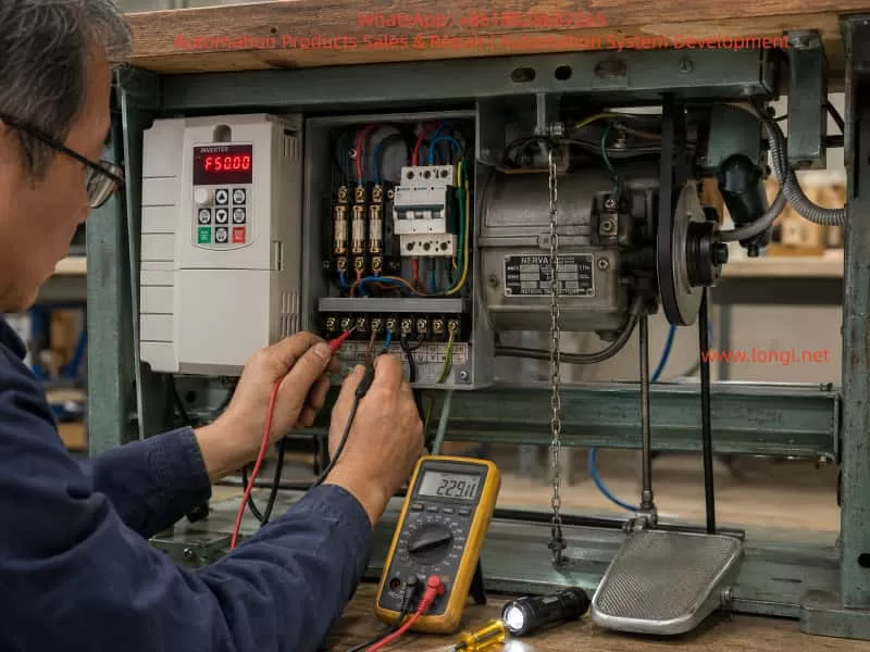
In industrial motor drive applications, especially in textile, sewing, packaging, and light mechanical equipment, one of the most frequently misdiagnosed problems is “motor unable to self-start under inverter control but able to run once externally assisted”.
This case study is based on a real field troubleshooting scenario involving an AT900 series vector VFD (0.75–11kW class) controlling a sewing machine drive system. The system initially presented unstable starting behavior, requiring mechanical assistance via clutch engagement. After systematic diagnosis, the root cause was identified as an intermittent phase loss caused by an aging main contactor/fuse assembly.
The final resolution restored stable and smooth operation without vibration, confirming correct VFD behavior and motor integrity.
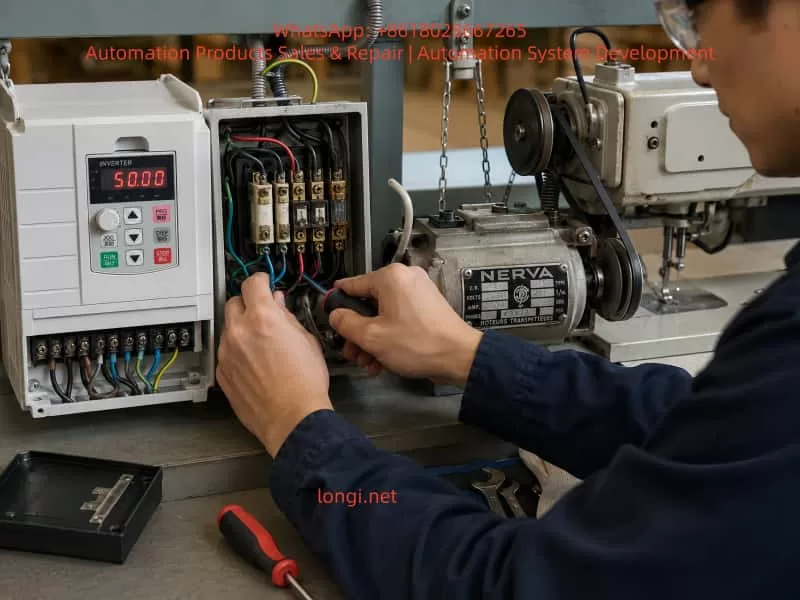
2. System Overview
The drive system consists of:
AT900 series high-performance vector inverter (SVC control mode)
Three-phase induction motor (~0.7–2.2kW class typical for sewing machines)
Mechanical clutch coupling system
Old-generation main contactor and fuse assembly
Direct inverter-to-motor wiring (no encoder feedback)
According to AT900 technical specifications, the inverter supports:
Sensorless vector control (SVC)
V/F control modes
Adjustable torque boost (0.1%–30%)
Starting torque up to 150% depending on configuration
3. Initial Failure Symptoms
The operator reported:
Motor does not start autonomously under RUN command
If the clutch is manually engaged (mechanical rotation applied), motor runs normally
When RUN is triggered, frequency rises smoothly from 0Hz → 15Hz
Motor never reaches stable self-start torque region
Changing torque boost (P04.01) and overload gain (P10.01) had no effect
Additionally:
Motor could not self-start even when unloaded (belt removed test)
Behavior was consistent but intermittent in severity
This symptom pattern strongly indicated a starting torque deficiency or phase imbalance condition, not a parameter tuning issue.
4. Critical Diagnostic Breakthrough
The decisive observation was:
Motor starts normally when externally rotated, but fails to self-start.
This is a classic signature of:
Phase loss (single-phase operation under load)
Intermittent contactor failure
High contact resistance in one phase path
Unequal phase voltage delivery to motor terminals
Such conditions reduce rotating magnetic field symmetry, preventing torque generation at zero speed.
5. Electrical Measurements
After correction and stabilization, measured values were:
Motor phase resistances:
19.7 Ω / 18.9 Ω / 19.7 Ω
Cable/inverter-to-motor resistance:
~0.2 Ω (excellent continuity)
Interpretation:
Parameter
Status
Motor winding symmetry
Acceptable (±4% deviation)
Cable integrity
Excellent
Inverter output
Normal
Historical issue
External phase interruption
The winding values confirmed the motor itself was healthy. Therefore, the fault had to be upstream of the motor terminals.
6. Root Cause Analysis
The final confirmed root cause was:
Intermittent missing phase caused by an aged main contactor / fuse assembly
Mechanism of failure:
Old contactor systems typically suffer from:
Oxidized silver alloy contacts
Arc erosion at switching points
Thermal expansion loosening internal pressure
Intermittent phase dropout under load
High resistance phase causing voltage imbalance
Under VFD operation, this leads to:
One phase voltage drop or distortion
Weak rotating magnetic field
Zero-speed torque collapse
Failure to self-start
Motor only operates when externally “forced into motion”
Once rotating, back-EMF stabilizes the field, allowing operation.
7. Why Parameter Changes Failed
Attempts were made to adjust:
Torque boost (P04.01)
Motor overload gain (P10.01)
However, these parameters only affect:
Low-frequency voltage compensation
Thermal protection scaling
SVC torque estimation correction
They cannot compensate for missing or unstable phase supply.
From AT900 control logic:
Torque generation depends on balanced three-phase voltage vector synthesis
Phase imbalance cannot be corrected by software gain alone
Thus, all tuning attempts were logically ineffective.
8. Final Corrective Action
The site implemented:
Hardware replacement
Replacement of old contactor/fuse assembly
Restoration of stable three-phase supply path
System verification
Balanced phase continuity confirmed
Direct inverter-to-motor wiring validated
No external switching elements remaining
9. Final Performance Result
After correction:
Motor starts reliably every time
Smooth acceleration curve
No vibration during low-speed operation
Correct rotational direction
Stable sewing machine mechanical operation
This confirms:
✔ VFD control system is healthy ✔ Motor insulation and windings are healthy ✔ Mechanical system is properly aligned ✔ Fault was purely upstream electrical distribution
10. Engineering Lessons Learned
10.1 Phase integrity is more important than parameter tuning
In VFD systems, hardware phase continuity is foundational. Any imbalance directly affects:
Torque production
Startup stability
Current waveform symmetry
10.2 “Push-start symptom” is a diagnostic signal
If a motor:
Fails at zero speed
Runs normally after external rotation
Then likely causes are:
Phase loss
Voltage imbalance
Incorrect wiring topology
Weak starting flux condition
10.3 Do not modify VFD parameters before electrical verification
This case confirms a common diagnostic mistake:
Adjusting torque, frequency, and protection parameters without confirming power integrity leads to false troubleshooting cycles.
10.4 Mechanical clutch systems can mask electrical faults
The clutch in this system:
Masked inability to self-start
Allowed motor to bypass zero-speed torque requirement
Created illusion of “weak torque setting”
11. AT900 Series Control Insight
This inverter family uses:
Sensorless vector control (SVC)
Voltage vector synthesis based on phase stability
Torque estimation dependent on current feedback consistency
Therefore:
Any upstream phase distortion directly disrupts vector calculation
Protection systems may not immediately trigger fault codes
Symptoms appear as “soft failure” rather than hard trip
12. Conclusion
This case demonstrates a classic but often misdiagnosed industrial fault:
A motor that cannot self-start under VFD control is not always a tuning problem — it is frequently a power integrity problem upstream of the drive.
The final resolution required:
Rejecting parameter-centric diagnosis
Performing hardware continuity validation
Identifying intermittent phase loss in aging switching components
Replacing degraded contactor/fuse assembly
Once corrected, the system returned to full performance with:
Stable torque at low frequency
Smooth acceleration
Correct direction control
Fully reliable restart behavior
13. Practical Recommendation for Engineers
When encountering similar cases:
Do NOT increase torque boost blindly
Always verify:
Phase-to-phase voltage balance
Contactors / fuses / connectors condition
Continuity under load, not only static measurement
A Systematic Troubleshooting Guide for CSD3-10BX2 Servo Drives Showing an E-Series Fault Code
Servo drive alarms are often misdiagnosed because technicians focus only on the code displayed on the front panel. In many cases, the displayed code is only the final result of an abnormal condition detected by the drive. It does not always identify the actual failed component.
This is especially true for older servo systems such as the Allen-Bradley OEMax CSD3 Plus series. These drives are commonly installed in packaging machines, textile machinery, assembly systems, CNC auxiliary axes, conveyors, and other equipment requiring precise motor positioning and speed control.
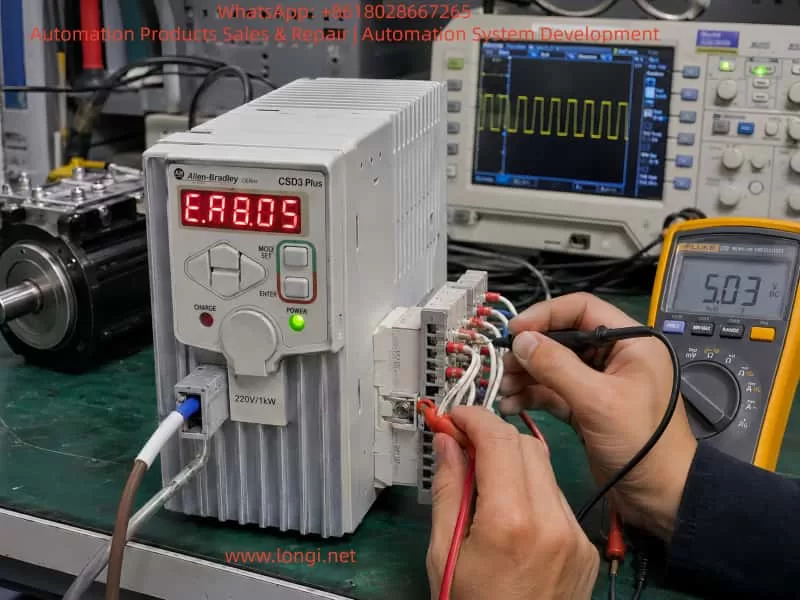
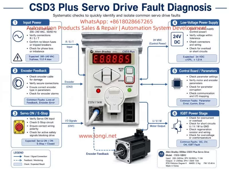
The drive shown in the example is an Allen-Bradley OEMax CSD3 Plus servo drive, model CSD3-10BX2. According to the nameplate, it is a 200–240 Vac three-phase servo drive with an output capacity of approximately 1.0 kW. The drive is manufactured on the RS Automation CSD3 servo platform and uses closed-loop motor feedback, typically through an encoder system.
When this type of drive displays an E-series fault code immediately after power-up, technicians should not immediately conclude that the IGBT module, motor, or encoder is defective. A structured diagnosis is required because the same alarm category may be triggered by encoder feedback failure, low-voltage power supply problems, parameter corruption, internal communication faults, power-stage protection signals, or external enable-chain issues.
This article explains how to diagnose and repair CSD3 Plus servo drive alarms in a systematic way, with particular attention to drives that display an E-type fault code during startup.
1. Identifying the Servo Drive
The unit discussed here is identified as:
Brand: Allen-Bradley OEMax
Series: CSD3 Plus Servo Drive
Model: CSD3-10BX2
Input voltage: 200–240 Vac, three-phase, 50/60 Hz
Input current: approximately 11 A
Output voltage: 0–240 Vac, three-phase
Output capacity: approximately 1.0 kW
Output current: approximately 7.6 A
Manufacturer platform: RS Automation
Country of manufacture: Korea
This is not a standard variable-frequency drive. Although it has three-phase motor output terminals, it is a closed-loop servo drive. Its operation depends on continuous feedback from the motor encoder.
A normal VFD can control a standard induction motor mainly by generating a variable frequency and voltage. A servo drive must also monitor motor position, speed, direction, acceleration, deceleration, torque demand, and feedback integrity. For this reason, servo drives are much more sensitive to encoder faults, parameter mismatches, power-supply instability, and communication errors.
2. Why an E-Series Alarm Requires Careful Diagnosis
In many servo systems, an E-series display indicates that the drive has detected an abnormal condition during initialization, standby, servo-enable operation, or motor control.
The fault may be related to one of the following areas:
Encoder communication failure
Encoder power-supply failure
Motor identification mismatch
Incorrect servo parameters
Internal CPU self-test failure
EEPROM or parameter memory failure
Control board to power board communication fault
DC bus voltage detection failure
Current feedback circuit fault
IGBT gate-driver protection signal
External Servo ON input problem
Emergency stop circuit open
Positive or negative travel-limit signal active
Internal low-voltage power-supply instability
Therefore, the displayed fault code should be treated as a starting point for diagnosis, not as a final conclusion.
A repair technician should first determine when the alarm occurs:
Immediately after control power is applied
After main power is applied
Only after Servo ON is activated
When the motor starts moving
During acceleration
During high-speed operation
During deceleration
Randomly after the machine has been running for some time
The timing of the alarm is one of the most useful clues in servo-drive troubleshooting.
3. The Importance of Startup Sequence
A servo drive performs several internal checks before it is ready to operate. During startup, the drive may verify the following conditions:
Control power supply voltage
Internal 5 V, 12 V, 15 V, and logic power rails
CPU operation and reset status
EEPROM or parameter memory integrity
Encoder interface condition
Motor feedback communication
DC bus voltage level
Pre-charge circuit condition
Current sensor zero point
Power-stage communication
IGBT or IPM protection feedback
Servo-enable input status
Emergency stop circuit status
Positive and negative travel limits
Internal temperature or thermal-protection status
If any of these checks fails, the drive may refuse to enter Ready status and display an alarm.
For this reason, a drive that alarms immediately after power-up should not automatically be classified as a power-stage failure. In many cases, the fault is located in the encoder feedback circuit, the low-voltage power supply, or the control board.
4. The Most Common Causes of CSD3 Plus Startup Alarms
4.1 Encoder Feedback Failure
Encoder-related problems are among the most common causes of servo-drive alarms.
The servo drive needs feedback information from the motor encoder to establish a closed control loop. If the encoder signal is absent, unstable, corrupted, or incompatible, the drive may generate an E-series error before the motor is allowed to run.
Common causes include:
Loose encoder connector
Bent or oxidized connector pins
Broken encoder cable inside a cable carrier
Oil contamination inside the connector
Coolant ingress into the motor connector
Damaged cable shielding
Incorrect cable wiring
Encoder power supply missing
Encoder internal circuit failure
Motor encoder damaged after collision or vibration
Encoder cable routed together with motor power cables
Poor grounding causing electrical interference
Incorrect replacement motor or encoder type
In many industrial machines, the encoder cable is repeatedly bent inside a drag chain. The cable may look normal from outside while one or more internal conductors are broken. This is especially common near the motor connection, near the machine frame, or at the fixed end of the cable carrier.
A damaged encoder cable can create intermittent faults. The machine may work normally when stationary but alarm during motion, vibration, or axis travel.
4.2 Encoder Power Supply Failure
The encoder itself may be healthy while the drive is unable to provide correct power to it.
The encoder interface usually receives a regulated low-voltage supply from the servo drive. Depending on the design, this may include 5 V, 12 V, or other low-voltage rails.
The following checks are important:
Is the encoder supply voltage present?
Is the supply stable after power-up?
Does the voltage collapse when the encoder cable is connected?
Is there excessive ripple on the encoder supply?
Does the power supply remain stable during Servo ON?
Is the encoder interface voltage affected by cable movement?
If the drive produces a stable 5 V supply with the encoder unplugged, but the voltage falls sharply when the encoder is connected, the likely causes are:
Short circuit inside encoder cable
Short circuit inside motor encoder
Moisture in the encoder connector
Failed TVS protection diode on the drive interface
Shorted filter capacitor
Damaged encoder interface IC
Damaged shielding or grounding connection
Repeatedly powering the drive under a shorted encoder condition may damage the internal low-voltage regulator. Therefore, excessive repeated testing should be avoided.
4.3 Parameter Corruption or Motor Mismatch
Servo drives are not universal devices. The drive parameters must match the connected servo motor and encoder.
If the drive has been repaired, reset, replaced, or incorrectly configured, it may not recognize the motor correctly.
Typical causes include:
Factory reset performed without parameter backup
Incorrect motor model selected
Incorrect encoder type configured
Wrong motor capacity parameter
Wrong control mode selected
Incorrect electronic gear ratio
Incorrect encoder resolution setting
Absolute encoder mode set incorrectly
Parameter memory corruption
Replacement drive installed without transferring original settings
A parameter mismatch may cause the drive to alarm immediately, or it may allow Servo ON but alarm when motion begins.
It is important not to reset the drive to factory defaults without recording the original parameters. On older machines, the original parameter list may no longer be available. A full reset can cause new problems such as incorrect direction, excessive gain, overtravel, homing failure, or machine collision.
4.4 External Servo ON, Emergency Stop, or Limit Circuit Problems
A servo drive often depends on external digital inputs before it can enter normal operating condition.
These may include:
Servo ON
Alarm reset
Emergency stop
Safety relay output
Positive travel limit
Negative travel limit
External interlock
Brake release signal
PLC enable command
Controller readiness signal
If any of these signals is missing or in the wrong logic state, the drive may not enable correctly.
Typical external causes include:
Failed PLC output
24 V control power missing
Burned relay contact
Loose terminal screw
Emergency stop button activated
Door safety switch open
Broken limit switch cable
Incorrect NPN/PNP wiring
Incorrect common terminal connection
Improper input polarity
External safety circuit not reset
Before opening the servo drive, it is important to verify the external control wiring. A normal drive can be incorrectly diagnosed as defective if the safety chain is open.
5. Why the IGBT Module Should Not Be the First Suspect
When a servo drive shows an alarm, many technicians immediately inspect the IGBT module. This is understandable because IGBTs are critical components in the output stage. However, they are not always the most likely cause of a startup alarm.
A failed IGBT module often produces more obvious symptoms, such as:
Input breaker trips immediately
Main fuse is blown
DC bus is shorted
P-to-N resistance is abnormally low
U, V, or W output is shorted to DC bus
Drive alarms immediately after Servo ON
Motor vibrates sharply and faults
Severe overcurrent alarm
Burn marks on the power board
Abnormal heating
Failed pre-charge circuit
Brake transistor short circuit
If the control power LED is on and the drive displays an alarm without tripping the breaker, the first inspection should usually focus on low-voltage supplies, encoder circuits, control board signals, and external control inputs.
This does not mean that the power stage is definitely good. A power-stage fault can also occur without a hard short circuit. For example:
IGBT gate-driver voltage may be missing
Current sensor output may be incorrect
IPM fault output may be permanently active
Power board communication may be lost
Brake circuit feedback may be abnormal
One phase may have a gate-drive problem
DC bus voltage sensing may be incorrect
However, these conditions require deeper testing than a simple resistance check of U, V, and W terminals.
6. External Inspection Before Removing the Drive
Before sending the drive for repair or opening the unit, perform a complete external inspection.
6.1 Record the Fault Condition
Document the following information:
Full servo drive model number
Serial number
Exact displayed fault code
Whether the code is steady or flashing
Whether the alarm appears immediately after power-up
Whether the motor moves before the alarm
Whether the fault occurs only after Servo ON
Whether the fault occurs only during motion
Recent machine events before the fault
Previous repairs or replacement parts
Whether the machine had a collision
Whether the machine was exposed to water, oil, lightning, power loss, or voltage instability
This information is extremely valuable during bench repair.
6.2 Inspect Motor and Encoder Connections
Check the following carefully:
Encoder connector fully locked
Motor power connector secure
Connector pins not bent or oxidized
No coolant, oil, or water inside connectors
Cable shielding intact
Cable jacket not damaged
No sharp bending near connectors
Encoder cable separated from U/V/W motor cables
No cable crushed inside machine frame
No drag-chain damage
Motor brake wiring intact
Proper ground connection present
The encoder cable should not be routed together with motor output cables for long distances. The high-frequency switching noise from the servo output can interfere with weak feedback signals.
6.3 Verify Input Power
The CSD3-10BX2 is intended for 200–240 Vac three-phase input.
Measure:
R-S voltage
S-T voltage
R-T voltage
Voltage balance between phases
Voltage drop during startup
Main contactor condition
Fuse condition
Terminal tightness
Transformer output voltage, if applicable
A serious mistake is applying 380 Vac three-phase power to a 220 Vac servo drive. This can cause immediate and extensive damage to the rectifier stage, DC bus capacitors, low-voltage power supply, power module, and control board.
Always confirm actual voltage with a meter. Do not rely only on cabinet labels.
7. Internal Repair Procedure for a Drive That Alarms with Minimal External Wiring
If the drive continues to display the same alarm after external wiring, motor, and encoder issues have been excluded, internal diagnosis is required.
A proper repair sequence should proceed from high-energy power circuits toward low-voltage logic circuits.
7.1 Check Rectifier and DC Bus Circuit
After disconnecting power and allowing sufficient time for the DC bus capacitors to discharge, inspect:
Three-phase rectifier bridge
DC bus terminals P and N
Main filter capacitors
Pre-charge resistor
Pre-charge relay
Brake transistor
Brake resistor terminals
DC bus voltage sensing circuit
Bus capacitor ESR and leakage
Burnt resistors or damaged tracks
If P and N are directly shorted, isolate the possible fault sections one by one:
IGBT or IPM module
Brake transistor
DC bus capacitors
Rectifier bridge
Snubber circuit
Power board contamination
A direct bus short should never be ignored. Do not repeatedly apply power to a drive with a suspected DC bus short.
7.2 Check IGBT or IPM Module
The power module should be tested carefully.
Measure:
P to U, V, W
N to U, V, W
U to V
V to W
U to W
Gate-driver pins if accessible
Fault feedback output
Driver supply voltage
Isolation between power stage and control stage
A simple diode-test reading is useful, but it is not enough to prove that the IGBT stage is healthy.
The power stage may still fail because of:
Missing gate-drive voltage
Failed gate resistor
Failed optocoupler
Faulty driver IC
Current sensor offset
Internal protection latch
One phase not switching correctly
Power board connector oxidation
Cracked solder joints
Temperature sensor fault
For this reason, an oscilloscope is often required to verify gate signals and driver supply rails.
7.3 Check Low-Voltage Power Supplies
Low-voltage power supply failure is very common in older servo drives.
The following rails should be checked:
+5 V
+3.3 V
+12 V
+15 V
-15 V, where applicable
Isolated driver supply rails
Encoder supply voltage
CPU supply voltage
Reference voltage circuits
Typical failures include:
Aged electrolytic capacitors
High ESR capacitors
Failed switching controller IC
Failed optocoupler
TL431 reference circuit failure
Shorted secondary diode
Failed DC/DC converter
Cracked solder joint
Damaged regulator IC
Open SMD fuse
Burnt startup resistor
If the supply voltage is low or unstable, the CPU may reset repeatedly, the encoder interface may malfunction, and the drive may display an internal alarm even though the main power stage is not defective.
7.4 Check Encoder Interface Circuit
The encoder interface should be treated as a priority area.
Inspect and test:
Encoder connector solder joints
Connector pin condition
5 V supply fuse or resettable fuse
TVS protection diodes
Common-mode choke components
Data-line protection arrays
Differential receivers
Differential transmitters
Optocouplers, if used
Interface IC supply voltage
Filter capacitors
Grounding and shield connection
A failed TVS diode can short the encoder supply line to ground. A damaged receiver IC can prevent encoder communication even when the encoder itself is good. A cracked connector solder joint can create intermittent feedback loss.
In environments with oil mist, coolant, vibration, or frequent cable movement, encoder-interface failures are common.
7.5 Check Control Board and Parameter Memory
If the power section, low-voltage supplies, and encoder interface appear normal, inspect the control board.
Important areas include:
Main MCU or DSP
Crystal oscillator
Reset circuit
EEPROM or Flash memory
CPU supply rail
Watchdog circuit
Board-to-board communication
Power board communication connector
Corrosion around IC pins
Solder cracks under large components
Parameter memory integrity
Communication transceivers
Faults in this area may require comparison with a known-good drive, oscilloscope testing, logic analysis, and EEPROM programming tools.
If a replacement control board is installed, parameter compatibility must be confirmed before attempting operation.
8. Isolation Testing: Internal Fault or External Fault?
A useful method is to separate the problem into two categories:
Fault caused by the drive itself
Fault caused by external motor, cable, encoder, PLC, or safety circuit
Scenario A: The Drive Alarms with External Wiring Removed
If the drive still alarms with the following disconnected:
Motor power cable
Encoder cable
PLC control wiring
Communication cable
External I/O
Servo ON signal
Brake wiring
then the fault is more likely inside the drive.
Possible internal causes include:
Low-voltage power supply failure
Control board failure
Parameter memory problem
Encoder interface fault
Power board communication fault
DC bus sensing failure
Current-sensor fault
Gate-driver protection fault
Internal CPU self-test failure
However, note that some servo drives are designed to alarm if no encoder is connected. Therefore, this test should ideally be compared with a known-good drive of the same model.
Scenario B: The Drive Is Normal Without the Motor but Alarms When the Motor Is Connected
This condition strongly suggests an external problem.
Priority suspects include:
Encoder cable
Motor encoder
Motor power cable
Motor winding fault
Brake coil fault
Incorrect motor
Incorrect encoder type
Cable shielding issue
Incorrect wiring sequence
Connector contamination
Motor-to-ground insulation failure
The best way to confirm this is through substitution testing:
Test with a known-good motor.
Test with a known-good encoder cable.
Test the motor on another compatible drive.
Test the drive with another compatible motor.
Measure encoder supply voltage with and without the cable connected.
Check motor winding resistance and insulation resistance.
Substitution testing is often more reliable than simple resistance measurements.
9. Common Misdiagnoses During Servo Drive Repair
Misdiagnosis 1: Every E-Series Fault Is an Encoder Fault
Encoder faults are common, but they are not the only cause.
An E-series fault may also result from:
CPU self-test failure
EEPROM corruption
Internal communication failure
Current feedback circuit problem
DC bus sensing error
Power board protection signal
Low-voltage supply instability
Parameter mismatch
External enable-chain issue
Replacing the encoder without testing the encoder supply and interface circuit may waste time and money.
Misdiagnosis 2: No U/V/W Short Means the Power Stage Is Good
A power module may pass a basic diode test and still be defective.
Possible hidden failures include:
Gate drive missing on one phase
Current feedback abnormal
IGBT protection feedback stuck active
Driver supply voltage missing
Brake circuit malfunction
Power-stage communication fault
Thermal sensor fault
Cracked solder joint
Output waveform distortion
A proper diagnosis requires more than checking terminal resistance.
Misdiagnosis 3: Resetting Parameters Immediately
Factory reset should not be the first action.
Resetting the drive can erase machine-specific settings such as:
Motor model
Encoder type
Electronic gear ratio
Position command mode
Speed loop gain
Position loop gain
Acceleration and deceleration parameters
Homing settings
Input logic
Output logic
Torque limit
Travel-limit configuration
On an older machine, these parameters may be impossible to recover. A parameter reset can turn a repairable fault into a commissioning problem.
Misdiagnosis 4: Ignoring Cable and Connector Problems
A servo drive may test normal on the repair bench but fail again after installation.
Common reasons include:
Broken wire inside drag chain
Intermittent encoder cable
Loose motor connector
Contaminated encoder plug
Poor grounding
External electrical noise
Damaged PLC output
Unstable 24 V supply
Poor cabinet wiring
Loose terminal screw
A proper repair should include dynamic testing with a compatible motor and encoder whenever possible.
10. Recommended Standard Diagnostic Workflow
For a CSD3-10BX2 or similar CSD3 Plus servo drive, the following workflow is recommended.
Step 1: Record the complete model number and fault condition
Document the exact display, fault timing, and machine behavior.
Step 2: Verify the input voltage
Confirm that the drive receives 200–240 Vac three-phase input and is not connected to 380 Vac.
Step 3: Inspect motor, encoder, brake, and control wiring
Check connectors, cable condition, shield, grounding, and drag-chain movement.
Step 4: Check encoder power supply
Measure encoder supply voltage and observe whether it collapses when the encoder is connected.
Step 5: Check Servo ON and external safety inputs
Confirm 24 V control power, emergency stop loop, limit switches, PLC output, and enable logic.
Step 6: Reduce the system to minimum wiring
Disconnect unnecessary external signals and observe the drive behavior under controlled conditions.
Step 7: Inspect the DC bus and power circuit
Check rectifier bridge, pre-charge circuit, DC bus capacitors, brake transistor, and IGBT/IPM module.
Test protection components, interface ICs, connector solder joints, and encoder supply circuitry.
Step 10: Inspect control board and parameter memory
Check MCU, oscillator, reset circuit, EEPROM, communication signals, and board-to-board connectors.
Step 11: Perform motor matching and no-load testing
Use a compatible motor and encoder to test Servo ON, direction, low-speed rotation, and alarm response.
Step 12: Perform dynamic and thermal testing
Run repeated start-stop tests, acceleration tests, low-speed and high-speed tests, and temperature monitoring.
11. Conclusion
Allen-Bradley CSD3 Plus servo drives such as the CSD3-10BX2 should not be diagnosed only by the front-panel alarm code.
When an E-series fault appears, especially immediately after power-up, the most important areas to investigate are:
Encoder feedback system
Encoder power supply
Motor and cable condition
External Servo ON and safety circuit
Low-voltage power supplies
Control board self-test
Parameter memory
Power board communication
DC bus voltage detection
Current feedback and gate-driver protection circuits
In many cases, the actual failure is not the IGBT module. More common causes include broken encoder cables, damaged connectors, failed 5 V encoder supply circuits, aged low-voltage capacitors, parameter mismatch, internal interface faults, and unstable control power.
A reliable repair process should follow a complete diagnostic chain:
Fault display → external wiring → encoder feedback → control power → low-voltage rails → power stage → control board → dynamic motor test.
This method reduces unnecessary component replacement, improves repair accuracy, and provides a much higher chance that the servo drive will remain stable after it is returned to service.
In hydraulic servo systems used in injection molding machines, hydraulic presses, die-casting machines, rubber machinery, and other industrial equipment, the Inovance IS580 hydraulic servo drive performs several critical functions. These include motor speed control, pressure closed-loop control, flow closed-loop control, temperature protection, and hydraulic response management.
When an IS580 drive reports faults such as Err45 and Err46, the equipment may fail to start, stop immediately after startup, or remain locked in an alarm state. These faults should not be treated simply as “the drive is defective.” It is also not appropriate to immediately replace the IGBT module or power board.
In many cases, Err45 and Err46 are related to the motor temperature feedback circuit, pressure sensor feedback circuit, 24 VDC control supply, analog input wiring, common reference terminals, or the control board signal-conditioning circuit.
This article uses a typical Inovance hydraulic servo drive, such as the IS580T070-R1-1-EST, 37 kW, 380–480 VAC input model, as an example. It explains how to identify, diagnose, and repair suspected Err45 and Err46 faults in a systematic manner.
1. Confirm the Actual Alarm Code Before Starting Diagnosis
Before troubleshooting, the first step is to confirm the real alarm code.
When a mobile phone records a seven-segment LED display, the displayed characters may appear incomplete, distorted, overlapped, or flashing. For example, “Err45” or “Err46” may appear in a video as something similar to “E8.8.85,” “E8.8.86,” or other unclear characters.
This happens because most LED displays use multiplex scanning. The drive scans each digit very quickly. Human eyes see a complete number, but the camera shutter may capture only part of the scan cycle.
Therefore, before diagnosing the drive:
Record a video instead of taking only a single photo.
Use slow-motion recording if available.
Film the display from close range.
Observe whether the fault code is fixed or alternates between two alarms.
Record whether the alarm occurs immediately after power-on, when the motor starts, or after running for a period of time.
Take photos of the drive terminals, motor terminal box, pressure sensor, and external wiring.
If Err45 and Err46 appear alternately, this usually indicates two different feedback-related faults rather than one main power circuit failure.
2. Basic Meaning of Err45 and Err46
For an Inovance IS580 hydraulic servo system, the following diagnostic direction should be considered first:
Fault Code
Main Diagnostic Direction
Related Components
Err45
Motor temperature feedback fault, PTC circuit abnormality, actual motor overheating
Motor temperature cable, PTC sensor, thermal switch, connector, terminal block, control board temperature input
Err46
Pressure sensor feedback fault, pressure analog signal out of range, sensor supply problem
Pressure sensor, 24 VDC supply, analog input, shielded cable, analog common terminal, control board analog input circuit
Different drive firmware versions, machine builders, and parameter configurations may use slightly different alarm descriptions. Therefore, the final diagnosis should always be confirmed against the correct IS580 manual, the machine electrical drawing, and the original parameter backup.
However, both Err45 and Err46 are generally feedback-detection faults. They are not typical faults such as IGBT short circuit, DC bus undervoltage, output phase loss, or braking unit failure.
For this reason, the correct troubleshooting sequence is:
3. Why Pressure Feedback Is So Important in a Hydraulic Servo System
A standard inverter can run a motor when it receives a run command and frequency reference. A hydraulic servo drive is more complex.
In a hydraulic servo system, the drive adjusts motor speed and torque according to pressure and flow feedback signals. The control logic can be simplified as follows:
Pressure command → Actual pressure feedback → Error calculation → Motor speed adjustment → Hydraulic pump output adjustment → Actual pressure reaches the target value.
If the pressure sensor signal is missing, unstable, out of range, incorrectly configured, or disconnected, the drive cannot accurately determine the actual hydraulic pressure.
To avoid uncontrolled pressure increase, pump overload, low-pressure operation, or dangerous hydraulic movement, the drive may stop and generate a pressure feedback alarm.
Therefore, when Err46 occurs, it does not always mean that the hydraulic pressure itself is abnormal. In many cases, it means that the drive cannot read a valid pressure signal.
Possible causes include:
No 24 VDC supply to the pressure sensor;
Loose pressure sensor connector;
Broken pressure signal wire;
Open or incorrect analog common terminal;
Wrong setting between 0–10 V and 4–20 mA;
Damaged pressure sensor;
Moisture or oil contamination in the connector;
Incorrect shielding or severe electrical interference;
Analog input circuit failure on the drive control board;
External 24 VDC supply fluctuation.
4. Err45: Motor Temperature Protection Circuit
Hydraulic servo motors are commonly equipped with an internal temperature protection element. Typical types include:
PTC thermistor;
NTC thermistor;
Normally closed or normally open thermal switch;
KTY temperature sensor;
Motor temperature feedback integrated into the encoder connector.
In industrial servo motors, PTC protection is very common. At normal temperature, the PTC resistance remains low. When the motor reaches the protection temperature, the resistance rises sharply. The drive monitors this circuit to determine whether the motor is overheating.
When Err45 occurs, it does not automatically mean that the motor winding is burnt.
In real maintenance cases, Err45 is often caused by an abnormal temperature feedback circuit rather than true motor overheating.
Common causes include:
Broken motor temperature cable;
Loose aviation connector;
Oxidized connector pins;
Oil or water inside the motor terminal box;
Cable insulation damage caused by heat;
Open-circuit PTC sensor;
Incorrect wiring after maintenance;
Loose intermediate terminal block;
Damaged temperature input circuit on the control board;
Actual motor overheating caused by overload, poor ventilation, or hydraulic system problems.
Hydraulic servo motors often operate under high load, high oil temperature, and high ambient temperature. If the hydraulic system has continuous overflow, pump seizure, poor cooling, excessive pressure, or heavy mechanical load, the motor may actually overheat.
5. Field Inspection Procedure for Err45
Step 1: Check Whether the Motor Is Actually Overheating
After stopping the equipment, use an infrared thermometer to measure:
Motor housing temperature;
Motor terminal box temperature;
Cooling fan area temperature;
Hydraulic pump temperature;
Hydraulic oil temperature;
Drive heatsink temperature.
If the motor is extremely hot, has a burning smell, or the cooling fan is not operating, mechanical and cooling problems must be resolved first.
Check the following items:
Is the motor fan running?
Is the airflow path blocked?
Is the hydraulic oil temperature too high?
Is the oil cooler working properly?
Is the hydraulic pump mechanically overloaded?
Is the relief valve continuously bypassing oil?
Is the system pressure higher than the normal setting?
Are the motor parameters correct?
Is the motor power rating suitable for the hydraulic pump?
Step 2: Measure the Motor Temperature Circuit
Disconnect the main power supply and wait until the DC bus is fully discharged. A 37 kW drive contains significant stored DC bus energy. Do not touch control terminals or power terminals immediately after power-off.
Locate the motor temperature feedback wires and measure the resistance between the two temperature terminals.
Short circuit, damaged component, incorrect wiring
Stable resistance within expected range
Temperature circuit is probably normal
Resistance changes while moving the cable
Broken conductor, loose plug, poor crimping
Resistance increases sharply when motor is hot
Motor may actually be overheating or PTC is operating
The exact resistance value depends on the motor manufacturer and sensor type. Do not judge the circuit only by a single resistance value. Compare with a known-good motor if possible, or refer to the motor documentation.
Step 3: Inspect Both Motor Side and Drive Side
Many technicians inspect only the drive terminal. However, the motor-side connector is often the real source of the fault.
Pay particular attention to:
Motor aviation connector pins;
Encoder connector;
Terminal box wiring;
Cable chain bending points;
Oil contamination;
Moisture ingress;
Loose terminal screws;
Oxidized connectors;
Improper reconnection after previous maintenance.
The temperature feedback circuit must be checked from the motor all the way to the drive input terminal.
6. Err46: Pressure Sensor Fault Diagnosis
Hydraulic pressure sensors usually use one of the following output formats:
0–10 V;
0–5 V;
4–20 mA.
The most common types are 0–10 V and 4–20 mA.
A typical pressure sensor may have three or four wires:
Positive supply, usually +24 VDC;
Negative supply, 0 VDC;
Signal output, 0–10 V or 4–20 mA;
Shield wire, depending on the sensor type.
Before checking the wiring, confirm the actual sensor type and make sure the drive parameters match it.
For example, if the sensor is 4–20 mA but the drive is configured for 0–10 V, the drive may report Err46 even though the sensor itself is healthy.
7. Three-Step Pressure Sensor Test Method
Step 1: Check the Sensor Supply Voltage
Use a multimeter in DC voltage mode and measure the sensor power supply terminals.
Typical expected values include:
Approximately 24 VDC;
In some systems, 10 VDC or 12 VDC;
The voltage should remain stable and should not collapse during alarm conditions.
If the pressure sensor has no supply voltage, inspect:
Drive 24 VDC output;
External switching power supply;
Fuse;
Terminal block;
Intermediate relay;
Common 0 VDC wiring;
Broken cable;
Control board 24 VDC output circuit.
If multiple sensors lose power at the same time, the problem is more likely related to the common power supply or common wiring than to a single sensor.
Step 2: Check the Pressure Signal Output
For a 0–10 V pressure sensor, measure the signal wire relative to the analog common terminal.
Normally, the output voltage should change smoothly with hydraulic pressure. For example:
Near 0 V when pressure is low;
Approximately 4–6 V at medium pressure;
Close to 10 V at full-scale pressure.
For a 4–20 mA sensor, measure the current in series or measure the voltage across a known sampling resistor.
Typical diagnostic conclusions are:
Signal Condition
Possible Cause
Signal always 0 V
No sensor supply, broken signal wire, failed sensor
Signal always at maximum value
Signal shorted to 24 V, failed sensor, actual pressure overload
Even if the sensor output is normal, verify that the signal actually reaches the drive.
Measure the signal at several locations:
At the pressure sensor output;
At the intermediate terminal block;
At the drive analog input terminal;
At the analog common terminal;
At the control board connector.
If the signal is correct at the sensor but missing at the drive, the fault is in the cable, terminal block, connector, or wiring arrangement.
If the signal is correct at the drive terminal but Err46 remains active, the control board analog input circuit becomes a strong suspect.
8. Why Err45 and Err46 Can Occur Together
Err45 and Err46 relate to different feedback signals, but they may appear together because of a shared fault source.
Common shared causes include the following.
1. Abnormal 24 VDC Control Supply
Pressure sensors usually depend on 24 VDC. Some encoder interfaces, external temperature modules, and control circuits may also depend on the same low-voltage supply.
If the 24 VDC power supply is unstable, overloaded, shorted, or heavily fluctuating, multiple feedback signals may become abnormal.
2. Loose or Open Common 0 VDC
In analog control systems, 0 VDC is not only the negative supply wire. It is also the signal reference point.
If the pressure sensor signal wire remains connected but the analog common terminal is open, the drive may read unstable, floating, saturated, or incorrect voltage values.
A common-terminal problem may also affect other low-voltage detection circuits.
3. Oil, Water, or Corrosion at the Terminal Block
Hydraulic equipment often operates in oily environments. If the electrical cabinet sealing is poor, oil mist, moisture, dust, and corrosion may enter the terminal area.
This can cause:
High-resistance leakage;
Analog signal drift;
Oxidized terminals;
Short circuits;
24 VDC leakage to ground;
Increased contact resistance;
Unstable feedback signals.
4. Signal Cables Installed Together With Motor Cables
If pressure sensor cables, temperature feedback wires, and encoder cables are routed together with U/V/W motor output cables for a long distance, they may be affected by PWM switching interference.
This can cause:
Unstable pressure feedback;
Analog input over-range alarms;
Encoder communication errors;
Temperature input misjudgment;
Unstable motor operation.
Analog signal cables should use shielded twisted-pair cable and should be routed separately from power cables. Shield grounding should follow the original machine design and the drive manufacturer’s requirements.
5. Control Board Analog Input Circuit Failure
If the pressure sensor, external wiring, 24 VDC supply, and terminal block all test normally, the control board becomes a likely fault source.
Common damaged parts on the control board include:
Analog input operational amplifiers;
TVS surge protection devices;
Current-limiting resistors;
Optocouplers;
24 VDC to 5 VDC or 3.3 VDC regulators;
ADC input circuits;
Connector pins;
Temperature detection comparators;
MCU peripheral sampling circuits.
Such faults usually require board-level inspection, component-level measurement, and analog signal simulation.
9. Do Not Directly Short the Motor Temperature Protection Input
Some technicians may short the motor temperature protection input temporarily in order to make the machine run.
This is risky.
Shorting the temperature input may temporarily remove Err45, but it also disables motor thermal protection. If the motor is actually overheating because of poor cooling, pump overload, blocked oil flow, high hydraulic pressure, or fan failure, continued operation may cause:
Motor winding burnout;
Encoder damage;
Bearing failure;
Hydraulic pump seizure;
Drive overcurrent;
IGBT module damage;
Mechanical equipment failure.
A temporary simulation may be used only by experienced personnel for diagnostic purposes and only after confirming that the motor temperature is safe. The original thermal protection must be restored after diagnosis.
Similarly, do not blindly inject a voltage or connect a resistor to simulate the pressure sensor signal. Incorrect pressure simulation can cause dangerous hydraulic movement or incorrect pressure control.
10. Recommended Complete Troubleshooting Sequence
For an Inovance IS580 hydraulic servo drive showing Err45 and Err46, use the following sequence.
Step 1: Record the Current Condition and Save Parameters
Before resetting the drive or disconnecting power, record:
Drive model;
Alarm code;
Parameter group settings;
Motor nameplate;
Pressure sensor nameplate;
Control terminal wiring;
Machine electrical drawings;
Machine condition when the alarm occurs;
Whether the motor, sensor, pump, or control board was recently replaced.
If the drive can still access the parameter menu, save the parameters before making changes. Pressure signal type, scaling, zero-point adjustment, maximum pressure setting, and control mode can all affect fault diagnosis.
Step 2: Check the Control Power Supply
Measure:
Drive 24 VDC control output;
External 24 VDC power supply;
Pressure sensor supply voltage;
Stability between 24 VDC and 0 VDC;
Insulation between 24 VDC and ground;
Whether the control voltage drops when the alarm occurs.
Step 3: Check the Motor Temperature Circuit
Measure:
Temperature feedback resistance;
Motor-side connector;
Drive-side terminal;
Intermediate terminal block;
Cable bending points;
Resistance variation while moving the cable.
Step 4: Check the Pressure Sensor Circuit
Measure:
Sensor supply voltage;
Sensor output signal;
Sensor signal type;
Drive parameter settings;
Whether the signal changes with pressure;
Connector contamination, looseness, or corrosion.
Step 5: Check Analog Common and Shielding
Confirm:
Analog common terminal connection;
Relationship between sensor 0 VDC and drive analog common;
Shield wire grounding method;
Separation between analog signal cables and motor power cables;
Absence of incorrect grounding or multiple grounding points.
Step 6: Inspect the Control Board Only After External Circuits Are Confirmed Normal
If all external checks are normal, proceed to control board inspection.
Check whether:
The analog input can receive a standard test voltage;
The temperature input can recognize a correct resistance value;
24 VDC, 5 VDC, and 3.3 VDC supplies are stable;
The analog channel is damaged;
The board connector solder joints are loose;
There is corrosion, oil contamination, or moisture damage on the board.
11. Practical Advice for Machine Operators
For non-professional users, the following basic checks can be completed before sending the drive for repair:
Check whether the servo motor is excessively hot.
Check whether the motor cooling fan operates normally.
Check whether the motor temperature connector is loose.
Check whether the pressure sensor connector is loose, oily, damaged, or corroded.
Measure whether the pressure sensor has a stable 24 VDC supply.
Measure whether the pressure signal changes with hydraulic pressure.
Check whether sensor cables are routed together with motor power cables.
Check whether drive control terminals show signs of moisture, corrosion, overheating, or loose wiring.
Do not short the motor temperature protection terminal permanently.
Do not replace the IGBT module before checking the feedback circuits.
12. Conclusion
When an Inovance IS580 hydraulic servo drive reports suspected Err45 and Err46 faults, the first diagnostic focus should be the motor temperature feedback circuit and pressure sensor feedback circuit, not the IGBT module or main power board.
Err45 requires inspection of the motor PTC circuit, temperature cable, aviation connector, terminal block, motor cooling condition, and hydraulic load.
Err46 requires inspection of the pressure sensor supply voltage, output signal, analog input type, analog common terminal, shielding, and control board analog input circuit.
If both faults occur together, special attention should be given to the 24 VDC control supply, analog common wiring, control cable harness, terminal contamination, and control board connector condition.
The most effective diagnostic method is to follow the signal path step by step:
This process allows technicians to quickly distinguish between an external wiring or sensor problem and an internal drive control board fault.
For high-power hydraulic servo drives such as 37 kW units, blindly bypassing protection circuits, forcing the machine to run, or replacing the power module without testing the feedback system can significantly increase repair cost and equipment risk. The correct approach is to first verify whether the feedback signals are real, stable, correctly wired, and correctly matched to the drive parameters.