
Danfoss FC102 Series User Manual Guide: LCP Panel, Parameter Copying, Terminal Start/Reverse Control, 0-10V Potentiometer Reference and Alarm Troubleshooting
The Danfoss VLT HVAC Drive FC102 is designed for HVAC systems such as fans, pumps, cooling towers, air handling units and building automation. Compared with compact general-purpose drives, FC102 has more I/O resources, stronger LCP functions and HVAC-oriented features such as no-flow detection, dry-pump protection, sleep mode, fire mode, cascade control and bypass functions. For service work, the practical focus is clear: use the LCP panel, back up and copy parameters, restore defaults, wire terminal start and interlock, use terminal 53 for 0-10V speed reference, and diagnose alarms in the right order.
This guide is based on the FC102 operating manual. Always verify the nameplate, power class, option cards, terminal diagram, safety circuit and mechanical direction limits before applying settings.
LCP Panel: Status, Quick Menu, Main Menu and Alarm Log
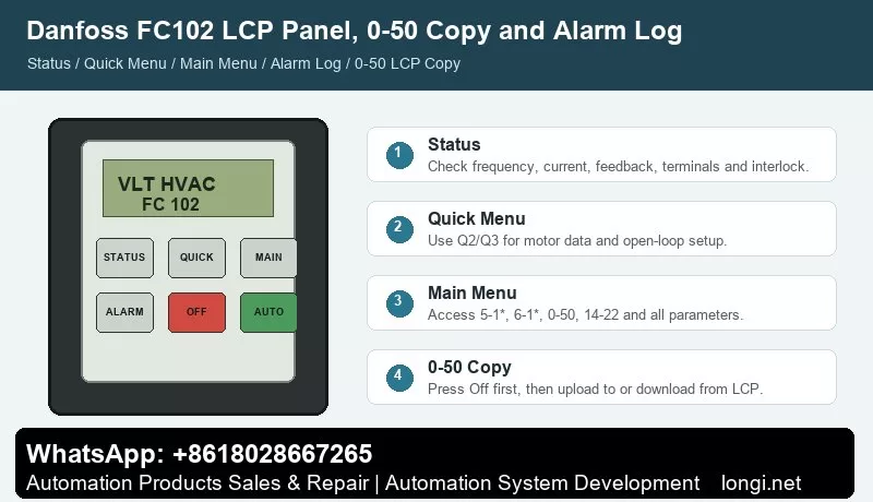
FC102 uses the LCP as the main service interface. Status shows operating values. Quick Menu supports guided commissioning. Main Menu gives access to all parameters. Alarm Log helps trace previous trips and warnings.
Use Status to check output frequency, reference, motor current, feedback, terminal status and warning state. If the display shows auto remote coast or alarm 60 external interlock, the drive may be ready but missing a valid input on terminal 27.
Quick Menu is suitable for first startup. It guides the user through motor data, reference range, ramp time and common application settings. Main Menu is required for complete access, including digital inputs, analog inputs, 0-50 LCP copy, 14-22 operation mode, reset mode, PID parameters and HVAC functions.
The operation keys must be understood correctly. Hand On is local start. Off stops the drive. Auto On lets the drive accept terminal, bus or controller commands. In a BMS-controlled HVAC system, the drive must normally be in Auto On.
Parameter Backup and Copying with 0-50
FC102 uses 0-50 LCP Copy for parameter backup and drive-to-drive copying. This is essential when replacing a drive, replacing a control board or preparing several similar fan/pump drives.
To upload data to the LCP, press Off to stop the motor, go to 0-50 LCP Copy, select All to LCP, press OK and wait for the progress bar.
To download data from the LCP, stop the target drive, go to 0-50 LCP Copy, select All from LCP, press OK and wait for completion. Then press Hand On or Auto On to return to normal operation.
Do not blindly copy all parameters between different voltage classes, power sizes or option configurations. After copying, verify motor data, I/O functions, reference source, frequency limits, ramp time, communication settings and HVAC application functions.
For initialization, the manual recommends 14-22 Operation Mode. Before initialization, upload parameters to the LCP as a backup. Manual initialization clears more local and monitoring data and should be used carefully.
Key Terminals: 12/13, 18, 27, 53, 54, 55 and 50
The FC102 terminal table is very important.
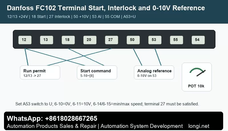
Terminals 12 and 13 provide +24V DC, maximum 200 mA total load. Terminal 20 is the digital input common. In common PNP wiring, terminal 12 or 13 supplies digital input signals.
Terminal 18 is factory set as start through 5-10 = [8] Start. Terminal 27 is factory set as coast stop / external interlock through 5-12. If no external interlock is used, a jumper may be required from terminal 12 or 13 to terminal 27. Otherwise the drive may show auto remote coast or alarm 60.
Terminals 53 and 54 are analog inputs. Terminal 53 is normally used as an open-loop speed reference, while terminal 54 is commonly used as closed-loop feedback. Terminal 55 is analog common. Terminal 50 provides +10V DC, maximum 15 mA, commonly used for a potentiometer.
The analog mode of terminals 53 and 54 depends on hardware switches A53 and A54. U means voltage input; I means current input. Power must be removed before changing the switches.
External Start and Forward/Reverse Control
For FC102, terminal 27 must be handled before terminal 18 start is expected to work. The usual logic is: terminal 27 provides run permission or interlock, and terminal 18 provides the start command.
Basic two-wire start:
1. Wire terminal 12 or 13 through the safety/interlock circuit to terminal 27.
2. Keep 5-12 as coast stop / external interlock, or set it according to the site design.
3. Wire terminal 12 or 13 through the start switch to terminal 18.
4. Set 5-10 = [8] Start.
5. Press Auto On on the LCP.
For reverse operation, first confirm that the fan, pump or machine is mechanically allowed to reverse. If reverse is allowed, assign terminal 19 or 32 as reverse in the 5-1* digital input group and confirm that the motor direction parameter allows both directions.
Test at low frequency without load first. Close terminal 27 permission, then terminal 18 start. Confirm rotation direction, current and airflow/waterflow before increasing speed.
Terminal 53 Potentiometer or 0-10V Reference
The FC102 manual gives a typical open-loop example where terminal 53 receives a 0-10V DC analog control signal. The drive then provides an output frequency proportional to the input signal.
Typical 10k ohm potentiometer wiring:
1. Terminal 50 to one end of the potentiometer.
2. Terminal 55 to the other end as analog common.
3. Terminal 53 to the wiper.
4. Set the A53 switch to U voltage mode.
Recommended parameters:
1. 3-02 Minimum Reference: minimum speed.
2. 3-03 Maximum Reference: maximum speed.
3. 6-10 Terminal 53 Low Voltage: 0V.
4. 6-11 Terminal 53 High Voltage: 10V.
5. 6-14 Terminal 53 Low Reference/Feedback: minimum output frequency.
6. 6-15 Terminal 53 High Reference/Feedback: maximum output frequency.
7. Confirm that terminal 53 is the active speed reference and is not overridden by bus, preset reference or PID control.
If the potentiometer does not work, measure terminal 53 to terminal 55 voltage first. If voltage changes but speed does not, check reference source, Auto On, terminal 18 start, terminal 27 interlock and reference limits.
Common Alarms and Troubleshooting
Warning 1, 10V low: terminal 50 is overloaded or shorted. Disconnect terminal 50 wiring. If the warning disappears, the external wiring is the cause.
Warning/Alarm 2, live zero / wire break: analog input is below 50% of the configured minimum. Check terminals 53/54, terminal 55 common, A53/A54 switches, 6-01 and analog scaling.
Warning/Alarm 4, mains phase loss: check three-phase supply, fuses, contactor and input rectifier.
Warning 5/6, DC link high/low: check mains voltage, load inertia, ramp time and braking.
Alarm 7, DC overvoltage: increase ramp-down time, inspect brake resistor, braking function and trip delay.
Alarm 8, DC undervoltage: check supply voltage, soft-charge fuse, rectifier and 24V backup supply.
Alarm 9, inverter overload: compare LCP output current with rated current and measured motor current. Check load, filters, airflow/waterflow and derating.
Alarm 10, motor ETR overtemperature: check motor load, cooling and motor current parameter.
Alarm 13, overcurrent: check acceleration time, blocked load, motor cable, earth fault and power module.
Alarm 14, earth fault: test motor insulation, cable insulation and terminal box.
Alarm 16, short circuit: check U/V/W wiring, motor winding and output contactor.
Alarm 17, control word timeout: check BMS, RS-485, fieldbus, address, baud rate and timeout function.
Alarm 29, drive overtemperature: check fan, heatsink, filters, ambient temperature and installation clearance.
Alarm 30/31/32, motor phase missing: check output phase, motor cable, contactor and winding.
Alarm 34, fieldbus communication fault: check fieldbus card, cable, termination, master configuration and communication parameters.
Alarm 47, 24V supply fault: check 24V loads, sensors, terminal shorts and control card supply.
Alarm 60, external interlock: check terminal 27, jumper from 12/13, emergency stop, fire interlock and safety circuit.
Alarm 80, drive initialized to default: recheck motor data, terminals, reference source, communication, PID and HVAC application parameters before running.
Practical Commissioning Sequence
Check power wiring, motor insulation, grounding, shielding and control terminals with power off. Confirm terminal 27 interlock or jumper. Power up, set motor data and regional settings in Quick Menu, set reference limits and ramp time, configure terminal 18 start and terminal 27 interlock, configure terminal 53 scaling, press Auto On, test at low frequency, then run under load. After commissioning, upload parameters to the LCP with 0-50.
Conclusion
The FC102 manual becomes practical when the main structure is clear: Status shows live data, Quick Menu handles startup, Main Menu gives full parameter access, Alarm Log stores history, 0-50 backs up and copies parameters, 14-22 initializes, terminals 12/13 provide 24V, terminal 18 starts, terminal 27 is the external interlock, terminal 50 provides 10V, terminal 53 receives 0-10V reference, terminal 55 is analog common, and A53/A54 switches must match the signal type.
For FC102 service work, the three biggest time savers are checking terminal 27 first, verifying terminal 53 scaling, and backing up parameters with 0-50 before changing anything.