The Danfoss VLT Micro Drive FC 51, often called FC51 or FC-051 in the field, is a compact general-purpose AC drive widely used on small fans, pumps, conveyors, packaging machines, textile equipment, auxiliary spindles and retrofit systems. Its manual is not difficult, but service work becomes confusing when the drive mode, terminal logic, analog input mode, password access and reference source are mixed together. For practical maintenance, the most important tasks are clear: use the LCP panel correctly, copy parameters safely, lock and unlock menu access, wire external forward/reverse control, use a 0-10V potentiometer for speed reference, and interpret the fault codes without blindly resetting the drive.
This guide summarizes the FC51 operation manual and programming guide from a commissioning and repair perspective. Parameter numbers are based on the Danfoss FC51 manual structure. Before applying the settings on a machine, always verify the drive nameplate, motor nameplate, supply voltage, emergency-stop circuit, direction limitation and mechanical safety.
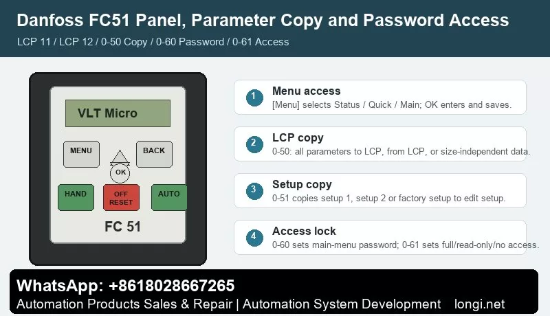
LCP 11 and LCP 12 Panel Operation
FC51 commonly uses two local control panels: LCP 11 without potentiometer and LCP 12 with potentiometer. The panel is divided into four functional areas: digital display, menu key, navigation keys, and operation keys with LED indicators.
The display shows the selected parameter number, parameter value and unit such as Hz, A, V, kW, HP, %, s or RPM. It also indicates motor direction. During troubleshooting, do not look only at the output frequency. Check the active menu, operation mode and direction arrow as well.
The most important key is [Menu]. Pressing it switches between Status Menu, Quick Menu and Main Menu. Status Menu is used for running values. Quick Menu is used for basic commissioning. Main Menu gives access to all parameters.
Quick Menu is suitable for initial setup. Press [Menu] until Quick Menu is selected, press [OK], browse with [Up]/[Down], press [OK] to edit, change the value and press [OK] again to save. Motor power, motor voltage, motor frequency, ramp time and reference limits are normally available there.
Main Menu is required for complete parameter access. Press [Menu] until Main Menu is selected, browse parameter groups with [Up]/[Down], press [OK], select the parameter, edit and save. Digital input settings, analog input settings, password parameters, LCP copying, relay output and communication parameters should be configured from Main Menu.
The operation keys are [Hand On], [Off/Reset] and [Auto On]. Hand On starts the drive locally through the panel. Off/Reset stops the drive and resets alarms. Auto On lets the drive accept control terminals or serial communication. Many "terminal start does not work" cases are simply caused by the drive not being in Auto On.
On LCP 12, the built-in potentiometer has two roles. In Hand mode, it works as the local reference. In Auto mode, it can be used as an additional programmable analog input. Do not confuse the LCP potentiometer with an external potentiometer wired to terminal 53.
Parameter Copying: 0-50 and 0-51
Two FC51 parameters are often confused: 0-50 LCP Copy and 0-51 Setup Copy.
0-50 LCP Copy transfers parameters through the removable LCP panel. Common options are [1] All to LCP, [2] All from LCP, and [3] Size-independent from LCP.
Recommended drive-to-drive copying procedure:
- Stop the source drive and make sure the motor has coasted to stop.
- Enter 0-50 LCP Copy.
- Select [1] All to LCP to upload parameters from the source drive to the panel.
- Move the LCP to the target drive.
- If voltage class, power size and hardware are the same, select [2] All from LCP.
- If the target drive has a different power size, select [3] Size-independent from LCP, then manually verify motor and protection parameters.
The manual states that LCP copying can only be activated from the LCP and only after the motor has coasted to stop. Do not copy parameters while the machine is running. Do not blindly copy all parameters between different power sizes because motor current, overload protection, torque limit, braking and thermal settings may be size-dependent.
0-51 Setup Copy copies setup data inside the same drive. It can copy setup 1, setup 2 or factory setup to the selected edit setup. This is useful when a machine needs two recipes. Tune setup 1 first, copy it to setup 2, then modify only the differences.
Before using 0-51, make sure the motor has coasted to stop and 0-10 Active Setup is set to setup 1 or setup 2. During setup copying, the keypad and parameter database are locked, so do not interrupt power or repeatedly press keys.
Password Locking and Unlocking: 0-60 and 0-61
FC51 "encryption" in field language usually means LCP menu password and access restriction, not a complex authorization system. The key parameters are 0-60 Main Menu Password and 0-61 Access to Main/Quick Menu without Password.
0-60 Main Menu Password sets a password from 0 to 999. 0 means no password. The password applies to LCP access, not to bus communication.
0-61 Access without Password defines what a user can do without the password. The common options are [0] Full access, [1] LCP read only, and [2] LCP no access.
To lock access, set 0-60 to a non-zero password and set 0-61 according to the required protection level. For service records, always write down the password and the reason for locking. A locked drive without documentation wastes repair time.
To unlock access, first confirm that the issue is not simply wrong menu navigation. If a password is required, enter the password, set 0-60 back to 0, and set 0-61 to [0] Full access.
The manual also notes a practical key operation: pressing [Menu], [OK] and [Down] can cancel password locking and bring the panel to a parameter editing screen. Behavior may vary with software version and panel state, so use the actual LCP prompt as the final reference.
External Forward/Reverse Control by Terminals
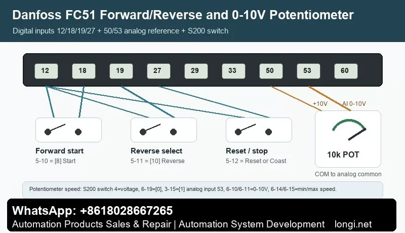
FC51 digital input terminals include 18, 19, 27, 29 and 33. The control card provides terminal 12 as 24V DC output, maximum 200 mA. In factory PNP logic, terminal 12 is commonly used to feed the digital input switches.
The operation manual states that a start signal on terminal 18 and an analog reference on terminal 53 or 60 can make the drive run. Factory assignments are practical: 5-10 terminal 18 digital input = [8] Start, 5-11 terminal 19 digital input = [10] Reverse, and 5-12 terminal 27 digital input = [1] Reset.
A typical forward/reverse wiring scheme is:
- Wire terminal 12 through a forward start switch to terminal 18.
- Set 5-10 = [8] Start.
- Wire terminal 12 through a reverse selection switch to terminal 19.
- Set 5-11 = [10] Reverse.
- Keep terminal 27 as reset, or assign it to coast stop / stop inverse according to the safety circuit.
- Press [Auto On] so the drive accepts terminal commands.
For two separate buttons, one input may be start and another may be start reversing. The digital input option [11] Start reversing starts/stops and reverses at the same time, but it must not be active together with normal start [8]. Interlocking must be designed carefully.
Also check direction limitation. Function [10] Reverse changes direction only; it does not create a start command. The drive must also be configured to allow both directions through the motor direction parameter, commonly 4-10 Motor Speed Direction. If only one direction is allowed, terminal 19 will not reverse the motor.
Terminal logic depends on S200 switches. S200 switch 2 selects PNP/NPN logic for terminals 18, 19, 27 and 33. Factory default is PNP. If wiring appears correct but input status does not change, check this switch. Do not operate the switches while the drive is powered.
External Potentiometer Speed Reference on Terminal 53
FC51 has analog inputs on terminals 53 and 60. Terminal 53 supports 0-10V or 0/4-20mA. Terminal 50 provides 10V DC output, 10.5V +/-0.5V, maximum 25 mA, which is suitable for a small external potentiometer.
Typical 10k ohm potentiometer wiring:
- Terminal 50 to one end of the potentiometer.
- Analog common to the other end.
- Terminal 53 to the wiper.
- The voltage on terminal 53 changes from approximately 0V to 10V as the knob is turned.
Terminal 53 mode is determined by both the S200 switch and parameter 6-19 Terminal 53 Mode. For a 0-10V potentiometer, set S200 switch 4 to voltage mode and set 6-19 = [0] Voltage mode.
Recommended parameters:
- 3-02 Minimum Reference: set the minimum speed.
- 3-03 Maximum Reference: set the maximum speed.
- 3-15 Reference 1 Source: select [1] Analog input 53.
- 6-10 Terminal 53 Low Voltage: normally 0V or near the default low value for 0-10V use.
- 6-11 Terminal 53 High Voltage: 10.00V.
- 6-14 Terminal 53 Low Reference/Feedback Value: normally 0.
- 6-15 Terminal 53 High Reference/Feedback Value: normally 50.00 for a 50 Hz maximum.
- 6-16 Terminal 53 Filter Time Constant: increase only when the signal is noisy.
- Set ramp times so fast knob movement does not cause overcurrent or overvoltage.
If the potentiometer does not work, measure terminal 53 voltage first. If voltage does not change, check terminal 50, potentiometer wiring and analog common. If voltage changes but speed does not, check reference source parameters, Auto On state, start command, min/max reference and communication override.
If fault 2 Live zero / wire break occurs, the manual explains that terminal 53 or 60 signal is below 50% of the configured low limit. For ordinary 0-10V potentiometer use, do not set the low voltage too high unless wire-break detection is intentionally required.
Fault Codes and Troubleshooting
FC51 faults are displayed as numbers. The manual separates warning, alarm and trip-lock conditions. Do not keep pressing reset before identifying the cause.
2 Wire break / live zero: terminal 53 or 60 signal is too low. Check potentiometer, sensor supply, analog common, 6-10, 6-12, 6-22 and 6-01.
4 Mains phase loss: supply phase loss or serious imbalance. Check input voltage, fuses, contactor and terminals.
7 DC link overvoltage: usually caused by too short deceleration, high inertia, brake resistor fault or high mains voltage. Increase ramp-down time and inspect the brake circuit.
8 DC link undervoltage: check mains voltage, contactor drop-out, rectifier and DC bus capacitors.
9 Inverter overload: the drive has carried more than 100% load too long. Check load, acceleration time, cooling and drive sizing.
10 Motor ETR overtemperature: verify motor nameplate parameters, load and cooling at low speed.
11 Motor thermistor overtemperature: check thermistor wiring and actual motor temperature.
12 Torque limit: torque has exceeded 4-16 or 4-17. Check load, ramp time and torque limit settings.
13 Overcurrent: check motor cable, output short circuit, earth leakage, blocked load and power module. Do not repeatedly reset.
14 Earth fault: disconnect power and test motor insulation, cable insulation and output wiring.
16 Short circuit: inspect U/V/W phase-to-phase short circuit, motor terminal box and inverter output stage.
17 Control word timeout: check serial communication, address, baud rate, control word and bus master.
25 Brake resistor short / 27 Brake chopper short / 28 Brake check: inspect resistor value, wiring, insulation and brake transistor.
29 Power card temperature: check fan, heatsink dust, ambient temperature, installation spacing and overload.
30/31/32 Motor phase U/V/W missing: check the corresponding output phase, motor cable and motor winding.
38 Internal fault: record the exact condition and inspect control board, power supply, power card and parameter memory.
47 Control voltage fault: 24V DC may be overloaded. Check terminal 12 loads, external sensors and digital input wiring.
51/52 AMT faults: motor voltage/current data may be wrong or motor current too low. Check nameplate parameters and output connection.
59 Current limit: check load, acceleration time, torque limit and motor data.
63 Mechanical brake low: actual motor current did not exceed the brake release current during start delay. Check brake logic and mechanical brake.
80 Drive initialized: parameters have returned to default values. Recheck motor data, terminals, reference source, communication and protection settings before running.
Practical Commissioning Sequence
For a new installation, replacement or repair, use this order:
- Check power wiring, motor insulation, earthing and control wiring with power off.
- Power up and verify that Main Menu access works.
- Set motor nameplate data.
- Set 3-02 and 3-03 reference limits.
- Set ramp-up and ramp-down times.
- Configure terminals 18, 19 and 27.
- Configure terminal 53 with 6-19, 6-10, 6-11, 6-14 and 6-15.
- Test forward, reverse and potentiometer speed at low frequency without load.
- Run with load and monitor frequency, motor current, temperature and alarms.
- Back up parameters with 0-50, then apply 0-60/0-61 only if access protection is required.
Conclusion
The FC51 manual becomes straightforward when the main structure is clear: [Menu] switches between Status, Quick and Main menus; [OK] edits and saves; Hand On is local control; Auto On is terminal or communication control; 0-50 copies parameters through LCP; 0-51 copies internal setups; 0-60 sets the main-menu password; 0-61 sets no-password access; terminal 18 is start; terminal 19 is reverse; terminal 27 is reset by default; terminal 53 is the main analog input for 0-10V speed reference; and fault codes should be diagnosed by supply, load, motor, terminal, cooling and communication sequence.
Most FC51 field problems come from mixed control modes, wrong PNP/NPN switch position, wrong voltage/current mode on terminal 53, locked menu access or incorrect reference source. Separate these items one by one, and the FC51 is a very manageable drive to commission and repair.