
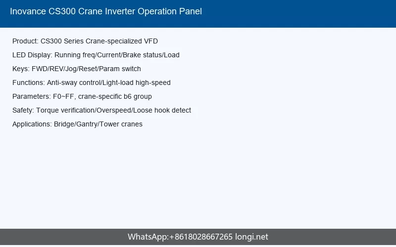
Inovance CS300 Series Crane-specialized Inverter User Guide: Operation Panel, Terminal Control and Fault Troubleshooting
1. Introduction
The Inovance CS300 series is a dedicated crane-specialized variable frequency inverter (VFD) developed by Inovance Technology specifically for the lifting industry. Designed with a compact form factor, small power footprint, and high cost-performance ratio, the CS300 addresses the demanding requirements of hoisting, trolleying, slewing, and traversing applications found in small-to-medium lifting equipment. This inverter is engineered to drive asynchronous induction motors with exceptional starting torque and precise speed control, making it an ideal choice for overhead cranes, gantry cranes, jib cranes, and material handling systems where safety and reliability are paramount.
The CS300 supports two primary control modes: sensorless vector control (open-loop) and V/F control. In open-loop vector mode, the drive delivers a starting torque of 200% at 0.5 Hz, enabling confident load lifting even from a standstill. The V/F mode provides 150% starting torque at the same frequency, suitable for less demanding traverse and slew mechanisms. With a speed regulation range of 1:100 in vector mode and 1:50 in V/F mode, operators gain fine-grained control over crane motions. The steady-speed accuracy is rated at ±0.5% for open-loop vector and ±1% for V/F control, ensuring smooth travel and minimal load swing.
A defining characteristic of the CS300 is its built-in crane-specific functionality. Unlike general-purpose inverters, the CS300 incorporates professional brake control logic (抱闸控制) tailored to lifting mechanisms. The integrated brake timing sequence manages electromagnetic brake engagement and release with programmable delay parameters, effectively preventing load slippage—commonly known as “hook glide” or “溜钩”—during start and stop transitions. This anti-sway behavior is critical in crane operations where suspended loads must not oscillate dangerously.
The overload capacity is robust: 120% rated current for one hour, 150% for one minute, and 180% for two seconds. Such ratings accommodate the intermittent duty cycles and shock loads typical in lifting applications. The torque boost function offers both automatic and manual compensation (0.1% to 30.0%), ensuring adequate low-frequency torque when lifting heavy payloads at reduced speeds. Additional crane-oriented features include light-load high-speed operation (弱磁增速), shaft-cooled motor low-speed protection, and a built-in gearbox utilization calculator to assist with predictive maintenance.
The product range spans from 0.4 kW to 18.5 kW, all operating on three-phase 380 V to 440 V supplies (±15% to +10% voltage tolerance). Every unit includes an internal braking chopper, eliminating the need for external brake modules in most configurations. The CS300 carries CE certification, conforming to the Low Voltage Directive (LVD) and EMC Directive, specifically meeting EN 61800-3, EN 55011, EN 61000-6-2, and EN 61800-5-1 standards. The enclosure rating is IP20 with pollution degree PD2, suitable for installation inside control cabinets away from direct exposure to moisture, dust, and corrosive gases.
2. Operation Panel
2.1 Panel Overview and Indicators
The CS300 is equipped with a standard LED keypad (also referred to as the LED operator or operation panel) that serves as the primary human-machine interface. The panel provides a five-digit seven-segment LED display capable of showing set frequencies, output frequencies, monitor data, alarm codes, and parameter addresses. Surrounding the display are four status indicators that communicate the inverter’s operating state at a glance.
The FWD/REV indicator denotes motor direction: extinguished for forward rotation and illuminated for reverse rotation. The REMOT indicator distinguishes command source—off signifies keypad control mode (LOCAL), while on indicates terminal control mode (REMOTE). The dual-color RUN/ERR lamp delivers critical status information: off when stopped, green when running, and red when a fault is active. The TUNE/TC indicator illuminates during motor auto-tuning procedures and remains off during normal operation.
2.2 Keypad Buttons and Navigation
The keypad layout includes eight functional buttons. The PRG (Program) key enters or exits the first-level menu. The ENTER key confirms parameter selections and steps deeper into sub-menus. The UP and DOWN arrow keys increment or decrement data values and scroll through parameter lists. The SHIFT key cycles through display parameters during idle or run states and selects the digit to modify when editing values. The RUN key initiates motor operation when the keypad is configured as the command source. The STOP/RESET key halts the drive during operation and resets active faults when in alarm state. A dedicated QUICK key provides rapid access to the password entry interface.
2.3 Menu Structure and Parameter Editing
The CS300 organizes parameters into a three-tier menu hierarchy designed to match user expertise. The first-level menu (Group A) contains basic crane parameters and brake timing adjustments—sufficient for most commissioning tasks. The second-level menu (Groups b, E, and U) exposes intermediate functions such as motor control, I/O configuration, ramp settings, multi-speed tables, and monitor data. The third-level menu (Group F) houses advanced performance tuning parameters including vector control PI gains, motor electrical constants, and PWM optimization settings. Each level is protected by independent passwords (AF.00, bF.00, FF.00), preventing unauthorized modifications.
To edit a parameter, press PRG to enter the menu, use the arrow keys to locate the desired function code (for example, b1.02 for maximum frequency), press ENTER to access the value, adjust with UP/DOWN and SHIFT, then press ENTER again to save. If the display shows no flashing digit, the parameter is either read-only (such as monitor values) or cannot be modified while the inverter is running. Parameters must generally be changed in the stopped state.
2.4 Monitoring and Status Display
During operation or standby, the user can cycle through real-time data using the SHIFT key. In run mode, the display can show set frequency, output (feedback) frequency, output current, output voltage, and DC bus voltage. In stop mode, target frequency and bus voltage are available. For commissioning and troubleshooting, the U0 group provides live data including output torque, inverter temperature, DI/DO status, and internal state codes that reveal whether the drive is in standby, brake-releasing, normal run, or brake-closing phases.
3. Terminal Control
3.1 Control Terminal Layout
The CS300 control circuit provides six digital input terminals (DI1 through DI6) and two relay output terminals (T1A-T1C and T2A-T2C), along with a +24 V DC power supply and a common terminal (COM). The digital inputs are opto-isolated and uniquely compatible with both AC and DC signals, accepting voltages from 15 V DC to 56 V DC, or 10 V AC to 54 V AC. This dual compatibility allows seamless integration with existing crane control circuits that may use 24 V DC, 36 V DC, 48 V DC, or even 36/48 V AC control transformers.
An external power input terminal (OP) is provided for flexibility. In the default factory configuration, OP is jumpered to the internal +24 V supply. When an external control voltage is used, the internal jumper must be removed and the external positive (for sinking/NPN inputs) or negative (for sourcing/PNP inputs) connected to OP, depending on the wiring topology selected.
3.2 Digital Input Functions for Crane Applications
Each DI terminal can be assigned one of numerous functions via parameters b3.01 through b3.06. For a typical two-wire crane control scheme, the following assignments are standard:
- DI1 (b3.01 = 1): Forward run (hoist up / trolley forward)
- DI2 (b3.02 = 2): Reverse run (hoist down / trolley reverse)
- DI3 (b3.03 = 8): Multi-speed select bit 1
- DI4 (b3.04 = 9): Multi-speed select bit 2
- DI5 (b3.05 = 3): Fault reset
- DI6 (b3.06 = 5): Free stop / external emergency stop
Additional functions critical to cranes include jog forward (17), jog reverse (18), acceleration (19), deceleration (20), forward/reverse stop switches (22/23), and forward/reverse slowdown switches (24/25) for simple positioning. The crane mechanism type selection (parameter A0.08) automatically optimizes associated parameters for hoisting (0), traversing (1), or slewing (2) when changed.
3.3 Relay Output Configuration
The two relay outputs are configured through b3.14 and b3.15. Each relay can switch up to 250 V AC at 3 A (cos φ = 0.4) or 30 V DC at 1 A. For crane duty, the recommended assignments are:
- Relay 1 (T1A-T1C, b3.14 = 1): Brake control output. This is the most important crane-specific function. When the inverter determines that motor torque is sufficient to hold the load, the relay energizes to release the mechanical brake. During stopping, once frequency drops below the holding threshold, the relay de-energizes to set the brake.
- Relay 2 (T2A-T2C, b3.15 = 2): Fault stop output. This drives a safety contactor (KM) that disconnects the control circuit or triggers an external alarm whenever a Level-1 fault occurs.
The brake control output timing is fully programmable via the b6 parameter group, as detailed in the Parameter Settings section.
3.4 Wiring Practices and Safety
When wiring control terminals, maintain separation between power cables and signal cables. Use shielded twisted-pair cables for control wiring and ground the shield at one end only to avoid ground loops. The DI inputs include a software filter time (b3.21, default 0.010 s) that suppresses contact bounce from mechanical limit switches and pushbuttons; increase this value if intermittent false triggers occur in electrically noisy crane environments.
Never use input-side contactors to start and stop the inverter, as repeated charging cycles degrade the internal DC bus capacitors. If an input contactor is installed for isolation, operate it no more than once per hour during normal crane duty.
4. Parameter Settings
4.1 First-Level Menu (Group A) — Crane Basics
The A-group parameters define the fundamental crane and motor characteristics. Begin commissioning by entering the motor nameplate data: A0.01 (rated power), A0.02 (rated voltage), A0.03 (rated current), A0.04 (rated frequency, typically 50 Hz), and A0.05 (rated speed, typically around 1400 rpm for a 4-pole motor). Accurate entry of these values is essential because the vector control algorithm depends on them to calculate torque-producing current.
Parameter A0.07 selects the frequency command source. For most crane pendants and cabin controls, set A0.07 = 0 for multi-speed operation. This allows up to eight preset speeds selected by binary combinations of three DI inputs (functions 8, 9, 10). Alternatively, A0.07 = 4 enables acceleration/deceleration control via momentary UP/DOWN pushbuttons (functions 19 and 20), suitable for stepless speed command from master switches.
Parameter A0.08 is unique to the CS300: the crane mechanism selector. Setting this to 0 (hoisting) automatically adjusts control mode to sensorless vector, sets brake release current to 30.0%, enables load-overspeed faults (37# and 38#), and sets speed-loop gain to 60. Setting it to 1 (traversing) switches to V/F control, disables certain hoist-specific faults, and reduces speed-loop gain to 30. This single parameter dramatically simplifies commissioning by auto-configuring dozens of related settings.
4.2 Brake Timing Control (Group b6) — Anti-Sway and Hook Stability
The b6 group contains the heart of the CS300’s crane specialization: the brake sequence control. This is where the anti-sway and load stability performance is tuned. Parameter b6.00 selects the brake curve type:
- 0: No brake control (output function 1 acts as simple “inverter running” signal).
- 1: Automatic brake control. During the brake release interval, the inverter automatically builds current up to the threshold defined by
b6.03before commanding the brake to open. - 2: Manual brake control. Similar to automatic, but uses dedicated torque limits (
b1.06andb1.07) during the release phase for finer tuning. - 3: Conical motor control. A special mode for cone brake motors where the brake is integral to the motor.
The key timing parameters are:
b6.02— Brake release frequency (default 2.00 Hz): the frequency held while the mechanical brake is opening. Must be high enough that the motor can generate full holding torque, yet low enough to prevent sudden load lurch.b6.03— Brake release current (default 30.0% of rated current): the output current threshold that must be reached before the brake release command is issued. For hoisting, 30% is typical; for traversing, 0% may be used.b6.04— Brake release time (default 0.50 s): the mechanical delay from brake energization to full release. Set this slightly longer than the actual mechanical delay to prevent hook glide.b6.05— Brake apply frequency (default 2.00 Hz): when stopping, once output frequency falls below this value, the brake close command is issued.b6.06— Brake apply time (default 0.50 s): the mechanical delay for the brake to fully close. During this interval the inverter holdsb6.05frequency.
Proper tuning of these six parameters ensures that the load is held by motor torque before the mechanical brake opens, and that the brake is fully engaged before motor torque is removed. This eliminates the frightening “drop and catch” behavior that causes load sway and mechanical shock.
4.3 Second-Level Menu (Group b) — Motion Profiles and Limits
The b-group covers ramp profiles, multi-speed tables, I/O assignments, and protective functions. Parameters b4.00 and b4.01 set acceleration and deceleration times from zero to rated frequency. For crane hoisting, conservative ramps (3.0 s to 10.0 s) are typical to avoid shock; trolley and slew drives may use shorter ramps. S-curve ramps (b4.02 = 1) provide gentler starts and stops, highly desirable for minimizing pendulum swing in suspended loads.
Multi-speed frequencies are stored in b5.00 through b5.07. A common four-speed crane pendant might use 5 Hz (creep), 20 Hz (low), 35 Hz (medium), and 50 Hz (high). The binary combination of three DI inputs selects among these. Parameter b1.02 defines the maximum frequency (up to 150 Hz); for standard 50 Hz motors, leave this at 50.00 Hz unless overspeed is intentionally required.
Torque limits are set in b1.04 (forward) and b1.05 (reverse), defaulting to 180.0%. For hoisting, the forward direction is usually “up,” so a high limit prevents stalling. The reverse direction (“down”) may be limited to a lower value if controlled lowering is desired. The light-load high-speed feature (Group b7) can automatically raise operating frequency above rated when the load is light, improving cycle times without risk of overload.
4.4 Third-Level Menu (Group F) — Performance Tuning
The F-group is password-protected (FF.00) and intended for advanced users. It includes motor electrical parameters (F0.00 to F0.04) obtained through auto-tuning, vector speed-loop PI gains (F1.00 to F1.04), and V/F control options (F2.01 torque boost, F2.11 oscillation suppression). If the crane exhibits motor oscillation or hunting at low speeds, reduce the speed-loop proportional gain (F1.00) or increase the integral time (F1.01). If the drive trips on over-voltage during rapid lowering of light loads, increase the over-excitation gain (F1.07).
5. Communication
The CS300 series is designed primarily as a standalone, terminal-controlled drive for crane applications where simplicity and rugged reliability take precedence over networked control. As of firmware version C07 (November 2021 release), communication expansion options—including CANlink and multi-function I/O expansion cards—have been removed from the product documentation. The current hardware platform does not support fieldbus communication modules, and users should plan their control architecture accordingly.
For most crane installations, this absence of communication capability is not a limitation. Crane control traditionally relies on hardwired pushbuttons, pendant stations, and cam-type master switches that interface directly with the DI terminals. The six digital inputs and two relay outputs provide sufficient I/O for two-speed or multi-speed pendant control, emergency stop circuits, limit switches, and brake feedback. Hardwired control is inherently more immune to electromagnetic interference—a significant advantage in the electrically noisy environment of steel mills, ports, and heavy industrial plants where large cranes operate.
Where centralized PLC or DCS integration is required, consider using the PLC’s digital output modules to drive the CS300 DI terminals, and read the CS300 relay outputs back into digital input modules. This preserves the deterministic response and safety integrity required for crane safety circuits. If serial communication is mandatory for the overall machine design, a separate communication-enabled VFD from Inovance’s broader portfolio may be evaluated for non-critical axes, while retaining the CS300 for the safety-critical hoist axis.
6. Fault Codes
6.1 Fault Severity Classification
The CS300 classifies faults into five levels based on their impact on the crane system. Understanding these levels is essential for designing safe fault response logic in the control cabinet.
- Level 1 (Er1**): Critical faults. The inverter immediately disables the brake control output, activates the fault-stop relay (output function 2), and executes a free stop. The load is held by the mechanical brake. Examples include overcurrent, overvoltage, module overheat, and ground short.
- Level 2 (Er2**): Serious faults. The fault-alarm relay (output function 3) activates, and the inverter performs a fast stop (ramping to brake-apply frequency then stopping). The brake timing sequence is respected.
- Level 3 (Er3**): Moderate faults. Similar to Level 2 but the inverter decelerates along the normal ramp time.
- Level 4 (Er4**): Minor faults. The fault-prompt relay (output function 4) activates, but operation continues. These serve as warnings for the operator or maintenance team.
- Level 5: Information only. No display or output action; the fault is logged internally for diagnostics.
Fault codes 01# through 40# are drive-performance faults and are fixed at Level 1. Codes 41# through 65# are functional faults (brake feedback, simultaneous run commands, etc.) whose levels can be customized via parameters bF.10 through bF.14. Codes 66# and above are application-level faults handled by optional process cards.
6.2 Common Drive Faults and Remedies
02# — Acceleration Overcurrent: Occurs when output current exceeds limits during ramp-up. Likely causes include shorted motor cables, missing motor parameter identification, overly aggressive acceleration time, excessive manual torque boost, low supply voltage, or attempting to start a spinning load. Remedies: check motor and cable insulation with a 500 V megohmmeter; perform motor auto-tuning (b0.04 = 2 or 3); increase b4.00; reduce torque boost; ensure adequate supply voltage; or enable spin-start if applicable.
03# / 04# — Deceleration or Constant-Speed Overcurrent: Similar root causes to 02#, but during ramp-down or steady run. If lowering heavy loads causes 03#, verify that the internal braking chopper is functional and that an appropriately sized braking resistor is connected between P(+) and BR terminals. The resistor cable should not exceed 5 meters.
05# / 06# / 07# — Overvoltage: Generated when the DC bus exceeds safe thresholds. This is especially common during regenerative lowering if the braking resistor is undersized or missing. Confirm resistor wattage and ohms match the selection tables in the manual. Also extend deceleration times or add an output reactor if motor cable capacitance is high.
09# — Undervoltage: Indicates the DC bus has fallen below the trip threshold. Check for momentary power dips, poor input connections, or an undersized supply transformer. Parameter F3.06 can adjust the undervoltage trip point within a 60% to 140% range.
10# — Inverter Overload: The drive has experienced sustained current above its thermal limit. Verify the crane is not overloaded beyond rated capacity, that the motor is not mechanically jammed, and that the VFD is adequately sized for the duty cycle.
11# — Motor Overload: The motor thermal model has tripped. Confirm that parameter bE.01 (motor overload gain) is correctly set to match the motor’s actual overload capability. The default of 1.00 assumes standard service factor; reduce this value if the motor has a lower thermal margin.
14# — Module Overheat (Er114): The IGBT heatsink temperature is too high. Causes include blocked ventilation, failed cooling fan, excessive carrier frequency, or ambient temperature above 40°C. Clean air ducts, replace the fan if bearing noise or slow rotation is evident, and reduce carrier frequency (F0.16) if necessary. Note that fans have a typical service life of 2–3 years in continuous crane duty.
6.3 Crane-Specific Functional Faults
37# — Frequency Direction Abnormal: The motor feedback frequency direction is opposite to the commanded direction for longer than bC.02 (default 0.50 s). In hoisting, this can happen if the load is so heavy that the motor cannot hold it, or if motor phase wiring is reversed. Check mechanical loading and verify U-V-W connections.
38# — Frequency Follow Error: The difference between commanded and feedback frequency exceeds bC.03 (20% of rated) for longer than bC.04 (0.50 s). This suggests severe load slip, encoder issues (if equipped), or incorrect motor parameters. Check load conditions and motor nameplate data accuracy.
40# — Cycle-by-Cycle Current Limit: The fast current limiter has been active too long. The load may be mechanically jammed, or the inverter is undersized. Reduce load or select a larger VFD.
41# / 42# — Brake Release / Brake Apply Fault: These indicate the brake feedback contacts did not confirm the expected state within the configured detection window. Parameter b6.08 defines whether feedback is used: 0 = no feedback, 1 = check only during transitions, 2 = continuous monitoring. If these faults appear, inspect brake coil wiring, verify contactor operation, and ensure DI inputs 11 and 12 are correctly wired to the brake auxiliary contacts.
43# — Shaft-Cooled Motor Low-Speed Timeout: A protection for motors whose cooling fan is shaft-mounted. When operating below b0.00 (default 5.00 Hz) for longer than b0.01, the drive trips to prevent motor overheating. If low-speed operation is required, increase b0.01 or add a forced ventilation fan.
44# — Forward/Reverse Command Simultaneous: Both direction commands are active. Check pendant wiring for shorted contacts or stuck relays.
50# — External Input Fault: Triggered when DI function 6 (external fault input) becomes active. This is typically wired to thermal switches, overload relays, or crane safety limit switches.
6.4 Fault Record and Diagnostics
The CS300 retains the last sixteen fault events in the E* groups (E0 = most recent, EF = oldest). Each record stores the fault code, output frequency, target frequency, output current, voltage, power, torque, bus voltage, and the state of all digital inputs and outputs at the moment of trip. This data is invaluable for post-incident analysis. To clear the history, use bF.03 = 1.