
In new energy vehicle maintenance, complaints such as “the air conditioner is not cooling,” “the compressor makes no sound,” or “the diagnostic tester shows an A/C-related fault” are very common. In particular, when servicing BYD electric vehicles equipped with high-voltage electric air-conditioning compressors, many technicians still use the diagnostic habits developed from conventional gasoline vehicles: once the A/C does not work, they immediately suspect the compressor and may even recommend replacing the entire compressor assembly.
This approach is risky and often incorrect.
A new energy vehicle A/C compressor is not a conventional belt-driven mechanical compressor. It is a high-voltage electric device supplied by the traction battery, usually integrating an electric motor, inverter drive circuit, control electronics, protection circuits, and communication functions. Whether the compressor can run does not depend only on the compressor itself. It also depends on high-voltage system status, vehicle control permissions, battery management system conditions, refrigerant pressure, temperature sensors, A/C controller commands, CAN communication, and high-voltage interlock circuits.
Therefore, when diagnosing a BYD electric vehicle with suspected A/C compressor failure, the correct principle is:
Confirm whether the compressor has all required operating conditions before concluding that the compressor itself is defective.
A compressor should never be replaced simply because the A/C is not cooling, the compressor appears not to run, or a diagnostic screen shows an abnormal condition.
This article explains the structure, working logic, fault diagnosis process, key data parameters, and common misdiagnoses associated with BYD high-voltage electric A/C compressors. It is intended as a practical technical reference for electric vehicle service technicians, automotive repair workshops, and maintenance professionals.
1. Identifying the Component: This Is Not a Conventional Compressor
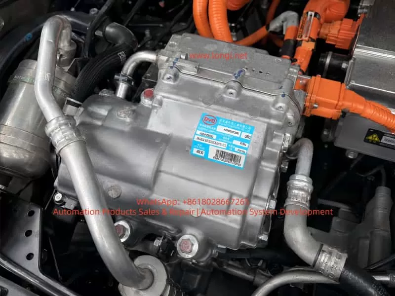
The nameplate on the component provides several important details:
- Manufacturer: BYD Auto Industry Co., Ltd.
- Description: Electric Compressor Assembly
- Refrigerant: R134a
- Rated operating voltage: approximately 408.8 V
- Compressor model: HDE-8103020D
- Compressor assembly identification code: ACE66D or similar, depending on the exact label marking
The most important markings are “Electric Compressor Assembly” and “408.8 V.”
These markings confirm that the component is part of the vehicle high-voltage thermal management system. Unlike a traditional engine-driven compressor, it is powered directly by the traction battery through the high-voltage system. The internal inverter converts high-voltage DC power into three-phase AC power to drive the compressor motor.
A high-voltage electric A/C compressor can generally be considered a combination of the following sections:
- Compressor mechanical body
- Three-phase permanent magnet motor
- Internal inverter drive module
- Electronic control board
- Rotor position or speed detection circuit
- High-voltage DC input section
- Low-voltage communication and control connector
- Internal temperature protection circuit
- Insulation monitoring-related structure
- Refrigerant compression and lubrication system
For this reason, the traditional gasoline vehicle inspection method of “checking whether the 12 V compressor clutch engages” does not apply to electric vehicles.
Most high-voltage electric compressors do not use conventional electromagnetic clutches. Their operation depends on whether the vehicle control system issues a speed command, whether high-voltage power is available, whether safety conditions are satisfied, and whether the compressor itself has internal electrical or mechanical faults.
2. Fundamental Differences Between EV and Conventional Vehicle A/C Systems
The operating logic of a conventional gasoline vehicle A/C system is relatively simple:
Engine running
→ Engine belt drives compressor
→ Electromagnetic clutch engages
→ Compressor circulates refrigerant
→ Evaporator produces cooling.
The logic of an electric vehicle A/C system is much more complex:
Traction battery high-voltage system powers on
→ BMS confirms battery status is acceptable
→ High-voltage contactors close
→ VCU confirms the vehicle is in an allowed operating condition
→ A/C controller receives a cooling request
→ System checks cabin temperature, ambient temperature, evaporator temperature, refrigerant pressure, and other conditions
→ A target compressor speed command is sent through CAN communication
→ Compressor verifies high-voltage supply, communication status, and internal conditions
→ Internal inverter drives the electric motor
→ Compressor circulates refrigerant and produces cooling.
This process shows that a compressor may fail to operate for many reasons other than compressor damage.
The main categories include:
- No A/C request or no compressor command
- High-voltage system not powered up correctly
- Compressor communication failure
- Refrigerant system conditions not satisfied
- Internal compressor electronic or mechanical fault
- Vehicle protection strategy disabling compressor operation
Therefore:
No cooling does not automatically mean the compressor has failed.
Compressor not running does not automatically mean the compressor assembly is defective.
3. Common Incorrect Judgments During Diagnosis
Several mistakes are frequently made when diagnosing high-voltage electric compressor faults.
3.1 No Audible Compressor Noise Means the Compressor Is Bad
This is not reliable.
Electric compressors can be very quiet, especially at low speed. In a noisy workshop environment, with cooling fans operating or with underbody insulation installed, it may be difficult to hear compressor operation from outside the vehicle.
The correct approach is to use a diagnostic tool and inspect live data such as:
- A/C request status
- Compressor enable status
- Compressor target speed
- Compressor actual speed
- Compressor operating status
- Compressor fault level
- High-voltage bus voltage
- Refrigerant pressure
- Evaporator temperature
- Compressor current or power consumption
If the target speed is commanded but actual speed remains zero, then the technician can begin to suspect the compressor, high-voltage supply, or communication circuit.
3.2 A/C Not Cooling Means Refrigerant Must Be Added or Compressor Must Be Replaced
This is another common mistake.
In an electric vehicle, low refrigerant charge, excessive refrigerant charge, refrigerant leakage, pressure sensor failure, electronic expansion valve malfunction, or poor condenser cooling can all prevent the compressor from operating.
For example:
- If refrigerant pressure is too low, the system may assume leakage and disable the compressor.
- If refrigerant pressure is too high, the system may enter overpressure protection.
- If the evaporator temperature is too low, the controller may stop the compressor to prevent icing.
- If the condenser fan is not working, high-side pressure may rise and trigger shutdown.
- If the pressure sensor signal is unreliable, the controller may refuse to enable the compressor.
Therefore, adding refrigerant or replacing the compressor without checking pressure data and fault codes is not a professional diagnostic method.
3.3 Measuring High Voltage Directly at the Compressor Without Proper Procedure
This is dangerous.
The compressor label indicates an operating voltage around 408.8 V. The high-voltage input circuit may therefore carry several hundred volts DC. Improper disconnection of high-voltage connectors, careless measurement with an unsuitable multimeter, or failure to follow the correct high-voltage isolation procedure can result in electric shock, arcing, short circuits, or damage to the vehicle control system.
Before servicing a high-voltage compressor, technicians must follow the manufacturer-approved high-voltage shutdown procedure. This generally includes isolating high-voltage power, waiting for capacitor discharge, confirming absence of voltage, and using proper insulated safety equipment.
3.4 Diagnostic Tool Shows “Normal,” So the Compressor Must Be Good
This conclusion is also unreliable.
A diagnostic tool showing “normal” may only indicate that a control module has not reported a specific active fault or that communication with the module is currently available.
It does not necessarily prove that:
- The compressor mechanical section is healthy.
- The internal inverter is functioning correctly under load.
- The compressor can run normally at commanded speed.
- Refrigeration performance is normal.
- The refrigerant circuit is operating correctly.
For example, a compressor may pass its static self-check but fail when it receives a high-speed command due to overcurrent, mechanical seizure, overheating, insulation issues, or internal inverter faults.
For this reason, fault codes, live data, dynamic operation, refrigerant pressure changes, and actual cooling performance must all be evaluated together.
4. Required Operating Conditions for a High-Voltage Electric Compressor
The most effective way to diagnose whether a high-voltage compressor should operate is not immediate disassembly. Instead, the technician should establish whether all operating conditions are present.
A typical high-voltage electric compressor requires the following conditions.
4.1 Vehicle High-Voltage System Must Be Active
The vehicle must successfully enter READY mode or complete its high-voltage power-up process.
If the traction battery contactors are not closed and the high-voltage bus is not established, the compressor cannot receive the required DC voltage and cannot operate.
Relevant checks include:
- Can the vehicle enter READY mode normally?
- Is there any traction system warning light?
- Is there any insulation fault in the high-voltage system?
- Are the high-voltage contactors closing correctly?
- Does the BMS report any fault preventing high-voltage activation?
- Is the service disconnect correctly installed?
- Is the high-voltage interlock circuit intact?
4.2 The A/C Controller Must Issue a Cooling Request
Pressing the A/C button does not always mean the compressor must start immediately.
The controller may evaluate:
- Ambient temperature
- Cabin temperature
- Requested set temperature
- Evaporator temperature
- Defrost requirements
- Battery thermal management demand
- Energy-saving strategy
- Battery state of charge
- Battery temperature
- Vehicle operating mode
- Communication status between A/C-related control units
For example, in cold ambient conditions, the compressor may not start immediately even when the A/C button is pressed. On the other hand, the compressor may run for battery thermal management even if the cabin cooling demand is low.
4.3 High-Voltage Supply Must Be Normal
The compressor requires stable high-voltage DC input.
The following items should be checked:
- High-voltage bus voltage
- Compressor high-voltage fuse
- High-voltage connector condition
- High-voltage cable damage
- High-voltage power distribution output
- High-voltage interlock circuit
- Connector locking condition
- Terminal corrosion, overheating, or looseness
It is important to understand that a high-voltage supply fault does not always mean complete loss of voltage. A loose connector, partially burnt terminal, or damaged cable may appear acceptable under no-load conditions. However, when compressor current rises during startup, voltage may collapse and trigger compressor protection.
4.4 CAN Communication Must Be Normal
In many electric vehicles, the compressor receives operating commands through CAN communication.
Relevant modules may include:
- Vehicle Control Unit, VCU
- Battery Management System, BMS
- Air-conditioning controller
- Thermal management controller
- Battery thermal management controller
- Electric compressor controller
- DC-DC converter
- PTC heater controller
- Gateway module
If compressor CAN communication is abnormal, the following symptoms may occur:
- A/C panel operates normally, but compressor does not start.
- The display shows A/C enabled, but no cold air is produced.
- Compressor communication fault codes are present.
- Compressor target speed remains zero.
- Diagnostic tester cannot access compressor live data.
- Other high-voltage systems appear normal while thermal management functions fail.
4.5 Refrigerant System Pressure Must Be Within Normal Range
An electric compressor is not allowed to run under every condition simply because high voltage is present.
Many EVs use refrigerant pressure data to determine whether compressor operation is safe. If refrigerant pressure is too low, too high, unstable, or implausible, the controller may limit or stop compressor operation.
Typical issues include:
- Refrigerant leakage causing low pressure
- Incorrect refrigerant charge after repair
- Condenser blockage or poor airflow
- Electronic expansion valve sticking
- Receiver-drier blockage
- Pressure sensor drift
- Damaged or crushed refrigerant pipes
- Air or moisture contamination in the system
- Incorrect compressor oil type
Electric compressors require refrigeration oil with suitable electrical insulation properties. Using incorrect oil, mixing conventional compressor oil, or contaminating the system with unsuitable service equipment can reduce insulation resistance and potentially cause electrical or internal compressor damage.
4.6 Compressor Internal Condition Must Be Normal
Only after all external operating conditions have been confirmed should the compressor itself become the primary suspect.
Internal compressor faults may include:
- IGBT or MOSFET failure
- DC bus capacitor failure
- Drive board failure
- Control chip failure
- Motor winding short circuit, open circuit, or turn-to-turn fault
- Rotor seizure
- Scroll mechanism damage
- Bearing damage
- Internal temperature sensor fault
- Rotor position sensor fault
- Seal failure causing refrigerant or oil contamination
- Insulation resistance failure
- Water ingress or corrosion in electronic circuits
These faults are genuine compressor assembly faults.
5. Using Diagnostic Live Data to Determine Compressor Failure
The most valuable step in electric compressor diagnosis is reading complete live data before removing parts.
The following parameters should be checked whenever available:
| Parameter | Normal Diagnostic Direction | Possible Fault Direction |
|---|---|---|
| A/C request status | Request active | A/C panel, controller, communication issue |
| Compressor enable status | Allowed to run | Protection condition or system restriction |
| Compressor target speed | Target RPM present | Controller not commanding compressor |
| Compressor actual speed | Should follow target RPM | Compressor, power supply, communication, protection |
| Compressor status | Normal operation | Internal fault or disabled status |
| High-voltage bus voltage | Within normal HV range | Battery, contactor, fuse, wiring issue |
| Compressor current | Should change after startup | No startup, internal fault, supply problem |
| Refrigerant pressure | Within operating range | Refrigerant, sensor, fan, blockage issue |
| Evaporator temperature | Should decrease during cooling | Cooling performance or sensor issue |
| Condenser fan status | Should operate when required | Fan, relay, controller issue |
| Battery temperature | Within acceptable range | Thermal management or power limitation |
| Compressor fault code | No active compressor fault | Use code to guide diagnosis |
The most important diagnostic logic is described below.
Condition A: Compressor Target Speed Is Zero
This means the vehicle is not requesting compressor operation.
In this case, do not suspect the compressor first. Check:
- Is the A/C request active?
- Does the A/C controller permit cooling?
- Is ambient temperature appropriate?
- Is cabin temperature above the set value?
- Is refrigerant pressure normal?
- Is evaporator temperature too low?
- Is the BMS limiting power?
- Is there a high-voltage or thermal management fault?
- Is CAN communication normal?
Condition B: Compressor Target Speed Exists but Actual Speed Remains Zero
This condition is highly important.
It means the vehicle has commanded the compressor to operate, but the compressor has not successfully started.
The technician should focus on:
- Compressor high-voltage supply
- High-voltage fuse
- High-voltage connector
- High-voltage interlock circuit
- Compressor CAN communication
- Compressor internal fault codes
- Compressor temperature
- Compressor mechanical seizure
- Compressor insulation status
If high voltage, CAN communication, control command, and refrigerant conditions are all normal, but the compressor still cannot establish actual speed, the probability of internal compressor failure becomes high.
Condition C: Compressor Speed Exists but Cooling Performance Is Poor
This situation does not automatically require compressor replacement.
It indicates that the compressor may be running, but the refrigeration system is not performing correctly.
Focus on:
- Refrigerant charge level
- Leakage
- Condenser cooling efficiency
- Cooling fan operation
- Expansion valve condition
- Refrigerant line blockage
- Evaporator icing
- Pressure sensor reliability
- Reduced compressor displacement or compression efficiency
Condition D: Compressor Starts Briefly and Then Stops
This is a common symptom and is not always caused by compressor damage.
Possible causes include:
- Excessive refrigerant pressure
- Condenser fan failure
- Refrigerant overcharge
- Compressor internal overheating
- High-voltage bus voltage fluctuation
- High-voltage terminal contact resistance
- Compressor overcurrent
- Internal inverter protection
- Insulation monitoring fault
- Intermittent CAN communication loss
- Battery system power limitation
The best approach is to record freeze-frame data and observe which parameter becomes abnormal immediately before shutdown.
6. Common BYD High-Voltage Compressor Fault Types
6.1 High-Voltage Fuse or Connector Fault
The compressor normally receives power through the high-voltage power distribution system. If the fuse is open, the connector is loose, terminals are burnt, or the cable is damaged, the compressor may not start.
Typical symptoms include:
- Vehicle can enter READY mode.
- Other high-voltage systems may work normally.
- A/C compressor has no response.
- High-voltage supply-related fault code may be present.
- Compressor target speed exists, but actual speed remains zero.
Inspect high-voltage connectors carefully for:
- Burn marks
- Darkened terminals
- Melted plastic
- Loose terminals
- Damaged seals
- Connector not fully locked
- Moisture ingress
- Cable insulation wear
6.2 High-Voltage Interlock Circuit Fault
The high-voltage interlock circuit confirms that high-voltage components, service disconnects, and connectors are correctly connected.
For example, if the compressor high-voltage connector is not fully locked, the service disconnect is not installed correctly, or another high-voltage connector is loose, the vehicle may disable some or all high-voltage functions.
A high-voltage interlock fault may not always appear as a direct “compressor fault.” It may present as:
- Vehicle unable to enter READY mode
- High-voltage system not powering on
- Reduced power mode
- A/C not functioning
- High-voltage warning lamp illuminated
- Several high-voltage components reporting faults simultaneously
Therefore, technicians should inspect the complete high-voltage system rather than focusing only on the compressor.
6.3 Refrigerant Leakage or Pressure Sensor Inaccuracy
Sometimes the compressor does not start because the A/C controller considers refrigerant pressure abnormal.
Possible causes include:
- Refrigerant leakage causing low pressure
- Condenser or pipe leakage after impact
- Incorrect vacuuming or charging procedure after repair
- Loose pressure sensor connector
- Pressure sensor internal drift
- Refrigerant circuit blockage
- Poor condenser heat dissipation causing high pressure
In these cases, the compressor may be completely healthy but will not receive permission to run.
6.4 Condenser Fan Failure
A condenser fan failure can cause poor heat dissipation and excessive high-side pressure.
Typical symptoms include:
- Cold air is available initially.
- Cooling becomes weak after several minutes.
- Cooling is better while driving but poor when stationary.
- Compressor cycles on and off repeatedly.
- Refrigerant high-side pressure rises quickly.
- Cooling fan does not run or runs at insufficient speed.
If the fan fault is ignored, repeated high-pressure operation can cause frequent compressor protection events and may eventually contribute to compressor overheating.
6.5 Internal Inverter Drive Module Failure
A high-voltage electric compressor contains its own inverter drive circuit. When internal power components fail, possible symptoms include:
- Compressor cannot start.
- Compressor faults immediately during startup.
- High-voltage fuse opens.
- Internal drive fault code is stored.
- Overcurrent, short-circuit, or phase-current faults are reported.
- Motor winding-related faults are reported.
- Compressor starts briefly and shuts down.
These faults often require compressor replacement or specialist repair by a workshop with capability to test high-voltage electric drive components.
6.6 Mechanical Seizure or Internal Wear
Many electric compressors use scroll compression mechanisms. Long-term operation, contaminated refrigerant oil, insufficient refrigerant, foreign material, or poor lubrication may cause internal mechanical damage.
Typical symptoms include:
- Excessive startup current
- Abnormal metallic friction noise
- Significant loss of cooling capacity
- Abnormally high compressor temperature
- Metal particles in refrigerant oil
- Repeated compressor protection
- Compressor speed feedback present but poor cooling performance
If internal mechanical damage is confirmed, replacing only the compressor may not be sufficient. The entire refrigerant circuit must be checked and cleaned. Otherwise, metal particles or contamination can damage the replacement compressor.
7. Standard Diagnostic Procedure for Confirming Compressor Failure
The following procedure can be applied to most high-voltage electric vehicle A/C compressor faults.
Step 1: Confirm the Actual Symptom
Clarify the customer complaint:
- No cooling at all
- Weak cooling
- Intermittent cooling
- Cooling while driving but not when stationary
- A/C-related warning message
- Vehicle unable to enter READY mode
- High-voltage fault appears when A/C is switched on
- Compressor starts and stops immediately
- Abnormal compressor noise
- Refrigerant or oil leakage around the compressor
Different symptoms require different diagnostic priorities.
Step 2: Scan All Vehicle Fault Codes
Do not scan only the A/C system.
At minimum, inspect fault codes from:
- VCU
- BMS
- A/C controller
- Thermal management controller
- Compressor
- High-voltage power distribution system
- Gateway
- DC-DC converter
- Insulation monitoring system
- Motor controller
Pay particular attention to:
- High-voltage interlock faults
- High-voltage activation faults
- Compressor communication faults
- Compressor internal faults
- Pressure sensor faults
- Temperature sensor faults
- High-voltage insulation faults
- CAN communication faults
- Refrigerant pressure faults
- Condenser fan faults
Fault codes must be evaluated together with freeze-frame data, live data, current fault status, and historical records. Clearing a fault code does not confirm that the root cause has been repaired.
Step 3: Confirm High-Voltage System Readiness
Verify:
- Vehicle can enter READY mode.
- Traction battery state of charge is sufficient.
- High-voltage contactors close normally.
- High-voltage bus voltage is normal.
- No insulation fault exists.
- No high-voltage interlock fault exists.
- Service disconnect is correctly installed.
- High-voltage wiring and connectors are intact.
If the vehicle cannot establish high-voltage power, diagnose the high-voltage system first instead of beginning with the compressor.
Step 4: Check Compressor Request, Target Speed, and Actual Speed
This is the key diagnostic step.
The logic can be summarized as follows:
No A/C request
→ Check control conditions.
A/C request present, but compressor not enabled
→ Check protection conditions, pressure, temperature, high voltage, and communication.
Target speed present, actual speed zero
→ Check compressor power supply, communication, and internal fault status.
Target speed and actual speed both present
→ Check refrigerant circulation, condenser cooling, expansion valve, and cooling efficiency.
Step 5: Check the Refrigerant System
Use suitable R134a A/C service equipment to inspect:
- Static low-side and high-side pressure
- Dynamic low-side and high-side pressure
- Refrigerant charge quantity
- Vacuum holding condition
- Leakage
- Condenser cooling efficiency
- Cooling fan operation
- Refrigerant pipe temperature difference
- Expansion valve operation
- Receiver-drier condition
- Evaporator icing condition
Electric vehicle compressors are highly sensitive to oil type and system cleanliness. Avoid mixing refrigerant oils and avoid introducing contamination from conventional vehicle A/C service equipment.
Step 6: Evaluate the Compressor Assembly
Only after confirming the following conditions should the compressor itself be considered a primary fault source:
- High-voltage supply is normal.
- High-voltage interlock is normal.
- CAN communication is normal.
- A/C request is normal.
- Controller is sending a target speed command.
- Pressure and temperature conditions are normal.
- Condenser fan is operating correctly.
- Wiring and connectors are intact.
- No other system is preventing compressor operation.
- Compressor fault code indicates an internal failure.
- Actual speed cannot be established or is unstable.
At this stage, the compressor internal failure probability is high.
8. Important Precautions Before Replacing the Compressor
If the compressor assembly is confirmed defective, replacement should not be treated as a simple remove-and-install operation.
8.1 Confirm Exact Part Compatibility
Verify:
- Compressor part number
- Voltage class
- Refrigerant type
- Connector type
- Communication protocol
- Pipe connection design
- Mounting bracket configuration
- Software compatibility
- Vehicle platform
- Compressor capacity and power rating
Two compressors may look similar and use similar mounting points but still be incompatible electrically or electronically.
8.2 Check for Refrigerant System Contamination
If the original compressor has suffered internal mechanical damage, inspect the refrigerant system for metal particles, dark oil, sludge, or severe contamination.
Depending on the condition, it may be necessary to:
- Replace the receiver-drier
- Flush the refrigerant pipes
- Inspect the electronic expansion valve
- Inspect the condenser
- Replace components that cannot be reliably cleaned
- Use approved refrigerant oil
- Perform a proper vacuum procedure
- Charge refrigerant according to the vehicle specification
Failure to clean a contaminated system can lead to rapid failure of the replacement compressor.
8.3 Perform Insulation and Functional Verification After Replacement
After replacement, do not only confirm that cold air is available.
Also verify:
- High-voltage insulation condition
- High-voltage connector locking
- Absence of high-voltage fault codes
- Compressor target and actual speed
- Compressor current
- Refrigerant pressure readings
- Pipe temperature difference
- Condenser fan operation
- Battery thermal management function
- Long-duration operating stability
- Absence of abnormal noise, refrigerant leak, or repeated protection shutdown
The goal of high-voltage vehicle repair is not only to restore cooling performance, but also to confirm electrical safety, insulation integrity, and proper control logic.
9. Final Judgment: Is the Compressor in the Image Necessarily Faulty?
For a component identified as a BYD high-voltage electric A/C compressor assembly, the following technical conclusion is appropriate:
First, it is indeed a key high-voltage actuator in the vehicle thermal management and air-conditioning system.
Second, it can cause no-cooling symptoms if it has internal inverter failure, motor winding failure, mechanical seizure, insulation fault, or other internal damage.
Third, compressor appearance, nameplate information, an A/C complaint, or a single diagnostic screen are not enough to confirm compressor failure.
Fourth, if diagnostic data shows that the vehicle is commanding a compressor target speed, high-voltage supply is normal, CAN communication is normal, refrigerant pressure conditions are normal, condenser fan operation is normal, but actual compressor speed remains zero, or the compressor reports internal overcurrent, drive fault, winding fault, or insulation fault, then internal compressor failure becomes highly likely.
Fifth, if compressor target speed is zero, the problem is more likely related to control conditions, high-voltage activation, pressure sensor data, CAN communication, thermal management strategy, or vehicle protection logic rather than the compressor itself.
Therefore, the technically correct answer to the question “Is the A/C compressor defective because the air conditioner is not cooling?” is:
The compressor is an important suspected component, but it cannot be condemned without testing.
High-voltage power, A/C request, communication status, pressure and temperature data, compressor target speed, and actual speed must be checked before deciding whether to replace the compressor assembly.
10. Conclusion
High-voltage electric A/C compressor diagnosis in new energy vehicles is not simply an air-conditioning repair task. It is a combined diagnosis involving the high-voltage system, electronic control system, communication network, and refrigerant circuit.
For BYD electric vehicles using high-voltage electric compressors, technicians must move away from traditional gasoline vehicle diagnostic habits. Do not add refrigerant immediately when cooling is poor. Do not replace the compressor simply because no compressor noise is heard. Do not disconnect high-voltage connectors without following proper isolation procedures.
A correct diagnostic sequence should be:
Read fault codes
→ Confirm high-voltage system status
→ Check A/C request
→ Compare compressor target speed and actual speed
→ Verify high-voltage power supply and CAN communication
→ Check refrigerant pressure and condenser cooling conditions
→ Finally determine whether the compressor itself has failed.
Following this process helps avoid unnecessary replacement of expensive components, reduces repair costs, improves diagnostic accuracy, and ensures safe servicing of high-voltage electric vehicle systems.