
Danfoss FC21 Series User Manual Guide: LCP Copy, Parameter Access, Terminal Forward Reverse Control, 0-10V Speed Reference and Alarm Handling
Use the Manual as a Commissioning Map
For VLT Micro Drive FC21, the manual should not be used as a random parameter dictionary. A practical commissioning sequence is to understand the LCP panel, confirm command source, confirm reference source, check digital input logic, scale the analog input, then read the alarm log. This order prevents many unnecessary board replacements.
The most important rule is: back up before changing parameters, identify the active command source before editing inputs, and check interlocks before suspecting hardware. Many field failures are caused by a missing common terminal, wrong analog input type, open external interlock, or conflict between local and remote control.
LCP Panel and Parameter Copying
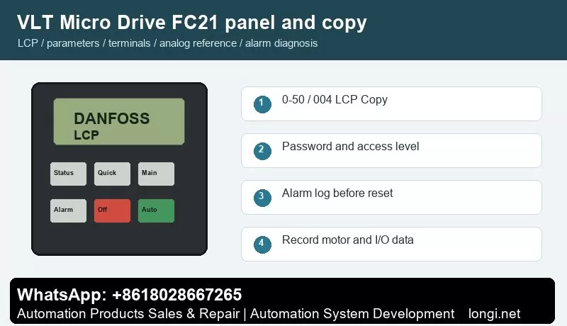
The FC21 LCP uses Menu, arrow keys, OK, Back, Off/Reset, Local Control and Remote Control to select menus, edit parameters and switch between local and remote operation. Status LEDs indicate power, warning and alarm state.
Use the status display first to check frequency, current, reference, direction, terminal state and alarm number. Use the quick menu for motor data, acceleration/deceleration and basic limits. Use the main menu for I/O, analog scaling, protection, bus communication and advanced functions.
Parameter 0-50 LCP Copy supports all parameters to LCP, all parameters from LCP and rating-independent parameters from LCP. Stop the drive before copying and record motor nameplate and application parameters. For a different rating, copy only rating-independent parameters and recheck current, thermal protection and limits.
Parameter copying is useful for replacement drives and repeat machines. Before copying, record motor nameplate data, start source, reference source, terminal functions, relay functions, brake settings, communication address and alarm action. If the new drive rating is different, do not copy all parameters blindly.
Access Restriction and Password Recovery
Use 0-60 Menu Password and 0-61 access without password. 0-61 can be full access, LCP read-only or LCP no access. For handover, allow operators to view status and reset common faults while keeping commissioning parameters password protected.
In service work, divide access into three levels: operators may start, stop, reset and view status; maintenance staff may read alarm logs and terminal states; commissioning engineers may edit motor, I/O, reference, communication and protection parameters. If a drive is locked, try the valid password first. If initialization is unavoidable, back up or photograph all available data before restoring defaults.
External Forward/Reverse Terminal Control
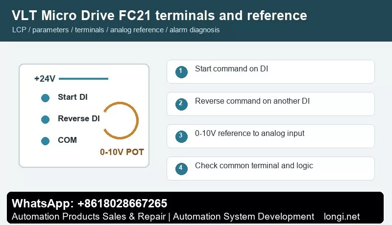
Terminals 12/13 provide control supply and terminal 20 is common. Set terminal 18 with parameter 5-10 for start. Terminal 27 with parameter 5-12 can be set for reverse, reset or preset reference. For forward/reverse control, use one input for start and one independent input for direction.
Use one digital input for start and another for reverse direction. Confirm +24 V, common terminal and input logic with a meter before connecting PLC outputs, switches or relays. After wiring, watch the terminal state on the LCP before running the motor. Test at low speed first, especially on pumps, fans, conveyors and spindle applications.
External Potentiometer Speed Reference
Terminal 50 provides +10 V, terminal 53 is analog input and terminal 55 is common. A 2-10 kOhm potentiometer is typical: high end to 50, low end to 55 and wiper to 53. Set 6-10 to 0 V, 6-11 to 10 V, 6-14 to low reference and 6-15 to the required maximum frequency.
A potentiometer reference only works correctly when the hardware input type, reference source, low/high scaling and frequency limits match. Measure the analog input at minimum and maximum position. If the drive reports wire break or the speed is nonlinear, check common wiring, shield grounding, voltage/current selection and low/high scaling before replacing the control board.
Fault Codes and Troubleshooting
- Alarm 2, Live Zero Error: terminal 53 signal is below 50% of the low-limit value. Check potentiometer open circuit, common terminal, shielding and parameter 6-10.
- Alarm 7/8, Overvoltage or Undervoltage: inspect supply fluctuation, deceleration time, brake unit and DC link.
- Alarm 9/10, Drive Overload or Motor Overtemperature: verify motor data, cooling fan, mechanical load and switching frequency.
- Alarm 13/14/44/16, Overcurrent, Earth Fault or Short Circuit: inspect motor insulation, output cable and moisture or contamination on terminals.
- Alarm 47, Control Voltage Fault: the 24 V load may be excessive or shorted. Remove external terminal loads and test again.
- Alarm 84/86/87/88, LCP Communication, Copy or Data Error: reseat the LCP and confirm model and software version.
- Alarm 90, Parameter Database Busy: avoid writing parameters from LCP and RS485 at the same time.
When troubleshooting, record the alarm number, frequency, current and DC link voltage at the moment of trip. If the drive runs without load but trips with load, focus on mechanical load, ramp time and motor data. If it trips without a motor, check output stage, brake circuit, internal supply and control board.
Field Checklist
- Before power-on: input voltage, grounding, motor insulation, brake resistor and cooling path.
- After power-on: panel status, terminal state, alarm log and access level.
- Before running: motor nameplate, command source, reference source, speed limits and ramps.
- Terminal control: test start, reverse, reset and interlock one by one.
- Analog reference: measure the actual signal and then set low/high scaling.
- Before delivery: save a parameter backup and document modified parameters and password policy.
Conclusion
The correct way to use the VLT Micro Drive FC21 manual is simple: use the panel to confirm status, parameter copy for backup and recovery, access restriction to prevent wrong edits, digital inputs for command logic, analog scaling for speed range, and alarm logs for troubleshooting direction.