
Danfoss FC51 Practical Manual Guide for Service Engineers: LCP Copy, Password Access, Terminal Control and Analog Speed Reference
Why This FC51 Guide Was Rewritten
The FC51 is a small drive, but it is often installed on machines where downtime is expensive: auxiliary conveyors, dosing screws, small pumps, cooling fans, textile units and compact retrofit panels. A generic parameter summary is not enough for this model because the same symptom can come from several different sources. A terminal start failure may be caused by Auto On not being active, by terminal 27 being used as a stop input, by a missing common on terminal 20, or by a reference source that still points to the keypad.
This rewritten guide treats the FC51 manual as a service workflow. It separates local panel operation, parameter copy, password access, external forward/reverse control, 0-10V speed reference and fault code analysis. The goal is to help a technician restore a machine without guessing or replacing the drive unnecessarily.
LCP 11 and LCP 12: What to Check Before Editing Parameters
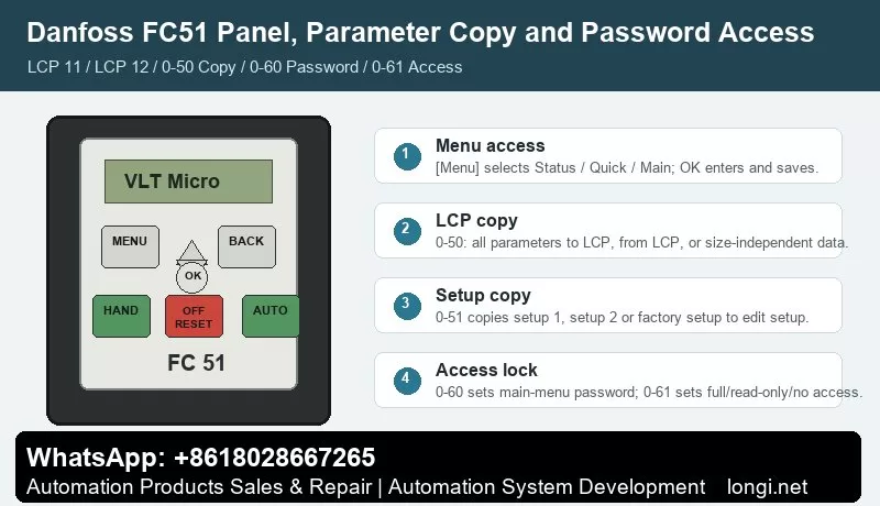
The FC51 normally uses LCP 11 without a potentiometer or LCP 12 with a built-in potentiometer. Both panels give access to Status Menu, Quick Menu and Main Menu. Status Menu is the first place to look because it shows whether the drive is actually receiving a run command and whether the reference value is zero. Quick Menu is useful for motor nameplate data and basic ramps. Main Menu is required for digital input, analog input, password and copy parameters.
Hand On, Off/Reset and Auto On must be understood before terminal control is tested. Hand On runs the drive from the keypad. Off/Reset stops and resets. Auto On allows terminal or serial control. If a technician tries to start from terminal 18 while the drive is left in local mode, the wiring may look wrong even when it is correct.
On LCP 12, the panel potentiometer is not the same as an external potentiometer wired to terminal 53. During troubleshooting, write down whether speed reference is coming from keypad, LCP potentiometer, terminal 53, preset reference or communication.
Parameter Copy: 0-50 LCP Copy and 0-51 Setup Copy
Parameter 0-50 LCP Copy is used to move settings through the removable LCP. Use All to LCP on the source drive, then All from LCP on a target drive with the same rating and hardware. If the target drive is a different size, use the size-independent option and then manually confirm motor current, overload protection, current limit, braking and analog scaling.
Parameter 0-51 Setup Copy is different. It copies setup data inside the same drive. This is useful when the machine has two operating recipes, for example manual jog and automatic production. A good practice is to finish setup 1, copy it to setup 2, and change only the reference source or ramp values that are different.
Do not copy while the machine is running. Stop the drive, wait until the motor has coasted down, and keep a written record of motor data, terminal assignments, reference source and fault action before replacing hardware.
Password Access and Unlocking Without Losing the Machine Setup
Use 0-60 Main Menu Password and 0-61 Access to Main Menu without Password to control who can change parameters. Use 0-65 Quick Menu Password when operators should view status but not change commissioning data. In a service panel, operators normally need status, start/stop and reset; they do not need to edit motor current, terminal logic or analog scaling.
If the FC51 is locked, do not initialize it immediately. First ask for the commissioning password, check the machine documentation, photograph visible parameter screens and save the LCP copy if possible. Initialization is the last step because it can erase the real application logic.
External Forward/Reverse Wiring
The common terminal logic is simple but easy to miswire. Terminal 12/13 provides the control supply, terminal 20 is the common terminal, terminal 18 is commonly used for start, terminal 27 is often used for coast stop or another digital function, and terminal 29 or 33 may be assigned to jog, reverse or preset reference depending on the application.
For a two-wire forward/reverse selector, use one input as the run command and a second input as reverse direction. For a three-wire station, separate start, stop and direction. Always test terminal state on the LCP before connecting the motor to the machine. If the drive shows a run command but output frequency remains zero, check reference source and minimum reference before changing the power circuit.
External 0-10V Potentiometer Reference
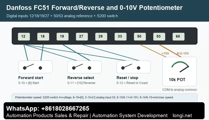
For a standard external potentiometer, wire one end to terminal 50 (+10 V), the other end to terminal 55 (analog common), and the wiper to terminal 53. Then set the reference source to analog input 53. Low voltage should correspond to the minimum reference and high voltage should correspond to the maximum speed required by the machine.
If the drive reports live zero, the analog signal is below the configured threshold. Check whether terminal 53 is set as voltage input, whether the common wire is actually connected to 55, whether shield grounding is creating noise, and whether the potentiometer value is appropriate. A stable 0-10 V measurement at the terminal is more useful than changing random parameters.
Fault Codes That Matter Most on FC51
Live zero / wire break: terminal 53 is below the expected signal. Measure voltage between 53 and 55.
Overvoltage: deceleration is too short, load inertia is high, or braking is not working. Increase deceleration time before replacing hardware.
Undervoltage or phase loss: check supply voltage, input contactor and fuses.
Overcurrent or short circuit: disconnect the motor and test insulation between U/V/W and earth.
Motor overload: verify motor nameplate data and cooling condition.
LCP copy failure: check LCP seating, drive rating, software compatibility and whether the motor is stopped.
Related Danfoss Manual Guides
For older compact VLT installations, compare this FC51 workflow with the Danfoss VLT2900 manual guide.
For another micro-drive family, see the Danfoss FC111 manual guide.
Final Service Note
The revised article is intentionally more specific than the previous version. It gives a technician a model-aware procedure instead of a repeated manual summary, and it adds internal context that should make the page more useful for search engines and real users.