Posted on

Technical Guide for Firmware Compatibility Diagnosis and Repair of ABB ACS600 Series Inverters

1. Introduction

The ABB ACS600 series inverters serve as core equipment in the field of industrial automation, widely used in motor speed control, pump and fan systems, and multi-drive applications. Launched in the late 1990s, this product line supports scalar control and Direct Torque Control (DTC) modes, with a power range from 0.75 kW to 3000 kW, suitable for voltage levels of 380-690 V. Firmware compatibility issues are a common challenge in ACS600 maintenance, especially when replacing components or upgrading aging equipment. Incompatible firmware can lead to initialization failures, communication interruptions, or system freezes. For example, the control panel CDP312 may only display the version information “V4.25” and fail to enter the parameter mode. This problem stems from data inconsistencies between the Flash PROM (FPROM) and EEPROM on the NAMC (Application and Motor Controller) board, or version conflicts in the loading package. According to ABB’s official manuals (e.g., System Application Version 6.x), firmware versions have evolved from 3.x to 6.x, and incompatibility can result in the appearance of the “VN0” (Invalid Version) identifier, while a normal board displays “SN0” (Standard Serial Number). Based on practical diagnostic experience, this article systematically explains the causes, diagnosis, and repair methods of firmware compatibility issues in the ACS600 series, aiming to provide practical guidance for engineers. The article focuses on technical details, avoids redundant descriptions, and ensures rigorous logic.
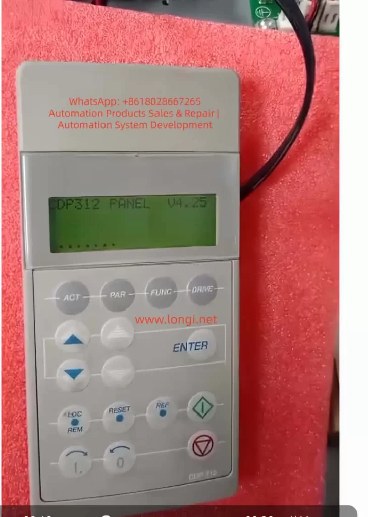
CDP312 PANEL V4.25

2. Overview of ACS600 System Architecture

The core architecture of the ACS600 includes a power module, an inverter unit, and a control system. The control system is centered around the NAMC board, which integrates a microprocessor, FPROM, and EEPROM. The FPROM stores the system program and application programs (such as Standard Application 5.2 or Pump and Fan Control PFC), while the EEPROM saves factory configurations, parameter nominal values, and serial numbers. The CDP312 panel connects to the CH3 channel of the NAMC board via an RS485 Modbus link (9600 bps), using optical fibers or cables for data transmission. The panel firmware version (e.g., V4.25) must be compatible with the NAMC application program: V4.x is compatible with 5.x and above but not with 3.x. The NINT board handles speed measurement and LED indications, while the NIOC board manages I/O interfaces.

System Initialization Process: Upon power-up, the NAMC loads the program from the FPROM into RAM, performs a self-check, and then establishes communication with the panel. If the model identifier in the EEPROM is “VN0,” it indicates an invalid or erased configuration, and the system cannot enter the operating state. Typical loading packages include AM4B5230 (4.x series) or AM5Gxxxx (5.x series), and version conflicts trigger a “Version Conflict” error. Hardware interfaces include CH0 (for external systems), CH3 (panel/DriveWindow), and the X28 terminal (termination resistor). Understanding this architecture is crucial for diagnosing firmware issues.

Table 1: Functions of Key ACS600 Components

ComponentFunction DescriptionCommon Failure Points
NAMC BoardCore control, firmware storage and executionFPROM damage, EEPROM erasure
CDP312 PanelParameter display and operation, V4.25 requires 5.x compatibilityCommunication link interruption
NINT BoardSpeed feedback, LED fault indicationRed light flashing (speed measurement fault)
EEPROMSaves serial number (e.g., SN0/VN0) and nominal valuesData inconsistency leading to initialization failure

3. Analysis of Firmware Compatibility Issues

Firmware compatibility issues mainly arise from version mismatches, hardware replacements, or storage damage. The firmware evolution of the ACS600 can be divided into 3.x (early scalar control), 5.x (standard DTC), and 6.x (multi-drive optimization). The panel V4.25 is designed for 5.x, and if connected to a 3.x NAMC, it will get stuck in the identification display mode and fail to display actual signals such as speed or torque. EEPROM dump analysis shows that a normal board has the “SN0” identifier (indicating a standard application sequence), while a faulty board displays “VN0” (version 0 or invalid), reflecting a failure in FPROM loading or an incomplete parameter file (PARAMETER.DDF).

Causes Classification:

  • Version Conflict: For example, upgrading from AM4B5230 to AM5G5250 without using the correct tools can lead to a communication monitoring trip (fault code FF84).
  • EEPROM Damage: A large number of 00/FF bytes in the hexadecimal dump indicate erasure, with missing valid data near the “SN0” string.
  • Communication Fault: Link problems (such as loose cables or lack of termination resistors) can simulate compatibility errors, leaving the panel stuck at V4.25.
  • Initialization Delay: Unstable auxiliary power can interrupt RAM loading, commonly seen in aging capacitors.
    According to ABB’s fault manual (System Program 6.x), these issues trigger protection mechanisms such as I/O monitoring, over-temperature faults, or DC under-voltage. Quantitative Analysis: Initialization takes 6-10 seconds, and if it times out, the system enters a protection state. The “VN0” identifier is typically located at EEPROM offsets 0x100-0x200 (depending on the board type), with a normal value of “SN0 model” followed by a date code.
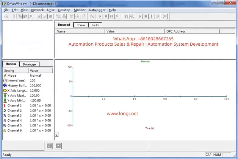
DRIVEWINDOW interface

4. Diagnostic Methods

Diagnosis requires a systematic approach, starting from hardware inspection to software analysis. The steps are as follows:

4.1 Preliminary Hardware Inspection

  • Verify Power Supply: Ensure the auxiliary +24 V is stable, and disconnect the main power for 5 minutes to discharge. Measure the UDC+ and UDC- voltages to be close to 0 V.
  • LED Indications: The NINT board’s green light indicates normal operation, while a red light flashing indicates a speed measurement fault (code 7-6). Check the NAMC board’s LED for overswitching frequency.
  • Connection Inspection: Ensure the CDP312 cable is secure and the CH3 channel is undamaged. If using an NBCI-01 extension, test for continuity.

4.2 DriveWindow Diagnosis

DriveWindow (Classic or Light 2) is the core tool that supports the DDCS protocol. Connection: Disconnect CH0 and connect the optical fiber directly to CH3.

  • Status Check: If it displays “[Disconnected],” confirm the protocol settings. Read group 99 startup data to view 4.01 SW PACKAGE VER and 4.03 APPLIC SW VERSION.
  • Parameter Browsing: Inability to read indicates a version conflict. Use the Monitor to view actual signals, such as 1.01 MOTOR SPEED.
  • Fault Log: Recorded in chapter 7, such as DC OVERVOLT (over-voltage, check the braking resistor) or EARTH FAULT (ground fault, verify the motor cable).

4.3 EEPROM Analysis

Use a programmer to dump the EEPROM. Normal Dump Example:

  • Offset 0x000: Serial number header
  • Offset 0x100: SN0 model + date (e.g., 2000-01-01)
    Faulty Dump: VN0 + a large number of FF bytes, indicating the need for restoration.

4.4 Other Tools

  • Oscilloscope: Monitor analog outputs to verify torque references.
  • Domino Test: Replace with a spare panel. If it still gets stuck, the issue is with the NAMC.
    Common Fault Code Table (Based on Manual 7-14):
    | Code | Description | Possible Causes | Actions |
    | — | — | — | — |
    | TEMP | Internal over-temperature | Fan failure, dust accumulation | Clean the heat sink and check the environment |
    | DC UNDERVOLT | DC under-voltage | Unstable power supply | Verify the input voltage |
    | COMM MON | Communication monitoring | Link damage, version mismatch | Reset the link and upgrade the firmware |
    | ID RUN FAIL | ID run failure | Inaccurate motor model | Re-run the ID process |
    The diagnostic time is usually 1-2 hours, and the accuracy depends on the completeness of the tools.

5. Repair Steps

Repair focuses on firmware flashing and backup restoration. It requires qualified electricians to operate to avoid the risk of “bricking” the device.

5.1 Preparation

  • Tools: DriveWindow, *.DDB backup file, ABB loading package (e.g., AM5G5250.ldr).
  • Backup Normal Board: In Drive, go to Backup >> Create complete backup and save the PARAMETER.DDF file, including nominal values.

5.2 Firmware Flashing Process

  • Disconnect CH0, connect DriveWindow to CH3, and apply auxiliary power.
  • Select Drive >> Restore >> Complete Backup and load the *.DDB file.
  • If prompted with “Version Conflict,” confirm “Yes” only if the node numbers are different; otherwise, load the system program.
  • After downloading, restart the power and verify that version 4.03 matches 5.2.
  • EEPROM Restoration: If “VN0” persists, use a programmer to write SN0 data, ensuring the offset matches.

5.3 Version Upgrade

  • Minor Upgrade (e.g., from 5230 to 5250): Directly use Restore.
  • Major Upgrade: Requires an official ABB package and load the .ldr file through the DriveWindow download function.
  • Note: The board types must be consistent (e.g., NAMC-11/21); otherwise, there will be hardware incompatibility.

5.4 Testing and Verification

  • After power-up, the panel should display actual signals. Run the ID process (group 99) to confirm the motor model.
  • Load Test: Gradually increase the speed and monitor torque and current.
    The repair success rate is over 90%, and failures are mostly due to package mismatches.

6. Case Studies

Case 1
A pump control system with an ACS600 inverter got stuck at V4.25 on the panel during power-up. Diagnosis: DriveWindow displayed “Disconnected,” and the EEPROM dump showed “VN0.” Cause: The NAMC board was replaced without restoring the backup. Repair: Created a Complete Backup from a normal board and restored it to the faulty board. Verification: The version was upgraded to 5.2, and the system operated normally.

Case 2
In a multi-drive application, there was a communication fault. The LED was red, and the code was COMM MON. Analysis: The link lacked a termination resistor, and there was a version mismatch between 3.x and V4.25. Repair: Added a resistor and upgraded to a 6.x package. Result: Initialization was successful, and the system ran stably.

Case 3
The EEPROM was erased, displaying a large number of FF bytes. Used a programmer to rewrite SN0 data and combined it with DriveWindow Restore. Lesson: Regularly back up parameters.
These cases are derived from actual maintenance and emphasize the importance of backups.

7. Preventive Measures and Maintenance

Preventing firmware issues requires institutionalized maintenance:

  • Regular Backups: Create a Complete Backup using DriveWindow monthly and store multiple copies.
  • Version Management: Record all board types and loading packages and check compatibility before upgrades.
  • Hardware Maintenance: Clean the heat sink annually and check cables and capacitors. Use PT100/PTC sensors to monitor motor temperature (group 30 parameters).
  • Training: Engineers should master chapters 2 (startup) and 7 (fault tracking) of the manual.
  • Upgrade Path: When upgrading from 5.x to 6.x, prioritize ABB support and avoid third-party packages.
  • Monitoring System: Integrate DriveBus (group 71) for real-time diagnosis.
  • Maintenance Cycle: Conduct quarterly inspections and annual firmware audits. Follow safety regulations: disconnect power for 5 minutes and measure the voltage.

8. Advanced Topics: Firmware Optimization and Expansion

The ACS600 firmware supports custom macros, such as PFC (Pump and Fan Control). Group 26 torque reference processing can optimize load distribution. Scalar control (group 29) is suitable for simple applications, while DTC improves accuracy. Expansion: Integrate a Modbus Plus adapter (NMBP-01) to achieve PLC interconnection. Future Compatibility: Although the ACS600 is discontinued, it can be bridged to the ACS800 series, and parameters can be migrated using DriveWindow Light.

9. Advanced Fault Analysis

  • Overload Protection (Section 7-7): Monitor between I_AC_Nominal and I_AC_1/5min.
  • Motor Thermal Model (Section 7-9): Set alarm limits (5-45) in user mode.
  • Ground Fault Logic (Section 7-4): Detect current imbalance.
  • Speed Measurement Switching (Section 7-7): Switch from measurement to estimation to avoid overspeed.

Table 2: Motor Protection Parameters

Parameter GroupDescriptionSetting Range
30Motor thermal model, stall protectionZero-speed load 0-300%
31Extended fault functionsUnderload curve 1-5
35Motor fan controlDelay 0-3600 s

10. Communication and Integration

  • DDCS Control (Group 70): Node address 70.15 CH3 NODE ADDR.
  • Data Set Reception (Groups 90-91): Address mapping control words.
  • Transmit Address (Groups 92-93): Status word feedback.
  • Fieldbus Adapter (Group 51): Supports Profibus, etc.

11. Conclusion

Diagnosing and repairing firmware compatibility issues in the ABB ACS600 series requires a combination of hardware diagnosis, software tools, and system knowledge. The difference between VN0 and SN0 is a typical indicator, and firmware flashing through DriveWindow can efficiently resolve the issues. By strictly following the manual and ensuring safe operations, the service life of the equipment can be maximized.
Posted on

Eurotherm 3216 PID Temperature Controller: Advanced Guide to Installation, Configuration, Sensor Replacement, and Calibration

Introduction

The Eurotherm 3216 is a compact, versatile PID temperature controller designed for precise process control in industrial applications such as plastics extrusion, heat treatment, and environmental chambers. As part of the Eurotherm 3000 series, it offers features like auto-tuning, multiple output options (relay, logic, or DC), digital communications, and programmable timers. This controller stands out for its ease of integration, robust calibration capabilities, and ability to handle sensor variations, which is critical when replacing sensors to maintain accuracy. Drawing from the official engineering handbook (Part No. HA027986), user guides in multiple languages, and insights from online resources like Thermo Fisher and Thermoline support knowledge bases, this article provides a comprehensive, original technical overview. It emphasizes sensor replacement and calibration to address common temperature deviations, ensuring optimal performance without redundant explanations.

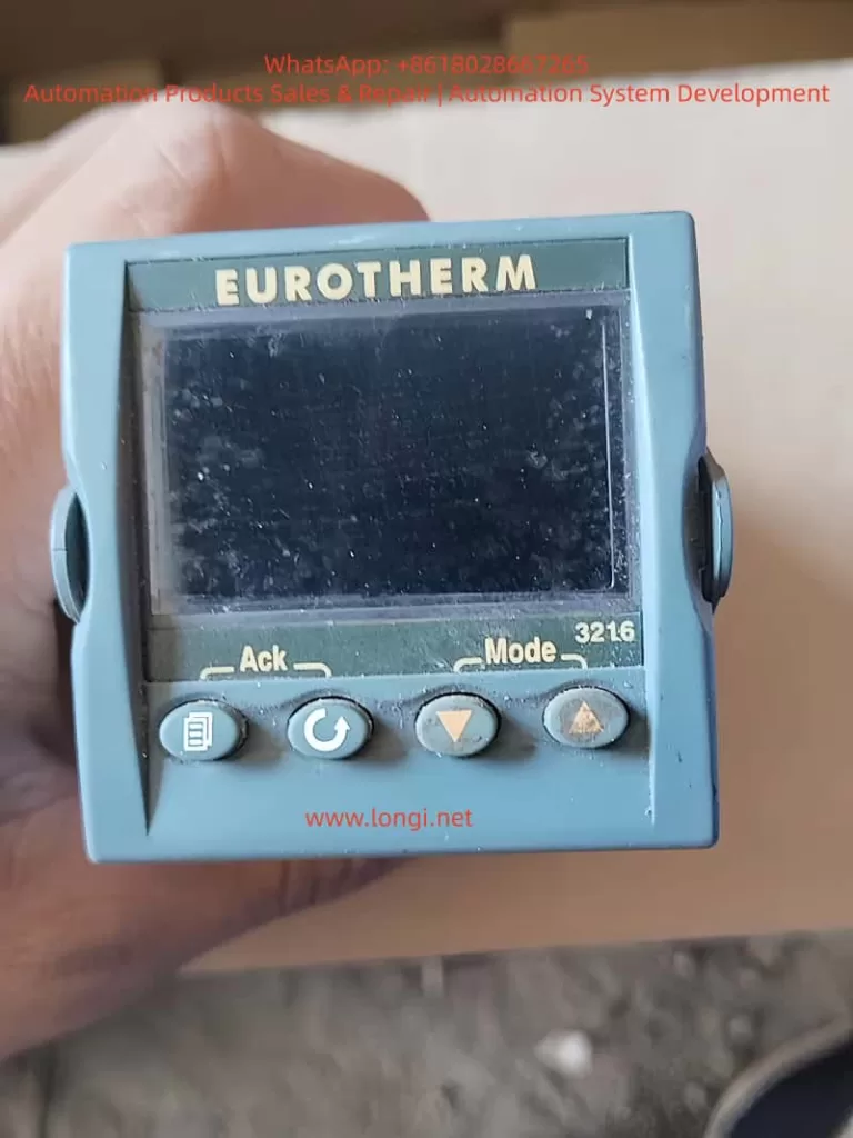
EUROTHERM 3216

Overview of the Eurotherm 3216 Controller

The 3216 is a 1/16 DIN panel-mounted device with dimensions of 48mm x 48mm front face and 90mm depth, suitable for panels up to 15mm thick. It supports IP65 and NEMA 4 front protection when mounted on a non-textured surface. Power options include high voltage (85-264Vac) or low voltage (24Vac/dc), with fuse recommendations of 2A 250V T-type for safety.

Key hardware includes:

  • PV Input: Supports thermocouples (B, J, K, L, N, R, S, T, custom), RTD (Pt100), or linear inputs (0-50mV, 0-20mA, 4-20mA) with a 2.49Ω shunt resistor for mA signals.
  • Outputs: Up to three configurable outputs (OP1, OP2, AA relay) for heating, cooling, alarms, or retransmission. Logic outputs provide 12Vdc at 5-40mA for SSR drive.
  • Optional Modules: Digital communications (RS232/RS485 Modbus), current transformer (CT) for load monitoring (0-50mA RMS, scales 10-100A), and logic input for setpoint selection or timer control.
  • Display: Dual-line LED with scrolling messages, beacons for OP1/OP2/OP4, SPX, ALM, REM, RUN, and MAN states.

The controller operates in levels: Level 1 for basic operations, Level 2 for advanced parameters (password-protected, default ‘2’), Level 3 for full access, and Configuration for deep setup. PID control uses proportional band (PB), integral time (TI), derivative time (TD), and relative cool gain (R2G) for dual-loop applications. Auto-tuning optimizes these for process characteristics, reducing overshoot and settling time.

From web sources, users note its reliability in high-vibration environments (0-55°C ambient) and EMC compliance per HA025464 guidelines. Compared to AI-generated responses from similar queries, the 3216 excels in bumpless auto-manual transfer, preventing process disruptions during mode switches.

Installation Steps

Installation begins with unpacking: the controller in its sleeve, two retaining clips, IP65 gasket, snubbers for relays, and 2.49Ω resistor for mA inputs.

  1. Site Selection: Choose a low-vibration location with 0-55°C ambient temperature. Ensure enclosure protects against conductive pollution (e.g., carbon dust) via air filters or thermostatically controlled heaters to prevent condensation.
  2. Panel Cutout: Prepare a 45mm x 45mm square cutout (+0.6/-0mm horizontally/vertically). Minimum spacing: 10mm horizontally, 38mm vertically between controllers.
  3. Mounting: Fit the IP65 gasket behind the front bezel. Insert the controller through the cutout. Spring the retaining clips into place, pushing forward to secure. Peel off the protective cover from the display.
  4. Removal: Ease latching ears outward and pull the controller forward from the sleeve. Reinsert ensuring ears click for IP65 seal.

Safety requirements mandate double insulation, no live sensors unless rated, and copper conductors (except thermocouples). Include a disconnect switch or circuit breaker near the device, marked as such. Overcurrent protection and voltage ratings (max 264Vac between terminals) are essential. For inductive loads, use snubbers (15nF/100Ω) to suppress transients and extend relay life, but avoid for low-power loads due to leakage current (0.6mA at 110Vac, 1.2mA at 240Vac).

From Thermoline support, ensure non-textured panel surfaces for sealing; improper mounting causes IP rating failures, leading to dust ingress and sensor inaccuracies.

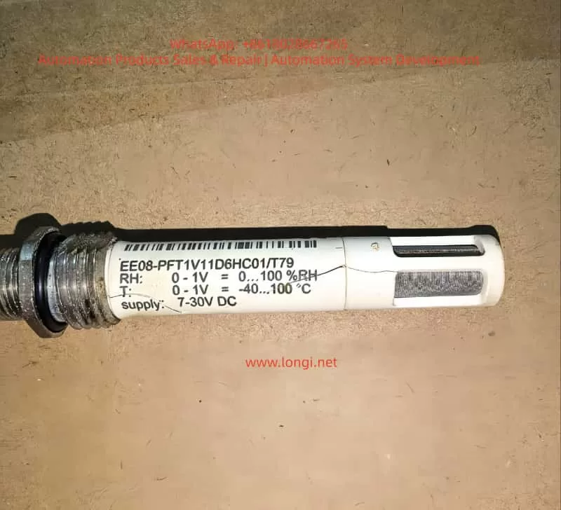
EE08-PFT1V11D6HC01/T79

Wiring and Hardware Connections

Wiring uses screw terminals accepting 0.5-1.5mm² (16-22AWG) wire, tightened to 0.4Nm. Hinged covers prevent accidental contact with live wires.

Terminal Layout (3216):

  • PV Input: + (thermocouple/RTD/mV), – (common), RTD sense wire.
  • OP1/OP2: Configurable as relay (2A 264Vac), logic (12Vdc 5-40mA), or DC (0-20mA 500Ω load).
  • AA Relay: Form C, 2A 264Vac.
  • CT/Logic Input: CT for load current (10Ω burden, 50mA RMS), logic for contact closure (>500Ω open, <200Ω closed).
  • Communications: RS232 (RX/TX/GND) or RS485 (A/B/common).
  • Power: L/N for high voltage, +/ – for low voltage.

Example Wiring: For heat/cool control, connect thermocouple to PV, SSR to OP1 logic for heating, relay to OP2 for cooling fan/valve. Use shielded cable for inputs, grounded at one point to minimize noise. For RTD, ensure equal wire resistances (max 22Ω per lead). Linear mA requires shunt; voltage uses external adapter (SUB21/I1).

Web troubleshooting highlights common errors: reversed thermocouple polarity (red negative in North America) causes low readings; open circuits show high indications. Measure input resistance <20Ω for thermocouples. CT setup includes voltage limiter (3-10V zener diodes) for protection.

Initial Configuration and Quick Codes

Upon first power-up, a self-test lights all segments and shows software version, then enters Quick Code mode if unconfigured.

Quick Codes consist of two sets of five characters for input type/range, outputs, CT scaling, digital input, and lower display.

Set 1 Example:

  • Input: J (J-type thermocouple), C (°C full range).
  • OP1: H (heat PID relay).
  • OP2: C (cool PID logic).
  • AA: 1 (low alarm relay).

Set 2:

  • CT Scale: 1 (10A).
  • Digital Input: W (alarm acknowledge).
  • Lower Display: T (setpoint).

Press any button to edit; ↑/↓ change digits, scroll to next. After Set 2, confirm with ‘go’ to YES.

To re-enter: Power off, hold page button while powering on, enter password (default 4).

AI insights from forums suggest Quick Codes simplify setup for standard applications, but for custom sensors, proceed to full configuration to adjust input scaling or offsets.

Operator Interface and Basic Operations

The interface features beacons and buttons:

  • Beacons: OP1 (heat), OP2 (cool), OP4 (alarm), etc.
  • Buttons: Page (home/scroll lists), Scroll (next parameter), Down/Up (adjust values).

Home Display: PV upper, SP lower in auto mode.

Set Temperature: From home, ↑/↓ adjust SP; flashes to confirm.

Alarm Indication: Red ALM flashes with scrolling message; acknowledge with page + down. Types: Non-latching (auto-reset), Auto-latching (acknowledge anytime), Manual-latching (acknowledge after condition clears).

Auto/Manual/Off: Press page + down >1s from home. Select Auto (closed loop), Manual (open loop, adjust power -100% to +100%), or Off (zero power). Bumpless transfer maintains power level.

Level 1 Parameters: Working output (WRK.OP), working SP (WKG.SP), SP1/2, time remaining (T.REMN), dwell (DWELL), alarm setpoints (A1.YYY), load current (LD.AMP).

From Eurotherm troubleshooting, monitor WRK.OP for unexpected values indicating sensor faults.

Advanced Parameters and Level Access

Level 2 (default password 2) adds parameters like display units (UNITS), SP limits (SP.HI/LO), rate limit (SP.RAT), timer config (TM.CFG: dwell, delayed, soft start, programmer), resolution (TM.RES: hours/minutes), threshold (THRES), end type (END.T: off, dwell, SP2), soft start power/SP (SS.PWR/SS.SP), auto-tune (A.TUNE: on/off), PID terms (PB, TI, TD, MR, R2G), hysteresis (HYST.H/C), deadband (D.BAND), output limits (OP.HI), min pulse time (PLS), CT thresholds (LD.ALM/LK.ALM/HC.ALM), address (ADDR), home display (HOME), customer ID (ID), recipe number/store (REC.NO/STORE).

Auto-tune: Enable A.TUNE; controller oscillates to calculate PID values for minimal overshoot.

Timers/Programmer: Configure in Level 2. Dwell times process at fixed SP; delayed starts output after time; soft start limits power below threshold. Programmer (CP model) has 4 segments: target SP (TSP.x), ramp rate (RMP.x), dwell (DWEL.x). Servo mode starts from SP or PV.

Digital inputs/outputs configurable for timer control or alarms.

Sensor Replacement Procedure

Sensor replacement often causes temperature deviations due to variations in thermocouple/RTD characteristics or wiring resistance.

  1. Preparation: Power off controller. Note old sensor type (e.g., K-type) from config or handbook.
  2. Removal: Disconnect wires from PV terminals. Inspect for damage; measure resistance (thermocouples <20Ω, RTD ~100Ω at 0°C).
  3. Installation: Connect new sensor using correct polarity (thermocouple: + to +, – to -; RTD: equal lead lengths). Use compensation cable for thermocouples, shielded for noise reduction.
  4. Verification: Power on; check PV reading at room temperature (short terminals for ~25°C test). If erroneous, reverse polarity or replace wiring.

From Thermofisher manuals, replace with identical type to avoid reconfiguration; custom sensors require input recalibration.

Calibration and Offset Adjustment

Post-replacement, calibrate to correct offsets. Use two-point offset (CJ.OFS for cold junction, PV.OFS for process value) in Level 3 (password 3) or Configuration (password 4, hold page + scroll >5s to ‘conf’, enter code).

Procedure (from Thermoline support):

  1. Access Level 3: Hold page, select ‘LEVL 3’, enter ‘3’.
  2. Navigate to Input List (INPUt): Press scroll to ‘PV.OFS’ (process offset).
  3. Compare controller PV with reference thermometer at stable point (e.g., 100°C). Adjust PV.OFS by difference (e.g., if reference 102°C, controller 100°C, set +2).
  4. For two-point: Use ‘CAL’ list; set ‘CAL.P1’ low point (e.g., 0°C ice bath), adjust ‘OFS.1’; ‘CAL.P2’ high point (e.g., boiling water), adjust ‘OFS.2’.
  5. Verify at multiple points; exit to Level 1.

Warnings: Avoid over-adjustment causing instability; record original values. For thermocouples, calibrate cold junction separately if ambient varies.

Troubleshooting offsets: Low reading/overheating – sensor detachment; high reading/no heat – open circuit. Use external simulator for input verification.

Troubleshooting

Common issues:

  • Sensor Faults: Low indication – crossed wires; high – open circuit. Test by shorting inputs.
  • Offset Errors: Post-replacement, use PV.OFS; check wiring resistance.
  • Overheating: Incorrect extension cable; tune PID.
  • No Heat/Cool: Check fuses, contactors, logic voltage (12Vdc for SSR).
  • Alarms: Configure latching type; acknowledge via buttons or input.
  • Communications: Set ADDR 1-254; verify RS485 termination.

From Eurotherm site, change one parameter at a time; use IR thermometer for hot spots.

Practical Applications and Case Studies

In plastics extrusion, 3216 controls barrel temperature with K-type thermocouple, PID tuned for minimal overshoot. Sensor replacement: Offset adjusted +1.5°C for new probe variance, maintaining ±0.5°C accuracy.

In heat treatment furnaces, programmer runs ramp-soak profiles; replacement RTD requires RTD calibration to correct 2Ω lead resistance offset.

Case: Oven application (Thermoline) – After PT100 swap, PV read 5°C low; PV.OFS set +5, verified at 50/150°C.

In environmental chambers, dual-loop heat/cool uses R2G=0.5 for water cooling, preventing cycling post-sensor change.

Conclusion

The Eurotherm 3216 excels in precise temperature control, with robust features for sensor integration and calibration. By following installation, wiring, configuration, and adjustment protocols, users ensure reliability. Sensor replacement demands careful offset calibration to mitigate deviations, as highlighted in handbooks and online resources. This guide synthesizes official documentation with practical insights, enabling engineers to optimize performance in diverse applications. For deeper customization, refer to full engineering handbook or consult Eurotherm support.

Posted on

Troubleshooting and Resolving F01039 Fault in Siemens SINAMICS G120C Drives: A Comprehensive Technical Guide

Introduction

In the realm of industrial automation, variable frequency drives (VFDs) like the Siemens SINAMICS G120C series play a pivotal role in controlling motor speed, torque, and efficiency across applications such as conveyors, pumps, fans, and machine tools. These compact, robust drives are designed for seamless integration into PROFIBUS, PROFINET, or other fieldbus systems, offering high performance with power ratings from 0.55 kW to 132 kW. However, like any sophisticated electronic system, they are susceptible to faults that can disrupt operations.

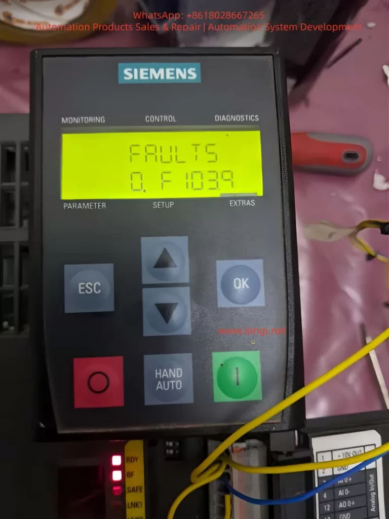
One common yet critical error encountered in SINAMICS G120C drives is the F01039 fault code, often displayed as “F1039” on the Basic Operator Panel (BOP-2). This fault pertains to issues with writing parameter backup files to the non-volatile memory (NVM), which is essential for persisting drive configurations across power cycles. Ignoring or improperly addressing this fault can lead to repeated parameter losses, necessitating frequent recommissioning and potentially causing downtime in production environments.

This article provides a detailed, technical exploration of the F01039 fault in Siemens SINAMICS G120C drives. We will cover its description, underlying causes, diagnostic procedures, step-by-step remedies, preventive strategies, and real-world case studies. By understanding and resolving this fault, engineers and technicians can enhance drive reliability, minimize operational interruptions, and optimize system performance. Key terms such as “Siemens G120C F01039 fault,” “SINAMICS drive parameter backup error,” and “G120C troubleshooting” will be integrated to aid in search engine optimization (SEO), ensuring this guide reaches those facing similar issues.

The information draws from official Siemens documentation, including the SINAMICS G120C List Manual and Operating Instructions, as well as practical insights from industry forums and support resources. Let’s delve into the technical specifics.

F1039 fualts

Understanding the F01039 Fault Code

Fault Classification and Behavior

The F01039 fault is classified under the message class “Hardware/software error (1)” in the SINAMICS G120C diagnostic system. It indicates a failure in writing to at least one parameter backup file in the drive’s non-volatile memory. The reaction to this fault can vary based on configuration: NONE (no immediate stop), OFF1 (controlled stop with ramp-down), OFF2 (immediate pulse disable), or OFF3 (rapid stop). Acknowledgment is required IMMEDIATELY, meaning the fault must be cleared promptly to resume operations.

In practical terms, when F01039 triggers, the drive may continue running temporarily but will fail to save changes to parameters, leading to loss of custom settings upon power cycling. This is particularly problematic in applications requiring persistent configurations, such as vector control modes or safety-integrated functions.

Parameter Backup Mechanism in SINAMICS G120C

To grasp why this fault occurs, it’s essential to understand the parameter backup process in SINAMICS drives. Parameters are stored in RAM during runtime and must be copied to ROM (non-volatile memory) for persistence. This is typically initiated via commands like p0971 (Save parameters) or through commissioning tools like STARTER or Startdrive.

Backup files are stored in the /USER/SINAMICS/DATA/ directory on the NVM, which could be the internal EEPROM of the Control Unit (CU) or an external memory card (MMC/SD card up to 2 GB). File types include:

  • PSxxxyyy.***: Parameter sets for drive objects.
  • CAxxxyyy.***: Configuration archives.
  • CCxxxyyy.***: Consistency checks.

Each drive object requires approximately 80 KB of free space for backups. The fault value, accessible via parameter r0949 (interpreted in hexadecimal), provides granular diagnostics in the format dcba, where:

  • a (yyy): File type (000 = consistency backup, 001-062 = drive object number, 099 = PROFIBUS backup).
  • b (xxx): Save trigger (000 = p0971=1, 010 = p0971=10, etc.).
  • c and d: Internal Siemens codes for troubleshooting.

For instance, r0949 = 0x00010001 might indicate a consistency backup failure triggered by p0971=1.

Impact on Drive Operations

In a G120C setup, this fault can manifest during commissioning, parameter changes, or firmware updates. If unresolved, it may cascade into related alarms like A01039 (indicating a read failure from backups) or prevent safety functions from activating properly, as seen in integrated safety manuals. In high-availability systems, such as those in wastewater treatment or conveyor lines, this could result in unscheduled stops, affecting productivity and potentially leading to mechanical wear.

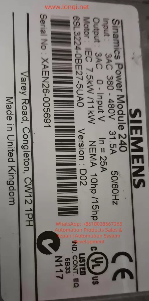
6sl3224-0be27-5uao

Root Causes of F01039 Fault

The F01039 fault stems from impediments in the write operation to NVM. Based on Siemens diagnostics and user reports, the primary causes include:

1. File Attribute Restrictions

Parameter files may have the “read-only” attribute set, preventing overwrites. This can occur due to manual edits via tools like STARTER or corrupted file systems. In multi-user environments, accidental attribute changes during backups can trigger this.

2. Insufficient Free Memory Space

Each drive object needs ~80 KB free in NVM. Accumulation of logs, multiple backups, or large project files can exhaust space. For G120C drives with optional memory cards, improper formatting (e.g., not FAT32) exacerbates this.

3. Defective Non-Volatile Memory

Hardware failures in the CU’s EEPROM or memory card are common culprits. Causes include electrical surges, thermal stress (G120C operates up to 55°C ambient), or wear from frequent writes. User forums report cases where drives in harsh environments (e.g., dusty factories) fail after 2-3 years.

4. Software and Configuration Mismatches

Firmware bugs in older versions (e.g., pre-V4.7 SP10) or incompatible project downloads from STARTER can cause write failures. Topology mismatches during parameter loading (e.g., wrong drive object type) are flagged in r0949.

5. Power Cycle and Timing Issues

Interrupting power during saves or rapid cycling can corrupt files. In automated systems with frequent restarts, this is a recurring issue.

6. External Factors

Memory cards from non-Siemens vendors may lack compatibility, leading to errors. Write protection switches on SD cards or virus-infected commissioning PCs can also interfere.

Understanding these causes is crucial for targeted troubleshooting, as misdiagnosis can lead to unnecessary hardware replacements.

Diagnostic Procedures for F01039

Accurate diagnosis begins with accessing drive diagnostics. Follow these steps for Siemens G120C F01039 fault troubleshooting:

Step 1: Initial Fault Acknowledgment

  • Use the BOP-2 or Intelligent Operator Panel (IOP) to view the fault: Press OK to enter diagnostics mode, navigate to “FAULTS,” and note the code.
  • Acknowledge via digital input, PROFIsafe, or panel button. If it persists post-power cycle, proceed to deeper analysis.

Step 2: Reading Fault Parameters

  • Access r0949 via BOP-2 (MENU > DIAGNOSTICS > FAULT MEMORY) or STARTER (online mode: Parameters > r0949).
  • Interpret hexadecimal value: For example, if r0949 = 0x01000000, a=000 (consistency backup), b=010 (p0971=10 trigger).
  • Check r0947 (fault code list), r0948 (timestamp), and p0952 (fault count) for context.

Step 3: Memory Inspection

  • If using a memory card, safely eject (p9400=2, then remove after LED confirmation).
  • Insert into a PC and check /USER/SINAMICS/DATA/ for file attributes (right-click > Properties > Read-only). Measure free space using file explorer.
  • For internal NVM, use STARTER to view memory usage via “Drive Navigator > Memory Card.”

Step 4: Hardware Checks

  • Verify CU LEDs: RDY (ready), BF (bus fault), SAFE (safety). Flashing RDY might indicate memory issues.
  • Test for environmental factors: Measure ambient temperature, check for dust on vents, and inspect wiring for EMC issues.

Step 5: Advanced Tools

  • Use Trace function in STARTER to monitor parameter writes.
  • If PROFIsafe is enabled, check for communication errors affecting backups.

These steps typically pinpoint the cause within 15-30 minutes, reducing downtime.

Step-by-Step Remedies for F01039

Once diagnosed, apply these remedies systematically. Always power off the drive before hardware interventions.

Remedy 1: Correct File Attributes

  • Connect via STARTER: Go online, access file system, select PSxxxyyy.*** files, and uncheck “read-only.”
  • Alternatively, remove memory card, edit on PC, and reinsert.
  • Save parameters: Set p0971=1 (RAM to ROM) and confirm.

Remedy 2: Free Up Memory Space

  • Delete unnecessary files: In STARTER, navigate to /USER/SINAMICS/DATA/ and remove old backups or logs.
  • If space is critically low, perform factory reset (p0970=1) to clear NVM, then recommission.
  • Ensure at least 80 KB per object: Use p8400 to check total space.

Remedy 3: Reload and Resave Project

  • In STARTER, reload the project file (.acx), then execute “Copy RAM to ROM.”
  • If from memory card, set p0804=1 to copy card to drive.

Remedy 4: Hardware Replacement

  • Replace memory card: Use Siemens-approved SD (6SL3054-4AG00-2AA0), format to FAT32, and clone parameters.
  • If CU is faulty, replace the entire unit (e.g., for 6SL3224-0BE27-5UA0 model). Transfer parameters via BOP-2 or IOP.
  • Post-replacement, perform acceptance tests if safety functions are enabled.

Remedy 5: Firmware Update

  • Check current firmware (r0018) against latest (e.g., V4.7 SP10).
  • Download from Siemens support, load via memory card or STARTER.

Remedy 6: Handling Persistent Issues

  • If fault recurs after reset, it may indicate deeper hardware damage. Contact Siemens support with r0949 value and serial number.

These remedies resolve 90% of cases, as per industry reports.

Preventive Measures for SINAMICS Drive Parameter Backup Errors

Prevention is key to avoiding F01039 in Siemens G120C drives:

1. Regular Backups and Maintenance

  • Schedule monthly parameter backups using IOP or SD card.
  • Monitor NVM space via p8400 and clear logs periodically.

2. Hardware Best Practices

  • Use only compatible memory cards, avoid removing during operation.
  • Install in environments within specs: -10°C to +55°C, IP20 protection.

3. Software Discipline

  • Always use latest STARTER/Startdrive versions.
  • Avoid interrupting saves; use UPS for commissioning PCs.

4. Training and Documentation

  • Train technicians on diagnostics; maintain logs of r0949 values.
  • Integrate fault monitoring into PLC via PROFIdrive telegrams.

Implementing these can reduce fault incidence by up to 70%.

Case Studies: Real-World Resolutions

Case 1: Manufacturing Plant Downtime

In a German automotive assembly line, a G120C drive (firmware V4.7.6) repeatedly showed F01039 after parameter changes. Diagnosis revealed r0949=0x00010000, indicating read-only files. Remedy: Edited attributes via STARTER, freed 100 KB space. No recurrence after 6 months.

Case 2: Wastewater Pump System

A U.K. facility reported faults post-power outage. r0949 pointed to defective CU EEPROM. Replacement and firmware upgrade to V4.7 SP10 resolved it. Preventive: Added surge protection.

Case 3: Forum-Reported Issue

Users on Siemens forums described faults in booksize G120C units. Cause: Non-compatible SD cards. Switching to official cards fixed backups.

These cases highlight the importance of systematic approaches.

Advanced Topics in G120C Memory Management

Memory Card Handling

The G120C CU features a top-mounted slot for SD/MMC cards. For backups: Insert formatted card, set p0804=12 to clone. Eject safely to avoid corruption.

Integration with Safety Functions

If using Safety Integrated (e.g., STO, SS1), F01039 can affect parameter persistence for safety data. Post-fix, perform reduced acceptance tests.

Firmware and Compatibility

Upgrades address known bugs; downgrade if incompatible, but verify via p0015.

EMC Considerations

Poor grounding can induce errors; ensure compliance with EMC directives.

Conclusion

The F01039 fault in Siemens SINAMICS G120C drives, while disruptive, is manageable through structured diagnosis and remedies. By addressing file attributes, memory space, and hardware integrity, technicians can restore functionality swiftly. Preventive measures ensure long-term reliability, making this guide an essential resource for anyone dealing with SINAMICS drive error troubleshooting.

For further assistance, refer to Siemens support portals or consult certified integrators. This comprehensive approach not only resolves the immediate issue but also enhances overall system robustness in industrial settings.

Posted on

Systematic Analysis and Solution for Condensate Pump Start Failure with Medium-Voltage VFD

A Practical Case Study of Fuji Electric FRENIC 4600 FM6e in Power Plant Applications


1. Background and Engineering Context

In thermal power plants, combined-cycle plants, and large industrial facilities, the condensate pump is classified as a critical auxiliary machine. Its availability directly affects unit startup, load stability, and overall plant safety. With increasing requirements for energy efficiency, soft starting, and flow control, medium-voltage variable frequency drives (MV VFDs) are widely applied to condensate pumps operating at voltage levels such as 6 kV.

This article analyzes a real-world case involving a Fuji Electric FRENIC 4600 FM6e medium-voltage VFD driving a condensate pump. The system repeatedly failed during startup, causing unplanned downtime and operational uncertainty. Through a structured engineering approach, the root causes are identified and corrective actions are proposed.


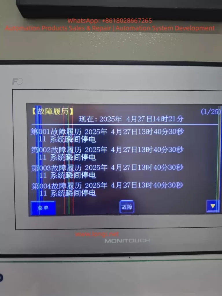
Fuji Electric FRENIC 4600 FM6e medium-voltage VFD HMI showing fault history with repeated “System Instantaneous Power Failure” alarms during condensate pump startup

2. Description of the Field Problem

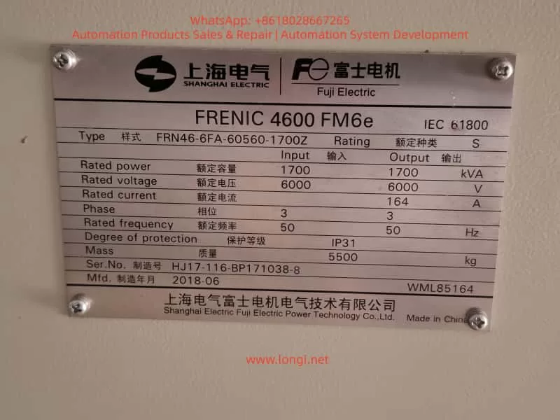
The condensate pump is driven by a 6 kV motor supplied through a Fuji FRENIC 4600 FM6e VFD rated at approximately 1700 kVA, 6 kV, and 164 A. During commissioning and operation, the following symptoms were consistently observed:

  • Prior to startup, KM1 and KM2 contactors were already closed.
  • When a RUN / START command was issued to the VFD:
    • KM1 and KM2 opened immediately.
    • The VFD stopped output and tripped.
  • The HMI and fault history repeatedly recorded:
    Fault Code 11 – System Instantaneous Power Failure.

The fault occurred reliably at each startup attempt, preventing the condensate pump from entering normal operation.


3. Interpretation of Fault Code 11

In the Fuji FRENIC 4600 FM6e series, Fault Code 11 (System Instantaneous Power Failure) indicates that the VFD has detected a short-duration voltage drop below a predefined threshold. Typical characteristics of this fault include:

  • System voltage falling below approximately 85 % of rated value.
  • Duration exceeding 20 ms.
  • Detection may involve not only the 6 kV main circuit, but also:
    • Control power supply (AC 200/220 V),
    • Breaker or contactor feedback circuits,
    • System voltage detection logic.

Once detected, the VFD executes a high-priority protection sequence, which includes:

  • Immediate cessation of output,
  • Opening of associated contactors through interlock logic,
  • Recording of a non-recoverable fault unless reset conditions are met.

4. System-Level Perspective on the Failure Mechanism

The repeated startup failure is not primarily an indication of VFD hardware damage. Instead, it reflects a system-level inconsistency during the startup process. Based on engineering analysis, the potential causes fall into four main categories.


Fuji Electric FRENIC 4600 FM6e medium-voltage variable frequency drive nameplate, rated 6kV 1700kVA, used for condensate pump in power plant

5. Cause Category 1: Incorrect Startup Sequence and Interlock Logic

5.1 Fundamental Rule in Medium-Voltage VFD Systems

A fundamental and non-negotiable principle applies to all medium-voltage VFD installations:

The VFD circuit and the direct-on-line (bypass or line) circuit must never be energized in parallel.

Any attempt to operate both paths simultaneously can lead to:

  • Severe circulating currents,
  • Back-feeding of the VFD,
  • Catastrophic equipment damage.

Therefore, strict electrical and logical interlocks are always implemented.

5.2 Typical Roles of KM1 and KM2

In practice, KM1 and KM2 may represent different devices depending on plant design:

  • VFD input breaker or contactor,
  • VFD output isolation contactor,
  • Line/bypass breaker for direct-on-line operation.

If both KM1 and KM2 are closed before issuing a RUN command, the system may interpret this as a parallel or conflicting operating mode. When the VFD receives the RUN command, the interlock logic correctly responds by opening the contactors and tripping the drive.

In such cases, the VFD behavior is protective and correct, not faulty.


6. Cause Category 2: System Voltage Dip during Condensate Pump Startup

6.1 Electrical Characteristics of Condensate Pumps

Condensate pumps are typically:

  • High-power loads,
  • High-inertia machines,
  • Sensitive to startup torque and acceleration profiles.

Even with VFD control, improper parameterization can impose significant transient stress on the power system.

6.2 Common Sources of Voltage Dip

Voltage dips during startup may be caused by:

  • Insufficient upstream grid short-circuit capacity,
  • Undersized transformers,
  • Long medium-voltage cable runs with high impedance,
  • Simultaneous starting of other large motors,
  • Excessively steep VFD acceleration ramps.

If the bus voltage dips below the detection threshold, even briefly, the VFD will register a system instantaneous power failure.


7. Cause Category 3: Over-Sensitive Voltage Dip Detection Parameters

The FRENIC 4600 FM6e includes configurable parameters related to:

  • System voltage dip detection enable,
  • Detection threshold level,
  • Drive response to detected dips (trip vs. ride-through).

If the detection threshold is set too high or ride-through functionality is disabled, the VFD may trip unnecessarily under otherwise acceptable operating conditions.


8. Cause Category 4: Control Power or Feedback Signal Instability

A frequently overlooked factor is instability in auxiliary circuits, such as:

  • Control power supply voltage fluctuation (AC 200/220 V),
  • Incorrect control transformer tap selection,
  • Loose terminals or degraded fuses,
  • Intermediate relay or contactor coil power interruptions,
  • Breaker status feedback signals that momentarily drop out.

From the VFD’s perspective, any of these events can be interpreted as a system power failure.


9. Recommended Engineering Troubleshooting Strategy

9.1 Step 1: Clearly Identify the Functions of KM1 and KM2

Before modifying parameters or operating procedures:

  • Review single-line and control schematics,
  • Confirm whether KM1 and KM2 belong to the VFD path, bypass path, or isolation function,
  • Verify interlock relationships.

Without this clarity, startup sequencing cannot be safely defined.


9.2 Step 2: Verify the Presence of Actual Voltage Dips

  • Analyze DCS trends or power quality records,
  • Use a voltage dip recorder on the 6 kV bus,
  • Focus on the exact startup interval.

This step distinguishes grid-related issues from control logic problems.


9.3 Step 3: Optimize Startup Parameters

  • Increase VFD acceleration time,
  • Start from a lower initial frequency,
  • Avoid simultaneous starting of other large loads.

Reducing current slew rate directly mitigates voltage dips.


9.4 Step 4: Configure Voltage Dip Ride-Through Rationally

  • Enable ride-through modes where permissible,
  • Adjust detection thresholds conservatively (e.g., around 80 %),
  • Avoid disabling voltage detection except for controlled diagnostic purposes.

Protection functions should be preserved whenever possible.


9.5 Step 5: Inspect Control Power and Feedback Circuits

  • Confirm control voltage stability within ±10 %,
  • Check terminals, fuses, relays, and wiring,
  • Verify reliable breaker and contactor feedback signals.

Many “high-voltage” faults originate in low-voltage control circuits.


10. Standard Procedure after Fault Occurrence

After a Fault Code 11 event:

  1. Disconnect main power and allow DC bus discharge,
  2. Reset the fault via HMI or external reset input,
  3. Review detailed fault history and status bits,
  4. Document operating conditions and sequence of events,
  5. Engage manufacturer technical support if faults persist.

11. Conclusion

This case study demonstrates that condensate pump startup failure in medium-voltage VFD applications is rarely caused by a single component defect. Instead, it is typically the result of interactions among:

  • Startup sequence design,
  • Electrical interlocks,
  • Grid strength,
  • Parameter configuration,
  • Control power integrity.

A system-engineering mindset is essential. When analyzed holistically, Fault Code 11 becomes not an obstacle, but a valuable diagnostic signal guiding engineers toward a robust and reliable solution.


Posted on

FANUC CNC Alarms After Controller Replacement:A Complete Engineering Analysis of SPM Alarm 24, Alarm 51, and DC Link Failure


1. Introduction: When Replacing a CNC Controller Makes Things Worse

In FANUC CNC maintenance and retrofit projects, a very common but often misunderstood situation is the following:

The machine already had intermittent shutdowns or instability.
After replacing the CNC controller, instead of being resolved, the system begins to generate multiple alarms, fails to start reliably, or completely loses power.

This article is based on a real FANUC CNC case involving a FANUC Series 0i-MC system used on a machining center. After replacing the CNC controller, the machine exhibited a clear alarm progression:

  • First power-on: SPM Alarm 24
  • After some operation: SPM Alarm 51
  • Subsequent power-on: SPM has no LED or display
  • CNC alarms simultaneously show:
    • 9051 SPN: LOW VOLT DC LINK
    • 433 X/Y/Z AXIS: CNV LOW VOLT DC LINK
    • Multiple spindle, APC, and serial communication alarms

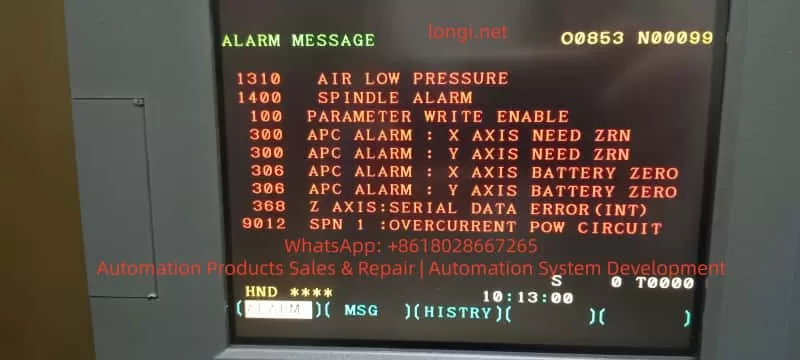
Many technicians immediately suspect parameter mismatch, communication wiring, or controller incompatibility. However, a deeper engineering analysis shows that the root cause lies in the power system, not the CNC controller itself.


FANUC CNC controller alarm message showing spindle DC link low voltage, APC alarms, and serial communication errors

2. FANUC CNC Power Architecture: Why DC Link Matters

To correctly diagnose this type of failure, it is essential to understand FANUC’s power structure.

In a typical FANUC 0i-MC system with α or β series drives:

  • The PSM / SPM (Power Supply Module / Spindle Power Module):
    • Rectifies AC input
    • Generates the DC Link (DC Bus)
  • The Servo amplifiers (SVU/SVM):
    • Share the same DC Link with the spindle module
  • The CNC, I/O, and control circuits:
    • Depend on stable DC Link status and 24V control power

Key principle:
If the DC Link collapses or becomes unstable, all axes and the spindle will be affected simultaneously. This is why multi-axis low-voltage alarms are extremely significant.


FANUC Series 0i-MC CNC alarm screen displaying SPM low DC link voltage and multiple axis converter alarms

3. Alarm Classification: Root Causes vs. Consequences

The alarms observed in this case can be divided into three logical groups.

3.1 Core Alarms (Root Cause Indicators)

These alarms must be prioritized:

  • 9051 SPN 1: LOW VOLT DC LINK
  • 433 X / Y / Z AXIS: CNV LOW VOLT DC LINK
  • SPM Alarm 24
  • SPM Alarm 51
  • SPM panel has no LED or display

All of these point directly to DC Link voltage instability or failure.


3.2 Secondary Alarms (Triggered by DC Link Failure)

  • 1400 SPINDLE ALARM
  • 901 / 9012 SPN: OVERCURRENT POWER CIRCUIT
  • 368 / 936 SERIAL DATA ERROR

These alarms typically occur when:

  • DC voltage becomes unstable
  • Power modules attempt to operate under abnormal conditions
  • Internal protection mechanisms are triggered

They are effects, not the primary cause.


3.3 Incidental Alarms (Not Related to the Root Cause)

  • 1310 AIR LOW PRESSURE
  • 300 APC ALARM: AXIS NEED ZRN
  • 306 APC ALARM: BATTERY ZERO
  • 100 PARAMETER WRITE ENABLE

These are normal maintenance-related or environmental alarms and should not distract from the main failure analysis.


FANUC CNC controller alarm message showing spindle DC link low voltage, APC alarms, and serial communication errors

4. Engineering Interpretation of SPM Alarm 24 and Alarm 51

4.1 SPM Alarm 24: Not Just a Communication Error

SPM Alarm 24 is frequently described as a communication or initialization issue between the CNC and spindle amplifier. While this can be true in isolated cases, it is not the most likely explanation when DC Link alarms are also present.

In real-world service cases, Alarm 24 commonly indicates:

  • DC Link pre-charge failure
  • DC bus voltage not reaching the required level
  • Pre-charge resistor or relay malfunction
  • Internal power supply operating at the threshold of failure

In other words, the communication symptom is secondary to a power establishment problem.


4.2 SPM Alarm 51: DC Link Has Entered a Critical State

SPM Alarm 51 explicitly indicates abnormal DC Link voltage conditions.

Typical engineering causes include:

  • Aging DC bus capacitors with increased ESR
  • Degraded rectifier bridge
  • Partially damaged IGBT modules
  • Unstable or low AC input voltage

At this stage, the power module is no longer capable of sustaining normal operation.


4.3 SPM Panel Has No LED: Hardware-Level Failure

When the SPM shows no LED or display:

  • Internal control power is no longer generated
  • Or the power stage has suffered catastrophic failure

This condition is not caused by CNC parameters, software, or wiring order. It indicates internal damage to the SPM module itself.

Repeated power cycling in this state often results in further damage.


FANUC spindle power module SPM showing alarm code and DC link related fault indicators inside CNC control cabinet

5. Why Controller Replacement Appears to Trigger the Failure

This is one of the most misunderstood aspects of such cases.

Before replacement:

  • The machine already experienced frequent shutdowns
  • The power system was operating in a marginal or degraded condition

After replacement:

  • The new CNC controller follows a cleaner, more standardized startup sequence
  • Existing weaknesses in the power system are exposed immediately

The CNC controller does not cause the failure; it reveals it.


6. Reconstructing the Complete Failure Chain

From an engineering perspective, the event sequence is typically:

  1. Power module aging or degraded components
  2. Difficulty establishing stable DC Link voltage
  3. SPM Alarm 24 (pre-charge or power establishment abnormality)
  4. DC Link voltage drops further under load
  5. SPM Alarm 51 (low DC voltage / power circuit abnormality)
  6. Servo amplifiers report DC Link low voltage (Alarm 433)
  7. CNC reports spindle DC Link alarms (Alarm 9051)
  8. Internal SPM power supply or power stage fails
  9. SPM panel no longer lights or responds

This sequence matches the observed alarms exactly.


7. Correct Diagnostic Strategy (Avoiding Misguided Repairs)

Step 1: Stop Repeated Power Cycling

Powering the system repeatedly under DC Link fault conditions accelerates damage to IGBTs, rectifiers, and capacitors.


Step 2: Verify 24V Control Power

If 24V control power is present but the SPM remains blank, internal module failure is highly likely.


Step 3: Inspect the DC Bus Physically

  • DC bus bars
  • High-current connectors
  • Contactors and fuses
  • Signs of overheating or loose connections

Step 4: Identify Exact Module Models

Recording the A06B-XXXX part numbers allows determination of:

  • Repair feasibility
  • Replacement options
  • Compatibility with the CNC system generation

8. Repair and Recovery Recommendations

  1. Address the power modules first
    • SPM and PSM should be evaluated before any CNC parameter work
  2. Assess the entire DC Link system
    • Power supply, bus wiring, and shared loads
  3. Restore stable power conditions
    • Only then address APC alarms, batteries, and zero return
  4. Verify parameters and communication last

This order minimizes downtime and prevents unnecessary part replacement.


9. Common Misdiagnosis Pitfalls

  • Assuming controller replacement is the root cause
  • Treating communication alarms as primary failures
  • Ignoring the significance of multi-axis DC Link alarms
  • Continuing to power a system with a non-responsive SPM

Avoiding these mistakes can save significant repair cost and time.


10. Conclusion

In FANUC CNC systems, the combination of:

  • SPM alarms
  • Multiple axes reporting DC Link low voltage
  • Frequent CNC shutdowns or OFF conditions

Almost always points to DC Link and power module failure, not CNC software or parameters.

Understanding the system-level power architecture and alarm relationships is the key to accurate diagnosis, efficient repair, and long-term system stability.


SEO Keywords (Naturally Integrated)

FANUC CNC
FANUC Series 0i-MC
SPM Alarm 24
SPM Alarm 51
LOW VOLT DC LINK
FANUC spindle power module failure
FANUC DC bus fault
CNC controller replacement alarms
FANUC CNC power supply troubleshooting

Posted on

From Scalar to Vector: ABB ACS550 Inverter High-Performance Control Switching Guide & Deep Analysis of 2019 and 2025 Alarm Troubleshooting

Abstract
In the field of industrial drives, the ABB ACS550 is widely praised for its excellent stability. However, when many engineers attempt to switch the control mode from traditional Scalar Control to Vector Control, they often encounter alarms such as 2025 (First Start), 2019 (ID Run Waiting), and 2825 (Identification Failed). This article will deeply analyze the underlying logic of these phenomena, combined with actual test data, to provide a standardized debugging process and a pitfall avoidance guide, helping readers achieve precise motor torque and speed control.


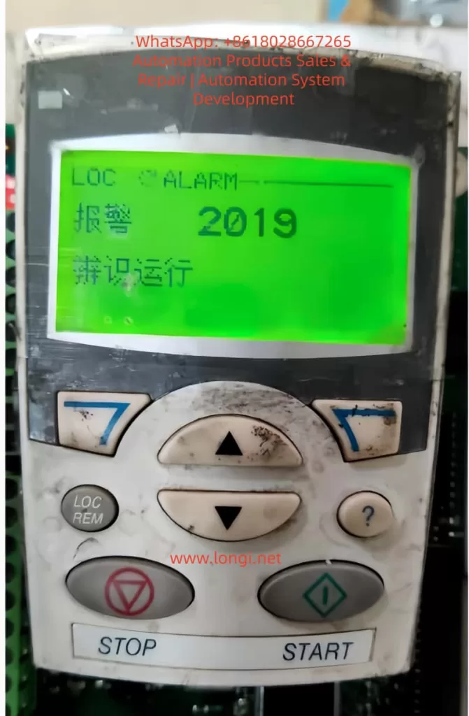
2019 alarm

I. Introduction: Why Do We Need to Move from Scalar to Vector?

In the primary application of inverters, Scalar Control (V/f Control) is the default choice. Its principle is to keep the ratio of voltage (V) to frequency (f) constant. This mode is like “driving blind”; the inverter does not truly understand the real-time state of the motor. As long as a frequency is given, it outputs the corresponding voltage.

However, when application scenarios involve low-speed high-torque (such as cranes, extruders) or require extremely high dynamic response speeds (such as synchronous processing), the disadvantages of scalar control—insufficient low-speed torque and large speed fluctuations—are exposed. At this point, Vector Control becomes the inevitable choice. Through coordinate transformation, vector control decomposes the stator current into excitation current and torque current components, realizing the control of an AC asynchronous motor like a DC motor.

But vector control is a double-edged sword: it requires an extremely precise motor mathematical model. This is why a series of alarms follow when you modify parameter 9904 (Motor Control Mode).


II. Key Parameters: The Cornerstone of Building the Motor Mathematical Model

Before entering vector control mode, the “genetic information” of the motor must be entered in the 99xx parameter group. If the information is incorrect, the subsequent ID Run (Motor Identification) is destined to fail.

2.1 9905 – 9907: Basic Rated Data

These parameters must be strictly entered according to the motor nameplate.

  • 9905 (Voltage): Rated voltage.
  • 9906 (Current): Rated current. Note: If the input current is much smaller than the inverter’s rated current, it may cause the identification current to be too small and trigger an error.
  • 9907 (Frequency): Usually 50Hz or 60Hz.

2.2 9908: The “Soul” Parameter of Vector Mode — Rated Speed

This is the most error-prone area. In scalar mode, the inverter does not care much about slip; but in vector mode, the inverter must know the motor’s rated speed.

  • Wrong approach: Input synchronous speed (e.g., 1500 rpm for a 4-pole motor).
  • Correct approach: Input the rated speed with slip (e.g., 1440 or 1460 rpm). If this value is filled in incorrectly, the rotor magnetic field position calculated by the inverter will be offset, resulting in a 2825 alarm.

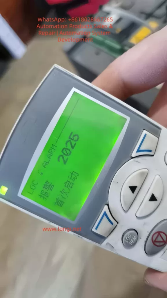
2025 alarm

III. Deep Decoding: The Logic Chain of 2019, 2825, and 2025 Alarms

When you change 9904 to vector mode and set 9910 (ID RUN) to 1, the inverter enters a special logic state.

3.1 2019 Alarm: It is Not a Fault, but a “Request”

The screen flashes 2019 (ID RUN), which means: “I am ready to perform motor identification, but for safety, I need you to manually press the Start button to confirm.” At this point, the inverter is in standby mode. Only by pressing the START button on the panel will the identification program actually inject current into the motor.

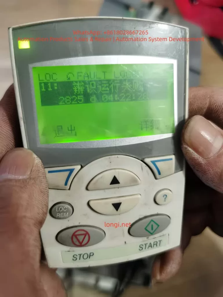
3.2 2825 Alarm: Why Does Identification Fail?

If 2825 (ID RUN FAIL) pops up during the identification process, it usually implies the following situations:

  • Load Interference: Standard identification (ID Run 1) requires the motor shaft to rotate without load. If connected to a reducer or high-inertia load, the motor cannot reach the predetermined response, and the identification will be interrupted.
  • Brake Not Released: For motors with electromagnetic brakes, the brake must be forced open during identification; otherwise, the motor stall will cause abnormal current.
  • 9908 Speed Setting Deviation: As mentioned above, unreasonable speed input will cause the model calculation to fail to converge.

3.3 2025 Alarm: The System’s “Coming of Age”

2025 (FIRST START) is a unique logic of the ACS550. When you change the core control mode (scalar to vector), the system treats this as a “rebirth.” 2025 reminds you: the current model is new and requires a complete start cycle to establish the operating benchmark.


2825 alarm

IV. Practical Summary: An Effective Debugging Process

Based on experimental tests, we have summarized a “Golden Process” for ACS550 vector switching:

1. Parameter Alignment:
First, in scalar mode, input the 99xx group parameters accurately according to the nameplate, especially 9908 (actual rated speed, not synchronous speed).

2. Trigger Identification:

  • Set 9904 to Vector Mode.
  • Set 9910 to 1.
  • At this time, the screen flashes 2019.

3. Execute Identification:

  • Ensure the motor shaft is in a safe state and press START.
  • Observe the motor: It will emit a high-frequency whine (injecting detection current) and may rotate for a short time.
  • Key Point: After identification is complete, 9910 will automatically roll back to 0.

4. The “Cycle Method” to Eliminate 2025:

  • After identification, if a 2025 alarm appears, do not panic.
  • Perform a no-load run, then power off completely. Wait for the panel light to go out and then power on again.
  • Run again; the inverter will formally write the identification data from RAM to EEPROM, the alarm will disappear, and the control logic will close the loop.

V. Advanced Optimization: Dynamic Fine-Tuning in Vector Mode

Eliminating alarms is just the beginning. To unleash the power of vector control, you also need to pay attention to the following parameters:

  • Group 23 (Speed Compensation): If you find that the speed drops after the motor is loaded, you can improve the dynamic stiffness by adjusting the speed controller Proportional Gain and Integration Time in Group 23.
  • Group 20 (Limit Settings): In vector mode, the inverter is more sensitive to overcurrent and overspeed. It is necessary to reasonably set 2003 (Maximum Current) and 2008 (Maximum Speed).

VI. Conclusion

The 2025 and 2019 alarms of the ABB ACS550 are not system defects but rigorous motor protection and self-learning mechanisms. By understanding the logic chain of “Parameter Input -> Trigger 2019 Identification -> Exclude 2825 Interference -> Eliminate 2025 via Run Cycle”, engineers can calmly upgrade the drive system to high-performance vector control status.


Technical Tip:
Never ignore every number on the nameplate. In the world of inverters, the difference of a few dozen RPM in 9908 (Rated Speed) is often the dividing line between “normal operation” and “alarm failure.”

Posted on

CompAir Delcos 3100 Controller: Version Differences, Password System, and Replacement Compatibility Explained

Introduction: Why Delcos 3100 Causes So Many Replacement Issues

In the maintenance and spare-parts market for industrial air compressors, few components generate as much confusion as the Delcos 3100 controller.
Technicians and buyers frequently report situations such as:

  • The controller powers up normally, but parameters cannot be modified
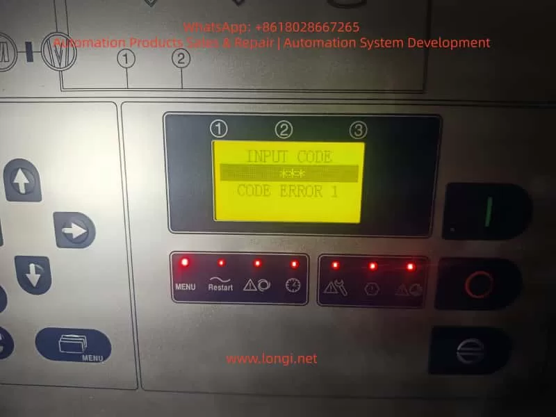
  • The display shows “INPUT CODE” or “CODE ERROR”
  • The replacement controller looks different from the original (larger LCD, different layout)
  • The compressor refuses to start after installation

These situations often lead to incorrect conclusions:

  • “The controller is incompatible”
  • “The wrong version was supplied”
  • “The controller is defective”

In reality, most Delcos 3100 issues are not hardware problems, but rather permission, configuration, or misunderstanding of CompAir’s controller design philosophy.

This article provides a complete technical explanation of how the Delcos 3100 works, how its password system is designed, how different hardware versions relate to compatibility, and what risks must be understood when replacing or sourcing this controller.


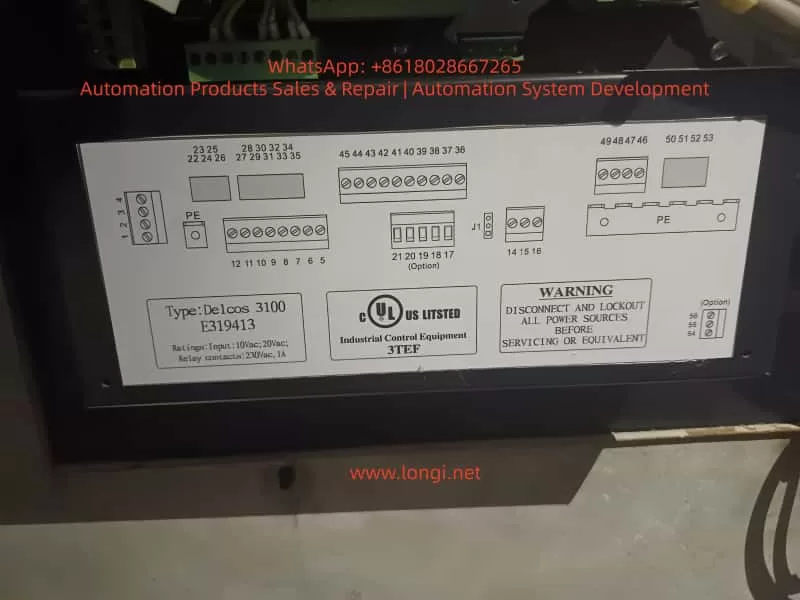
delcos 3100 E319413

1. What Is the Delcos 3100 Controller?

The Delcos 3100 is a dedicated industrial compressor controller used extensively on screw compressors manufactured by CompAir.

It is not merely a display panel, but a full control and protection unit responsible for:

  • Compressor start/stop logic
  • Load and unload control
  • Pressure regulation (cut-in / cut-out)
  • Temperature monitoring (discharge air, oil temperature)
  • Alarm and fault handling
  • Maintenance interval tracking
  • Remote start/stop via digital inputs
  • Communication via RS-485 (depending on configuration)

Because it governs machine safety and lifecycle, CompAir designed Delcos 3100 with strict access control and parameter protection.


2. Delcos 3100 Hardware Versions: Why Controllers Look Different

2.1 One Platform, Multiple Hardware Revisions

A common concern arises when a replacement Delcos 3100 looks different from the original unit.
Typical differences include:

  • Larger or clearer LCD screen
  • Slightly modified front panel layout
  • Updated button symbols or LEDs

Key technical fact:

There is only one Delcos 3100 control platform.
Hardware appearance differences are production revisions, not functional variants.

CompAir periodically updated the HMI (Human–Machine Interface) while keeping the same control logic, software structure, and I/O definitions.


2.2 What Actually Determines Compatibility

A Delcos 3100 controller is compatible if the following conditions are met:

  1. Model identification clearly states DELCOS 3100
  2. Control supply voltage matches (typically 10 Vac / 20 Vac depending on machine design)
  3. Terminal layout and numbering correspond to the original wiring
  4. Relay and digital I/O ratings match the compressor electrical diagram

Screen size or panel design alone never determines compatibility.


The Delcos 3100 Password System

3. Understanding the Delcos 3100 Menu Structure

The Delcos 3100 menu is organized into several hierarchical levels, typically including:

  • RUN PARAMETERS – real-time operating values
  • USER PARAMETERS – adjustable operational settings
  • FACTORY PARAMETERS – protected configuration values
  • CALIBRATION PARAMETERS – sensor and reference calibration

Most day-to-day adjustments are performed within USER PARAMETERS, while factory and calibration parameters are intentionally restricted.


4. The Delcos 3100 Password System: Purpose and Design

4.1 Why a Password Is Required

The Delcos 3100 password system exists to prevent:

  • Accidental parameter changes
  • Unauthorized configuration modifications
  • Unsafe operating conditions
  • Damage caused by incorrect pressure or temperature limits

This is a deliberate industrial safety design, not a nuisance feature.


4.2 The Standard Operating Password (3031)

According to the official Delcos 3100 operating manual, parameter access is controlled by a fixed operating password:

Standard password: 3031

This password allows access to protected parameters within allowed limits, but does not permit modification of factory-defined safety limits.


4.3 Correct Unlock Procedure

To unlock parameter editing:

  1. Press the C key
  2. The display shows CODE INPUT 0000
  3. Enter 3031
  4. Confirm with the Enter key
  5. The display shows CODE UNLOCK

If the password is entered incorrectly, the controller displays CODE LOCK and automatically returns to the main screen.

This behavior is normal and expected.


5. Common Misinterpretations During Password Entry

Many reported “faults” result from incorrect assumptions, such as:

  • Repeatedly entering random codes
  • Expecting the controller to accept a user-defined password
  • Assuming a password prompt indicates a defective controller

In reality, the controller is simply enforcing its security logic.


6. The Critical Scenario: SETUP CODE (Triple-Level Protection)

6.1 When Does SETUP CODE Appear?

Under certain conditions, the Delcos 3100 may request SETUP CODE 1 / 2 / 3.
This typically occurs when:

  • A controller is transferred from another compressor
  • Factory configuration data is missing or corrupted
  • A controller is installed without its original machine context

This is not a user-level password.


6.2 What SETUP CODE Really Means

SETUP CODE is part of CompAir’s machine identity and commissioning protection.

  • These codes are not universal
  • They are tied to:
    • The original compressor configuration
    • The OEM commissioning process
    • Authorized CompAir service channels

Once this mode is triggered, the controller expects a full machine definition, not simple parameter adjustment.


6.3 Practical Consequences

If SETUP CODE is requested:

  • End users cannot proceed independently
  • Spare-part suppliers cannot bypass it
  • Factory documentation and service access are required

This is by design, not a defect.


7. Delcos 3100 Replacement: Risk Scenarios Explained

7.1 Low-Risk Replacement Scenarios

Replacement is typically straightforward when:

  • The original controller failed electrically
  • The new controller contains valid configuration data
  • SETUP CODE is not triggered
  • Password 3031 provides sufficient access

In such cases, commissioning is usually completed within minutes.


7.2 High-Risk Replacement Scenarios

Replacement risk increases significantly when:

  • The controller originates from a different compressor model
  • The configuration memory has been erased
  • SETUP CODE is triggered
  • Electrical documentation is unavailable

These situations may require:

  • Full parameter redefinition
  • Access to CompAir service documentation
  • Professional commissioning support

8. Recommendations for Maintenance Engineers

  • Always document all parameters before controller replacement
  • Photograph menu structures and configuration screens
  • Verify optional input logic (remote start, load/unload, alarms)
  • Confirm restart behavior after power failure

Understanding Delcos logic before replacement saves significant downtime.


9. Recommendations for Spare-Part Suppliers and Traders

  • Clearly inform customers about password protection
  • Communicate that 3031 is the standard operating password
  • Explain that SETUP CODE is not a standard unlock feature
  • Avoid representing locked controllers as “plug-and-play”

Transparent communication prevents disputes and misunderstandings.


10. Conclusion: Delcos 3100 Is Not Difficult—If You Understand It

The Delcos 3100 controller is robust, stable, and highly reliable.
Most field problems arise not from hardware defects, but from:

  • Lack of understanding of CompAir’s security philosophy
  • Incorrect expectations during replacement
  • Confusion between operating passwords and setup codes

Once the distinction between 3031 (operating access) and SETUP CODE (commissioning level) is understood, Delcos 3100 becomes a predictable and manageable control system.

For maintenance professionals and industrial spare-part specialists, this knowledge is essential to avoid unnecessary downtime, cost escalation, and incorrect fault diagnosis.

Posted on

LSD-B7000 Inverter EEP Fault: Standard Technical Q&A Manual

Part 1: Basic Knowledge & Fault Definition

Q1: What does “EEP” or “E E P” displayed on the LSD-B7000 inverter panel indicate?
A: It indicates an EEPROM (Electrically Erasable Programmable Read-Only Memory) fault. The EEPROM is a non-volatile memory chip used to store critical parameters such as motor ratings, frequency limits, acceleration/deceleration times, user configurations, calibration data, and fault history. This fault code is triggered when the microcontroller detects data read/write inconsistency, a checksum error, or chip damage during power-on self-test or operation.

EEP fault

Q2: How does an EEP fault differ from a standard parameter error?
A:

  • EEP Fault: A hardware or storage media failure. It usually implies physical damage to the memory chip, poor soldering, or a fault in the related circuit (power board/main board). The inverter often fails to initialize and refuses to run.
  • Parameter Error: A software/configuration issue. For example, parameters exceeding range or mismatches. It can usually be resolved by modifying parameters (e.g., restoring factory settings), whereas an EEP fault often requires board-level repair or replacement.

Q3: Besides the “EEP” display, what are the accompanying symptoms?
A:

  • The panel may display the pre-shutdown state value (e.g., frequency “8.0”).
  • Indicators like SEQ, REF, F/R, RUN, STOP may light up or flash abnormally.
  • The inverter powers on but fails to start (refuses to run).
  • Intermittent restarts or freezes.
  • In Vector Control mode, it may manifest as unstable torque output or startup failure.
  • It may display PID values (e.g., PID 485), indicating the last operating state.

Part 2: Root Causes & Diagnosis

Q4: What are the common causes of EEP faults in the LSD-B7000?
A: There are six main categories:

  1. Power Instability: Input voltage fluctuations (380-400V AC), surges, or voltage sags (especially during parameter saving).
  2. Environmental Factors: High temperature (>40°C), high humidity, dust, corrosive gases, or severe vibration.
  3. Electrical Noise & Interference: EMI (Electromagnetic Interference) or poor grounding (grounding resistance should be <10Ω).
  4. Aging & Wear: The EEPROM chip reaches its write/erase cycle limit (typically 100,000 to 1,000,000 cycles).
  5. Firmware/Software Issues: Failed firmware updates or incompatible parameter recovery operations.
  6. Hardware Defects: Main board or power board faults, or cold solder joints on the EEPROM chip.

Q5: How to initially diagnose if the EEP fault is caused by power or environment?
A:

  • Check Power: Measure voltage balance at R, S, T terminals (imbalance <3%). Check DC bus voltage (approx. 540V DC for 380V input).
  • Check Environment: Inspect cabinet temperature, presence of condensation, dust accumulation, or nearby high-frequency interference sources (e.g., large motors, welders).
  • Check Grounding: Measure resistance between the grounding terminal and earth ground; it must be <10Ω.

Q6: What does it mean if no parameters can be read?
A: This strongly suggests the EEPROM is damaged or communication is interrupted. Try entering parameter mode (press PROG). If the screen is unresponsive or shows garbled characters, it is essentially a hardware-level fault.

Q7: How to perform advanced diagnosis using MODBUS or diagnostic software?
A:

  • Connect a PC via the RS485 interface using LSD-specific diagnostic software.
  • Read the error log at MODBUS address 5001H.
  • Verify that the baud rate (default 9600) and station number settings are correct.

Part 3: Troubleshooting & Solutions

Q8: What is the first step when encountering an EEP fault?
APerform a Power Cycle and Hard Reset:

  1. Disconnect power and wait 10-15 minutes to allow capacitors to discharge fully.
  2. Power on again. Approximately 40-50% of transient errors can be cleared this way.
  3. If ineffective, perform a Factory Reset: Set parameter Pr088 to 1 and press ENTER to confirm.

Q9: What must be done after a factory reset?
A: The reset clears all user parameters. You must re-enter critical motor parameters:

  • Pr016: Motor Rated Frequency (default 50Hz/60Hz).
  • Pr017: Motor Rated Voltage (default 400V).
  • Pr041/Pr042: Acceleration/Deceleration Time.
  • It is recommended to restore parameters from a backup rather than manual input.

Q10: If restart and reset fail, what is the next step?
A: Proceed to the Hardware & Environment Rectification Stage:

  1. Improve Electrical Environment: Install a line reactor or EMI filter at the input, or add a UPS/voltage regulator.
  2. Improve Physical Environment: Clean dust, enhance cooling (ensure <40°C), and dehumidify.
  3. Check Connections: Reseat the operator panel and check main board ribbon cables.

Q11: When is hardware replacement necessary? How is it done?
A: When software and environmental methods fail, the EEPROM chip or main board is usually damaged.

  • Chip-level Repair: Replace the EEPROM IC on the board (usually a 24LC series). This requires a programmer to write factory data or firmware.
  • Board-level Replacement: Contact LSD after-sales to purchase the main board (refer to part number LSD-000110218). Cost is approximately 200−500 depending on power rating (e.g., 1.5KW model).

Q12: What precautions are needed after replacing the main board?
A:

  1. Motor Parameter Auto-tuning must be performed again, especially in Vector Control mode.
  2. Restore user parameter backups.
  3. Verify that the firmware version matches the old board.

LSD-B7400

Part 4: Advanced Applications & Vector Control

Q13: What is the specific impact of an EEP fault on LSD-B7000 Vector Control mode?
A: Vector Control (Sensorless Vector Control) relies heavily on motor model parameters (e.g., Pr015 V/F curve, Pr017 Voltage, Pr016 Frequency) and auto-tuning data stored in the EEPROM. An EEP fault causes:

  • Inability to perform auto-tuning.
  • Slower torque response and reduced control precision (efficiency may drop by 10-20%).
  • Inability to switch to Vector mode, forcing operation in V/F mode only.

Q14: Can an EEP fault be misreported as a communication error?
A: Yes. If the MODBUS address mapping table stored in the EEPROM is corrupted, the inverter may return “Illegal Data” or “Communication Timeout,” while the root cause is memory corruption rather than a physical line issue.


Part 5: Preventive Maintenance & Case Studies

Q15: How to prevent EEP faults?
A: Implementing the following maintenance strategies can reduce the failure rate by 70%:

  1. Regular Backups: Back up parameters regularly via the operator panel or MODBUS.
  2. Power Quality: Maintain THD (Total Harmonic Distortion) <5% and install surge protectors.
  3. Environmental Control: Use IP-rated cabinets, clean dust regularly, and install dehumidifiers/fans inside the control cabinet.
  4. Operational Standards: Avoid frequent power cuts; ensure stable power when modifying parameters.
  5. Firmware Management: Monitor official firmware updates but test in a non-production environment before upgrading.

Q16: What are common triggering scenarios in real-world cases?
A:

  • Case 1 (Power Surge): Grid fluctuations in a factory caused voltage peaks damaging memory. Solution: Installed a line reactor.
  • Case 2 (Humidity): Condensation in an HVAC system caused PCB corrosion. Solution: Cleaned the board and replaced the EEPROM.
  • Case 3 (Natural Aging): After 5 years of use, the EEPROM write cycles were exhausted. Solution: Full board replacement restored function.

Q17: What are the typical repair costs and downtime for an EEP fault?
A:

  • Software Reset: Downtime <30 mins, Cost $0.
  • Environmental Rectification: Downtime 2-4 hours, Cost ~$100 (reactor, etc.).
  • Main Board Replacement: Downtime 4-8 hours, Cost 200−500.
  • Avoided Loss: Timely repair prevents production losses of over $10,000 in critical lines (CNC, conveyors).

Part 6: Appendix & Technical Data

Q18: Key parameter table related to EEP faults in LSD-B7000?
A:

ParameterNameDefault/RangeNotes
Pr088Restore Factory Settings0/1Set to 1 to reset all parameters (use with caution)
Pr016Motor Rated Frequency50/60HzEssential for Vector Control
Pr017Motor Rated Voltage380/400VEssential for Vector Control
Pr041Acceleration TimeLoad dependentAffects start smoothness
Pr042Deceleration TimeLoad dependentAffects braking

Q19: Where is the physical location of the EEPROM chip?
A: It is usually soldered onto the Main Control PCB. It is a small 8-pin IC (e.g., 24LC02/24LC512 series) located near the CPU.

Q20: What is the warranty policy for LSD-B7000?
A: According to Chapter 4 of the manual, the standard warranty period is typically 18 months. EEP faults caused by quality issues during this period are eligible for free repair or replacement. Damage caused by human error (e.g., incorrect high voltage input, water ingress) is not covered.


This guide is compiled based on LSD-B7000 official manuals and industry maintenance data for reference only. Always disconnect power and follow safety protocols before operation.

Posted on

OHAUS MB45 Moisture Analyzer Temperature and Time Settings Explained: Menu Logic, Practical Operation, and Common Pitfalls

1. Introduction: Why So Many Users “Can’t Find” Temperature and Time Settings on the MB45

In laboratories, chemical plants, food processing facilities, pharmaceutical production lines, and materials testing environments, moisture analyzers are among the most frequently used analytical instruments. The OHAUS MB45 Moisture Analyzer is widely adopted due to its robust design, stable measurement results, and relatively low maintenance cost.

However, despite its popularity, one question repeatedly arises during real-world use:

“Where do I set the temperature and drying time on the MB45?”
“There is no temperature knob or time button—are these functions missing or locked?”

In reality, the MB45 fully supports temperature and time control. The confusion does not stem from missing functionality, but from the menu logic and design philosophy of the instrument. Unlike simpler or older moisture analyzers, the MB45 does not expose temperature and time as standalone controls. Instead, they are embedded within a structured test parameter system.

This article provides a comprehensive, engineer-oriented explanation of how MB45 temperature and time settings work, how to adjust them correctly, and how to avoid the most common operational mistakes—based on actual device behavior rather than a simple manual rewrite.


analyzer setup menu of MB45

2. Core Design Philosophy of the MB45: Test-Centered Parameter Control

2.1 The MB45 Is Not a “Direct-Adjustment” Instrument

Many users expect to adjust temperature and time directly from the main screen, as they would on older or entry-level moisture analyzers. The MB45, however, is designed around test methods, not individual parameters.

In the MB45:

  • Temperature is not an independent setting
  • Time is not always visible
  • All critical parameters belong to a test definition

In other words:

Temperature and time only exist in the context of a test method.


2.2 Understanding the MB45 Menu Architecture

The MB45 menu system can be logically divided into three levels:

  1. System Setup (SETUP)
    • Display options
    • Units
    • General instrument configuration
  2. Test Management (TEST MENU / TEST LIBRARY)
    • Create tests
    • Recall saved tests
  3. Test Parameters (TEST PARAMETERS)
    • Drying profile
    • Final temperature
    • Shutoff condition (time, auto, manual)
    • Start weight

Temperature and time are both located in the third level: TEST PARAMETERS.

Failing to recognize this structure is the primary reason users believe the instrument lacks these controls.


3. Temperature Setting Explained: FINAL TEMP

3.1 Where Is the Temperature Setting?

The correct navigation path is:

SETUP
→ TEST PARAMETERS
→ FINAL TEMP

Once “FINAL TEMP” is visible on the display, you are already in the correct configuration area.


3.2 What Does FINAL TEMP Actually Mean?

FINAL TEMP refers to:

  • The target temperature maintained by the heating system
  • The stable temperature reached during the drying process

It is not a ramp rate or an instantaneous value, but the steady-state operating temperature used for moisture removal.


3.3 How to Change FINAL TEMP

  1. Use the UP / DOWN keys to highlight FINAL TEMP
  2. Press ENTER
  3. The numeric value begins flashing
  4. Use arrow keys to increase or decrease the temperature
  5. Press ENTER again to confirm

3.4 Temperature Range and Resolution

  • Typical adjustable range: 50 °C to 200 °C
  • Adjustment resolution: 1 °C

It is important to note that higher temperature does not automatically produce better results. Excessive heat can cause thermal decomposition, oxidation, or spattering, leading to incorrect moisture readings.


4. Time Setting Explained: Why You “Can’t See” TIME

4.1 No Dedicated TIME Parameter by Default

One of the most misunderstood aspects of the MB45 is that time is not always displayed. This is intentional.

The MB45 determines test duration through a shutoff condition, not a universal timer.


4.2 Understanding SHUTOFF MODE

Navigation path:

SETUP
→ TEST PARAMETERS
→ SHUTOFF MODE

SHUTOFF MODE defines how the test ends, not how it starts.

Typical options include:

  • AUTO – automatic stability-based termination
  • TIME – fixed-time termination
  • MANUAL – operator-controlled termination

4.3 Why TIME Only Appears After Selecting TIME Mode

The TIME parameter is only visible after SHUTOFF MODE is set to TIME.

Correct procedure:

  1. Enter SHUTOFF MODE
  2. Select TIME
  3. Press ENTER
  4. The display now shows:TIME: 10:00
  5. Enter TIME again to modify minutes and seconds

This design ensures that time is only adjustable when it is actually used as the termination criterion.


TEST PARAMETERS MENU OF MB45

5. Common User Errors and Misinterpretations

Error 1: Assuming the Instrument Is Locked or Incomplete

Reality:
The user did not enter TEST PARAMETERS.


Error 2: Searching for Temperature or Time in DISPLAY Menu

DISPLAY controls visualization only.
No test parameters can be changed there.


Error 3: Expecting TIME to Appear Automatically

TIME is hidden unless SHUTOFF MODE is explicitly set to TIME.


Error 4: Pressing ENTER Without Selecting the Parameter Line

ENTER only works when a specific parameter line is highlighted.
This is often mistaken for a keypad fault.


Error 5: Believing the Instrument Is Defective

On older MB45 units, membrane keypad wear can reduce responsiveness, but in most cases the issue is navigation logic, not hardware failure.


6. Practical Engineering Recommendations

6.1 Typical Temperature Ranges by Material Type

Material TypeRecommended Temperature
Food powders105 °C
Chemical granules120 °C
Plastic pellets130–150 °C
Volatile samples≤ 80 °C

These values are practical starting points, not absolute rules. Validation testing is always recommended.


6.2 TIME vs AUTO: Which Should You Use?

  • R&D and formulation work: AUTO
  • Routine production testing: TIME
  • Incoming material inspection: TIME with fixed sample mass

AUTO mode offers higher analytical precision, while TIME mode offers repeatability and speed.


6.3 Use the Test Library Whenever Possible

Once a test method is properly configured:

  • Save it to the test library
  • Recall it directly for future measurements
  • Eliminate operator variability

This practice is highly recommended in regulated or quality-controlled environments.


7. When Parameters Cannot Be Changed: A Diagnostic Checklist

If adjustments appear impossible:

  1. Confirm you are in TEST PARAMETERS, not DISPLAY
  2. Ensure the correct line is highlighted
  3. Press ENTER firmly and deliberately
  4. Check for keypad membrane aging
  5. Verify no unintended mode restrictions are active

Most issues are operational, not electronic.


8. Conclusion: Understanding the Logic Matters More Than Memorizing Steps

The OHAUS MB45 is not difficult to use—but it requires an understanding of its design logic.

Once the user understands that:

  • Temperature = FINAL TEMP
  • Time = SHUTOFF MODE → TIME

the instrument becomes predictable, reliable, and efficient.

For laboratory technicians, maintenance engineers, and equipment resellers, mastering this logic is far more valuable than simply knowing which buttons to press. It ensures consistent results, reduces errors, and improves long-term operational confidence.

Proper understanding transforms the MB45 from a “confusing device” into a dependable analytical tool suitable for daily professional use.

Posted on

Panasonic Minas A4 Servo Driver Err.49 Fault Diagnosis and Maintenance Guide

Introduction

In the field of industrial automation, Panasonic’s Minas A4 series servo drivers are renowned for their high precision, reliability, and wide range of applications. These products are widely used in CNC machine tools, robotic arms, packaging equipment, and precision assembly lines. Among them, the model MCDDT3520052, a typical medium-power servo driver (500W, 200V input), is commonly used in applications requiring high response speed and stable torque output. However, in actual operation, users occasionally encounter the Err.49 error code, which usually manifests as the driver’s display panel flashing “Er 49” or a similar prompt, causing the motor to stop, servo lock to fail, and triggering the alarm output (ALM) to disconnect.

Err.49 is part of the Minas A4 series protection functions and primarily involves encoder communication signal abnormalities. If not handled promptly, it can lead to production downtime, equipment damage, or safety hazards. This article is based on Panasonic’s official manuals and technical data, combined with practical maintenance experience, to provide a detailed analysis of the causes, diagnostic methods, and solutions for Err.49. The article aims to provide practical guidance for engineers, technicians, and maintenance personnel. It also optimizes keywords such as “Panasonic Servo Err.49 Solution,” “MCDDT3520052 Fault Repair,” and “Panasonic Minas A4 Error 49 Diagnosis” for Search Engine Optimization (SEO) to help users find relevant information quickly.

According to the Panasonic Minas A4 series manual, Err.49 is specifically described as a “CS signal logic error of 2500[P/r], 5-wire serial encoder has been detected.” This indicates a logical inconsistency in the communication signal (CS, Communication Signal) between the encoder and the driver, resulting in data transmission failure. This fault often stems from hardware defects or connection issues rather than software parameter misconfiguration. We will analyze this layer by layer below.

MCDDT352,A4 series drive

Overview of Minas A4 Series Servo Drivers

The Panasonic Minas A4 series is an advanced AC servo system launched by Panasonic’s Industrial Automation Division, designed for precise control of position, speed, and torque. The series supports multiple control modes, including position control, speed control, and torque control, and is compatible with incremental or absolute encoders. The model MCDDT3520052 is a standard configuration of the A4 series with a rated output power of 500W and an input voltage of single-phase/three-phase 200V AC, suitable for small to medium-sized load applications.

Key Technical Specifications

  • Power Requirements: The control power supply is single-phase 100-115V AC or 200-230V AC, and the main power supply is three-phase 200-230V AC. The manual emphasizes that under operating conditions, the expected service life can reach 28,000 hours, provided the ambient temperature does not exceed 55°C and output is at rated torque and speed.
  • Encoder Support: The A4 series is compatible with 2500P/r 5-wire serial encoders, which are the encoder type commonly associated with Err.49 faults. The encoder connects via the X6 interface, providing high-resolution feedback (resolution up to 17-bit absolute).
  • Protection Functions: The driver has built-in protection mechanisms such as overvoltage (Err.12), overcurrent (Err.14), and encoder-related errors (Err.21, 23, 49, etc.). These functions are activated in real-time through internal circuit monitoring to ensure system safety.
  • Interfaces and Connections: X5 is the control signal interface, supporting pulse input in position/speed mode; X6 is the encoder interface; X1/X2 are power plugs. The manual details cable specifications: the maximum length of the encoder cable is 20m, and shielded wire must be used to prevent noise interference.

The advantage of the Minas A4 series lies in its real-time automatic gain adjustment and electronic gear function, which can adapt to different load inertia ratios (Pr20 parameter). However, during long-term use, the encoder, as the core feedback component, is susceptible to dust, vibration, or aging, leading to communication faults like Err.49. According to industry data, encoder-related errors account for 20%-30% of servo driver faults, especially in humid or dusty environments.

Features of Model MCDDT3520052

This model of driver is compact in size (approx. 150mm x 60mm x 200mm) and lightweight, making it easy to install. The panel display uses a 7-segment LED and supports parameter setting, monitor mode, and alarm code display. Users can connect to the X4 interface using PANATERM software (Panasonic’s dedicated communication tool) for parameter debugging and waveform monitoring. The software supports Windows systems and allows real-time viewing of torque, speed, and position deviation curves, which is crucial for diagnosing Err.49.

In practical applications, MCDDT3520052 is often paired with the MSMA series of motors to form a closed-loop control system. The motor encoder outputs a CS signal for synchronous data transmission. If the CS signal logic is abnormal, the driver will immediately trigger protection to prevent the motor from losing control.

Detailed Explanation of Err.49 Fault Code

Err.49 is a specific code in the Minas A4 series protection function, officially defined as “CS signal logic error of 2500[P/r], 5-wire serial encoder has been detected.” This means that in the 2500 pulses/revolution 5-wire serial encoder mode, the logical state of the communication signal CS is inconsistent, leading to data transmission failure.

Fault Trigger Mechanism

The driver monitors encoder feedback through a serial communication protocol. The CS signal is responsible for synchronizing the clock and data bits to ensure accurate transmission of position information. When a logic error occurs, the driver detects an abnormal signal level (such as high/low level inversion or noise interference) and immediately activates protection:

  • The motor stops and enters a servo lock state.
  • The ALM output disconnects (open circuit) to notify the host computer or PLC.
  • The panel flashes “Er 49” and records it in the alarm history (viewable via PANATERM).

Distinction from other encoder errors:

  • Err.21: Communication interruption (no signal at all).
  • Err.23: Communication data error (bit error caused by noise).
  • Err.48: Z-phase signal error (zero-position pulse missing).
    Err.49 specifically refers to a CS logic problem and is often related to hardware failures.

Associated Parameters and Timing

Chapter 6 of the manual’s protection function section details the timing chart for Err.49. When the fault is activated, the Dynamic Brake (DB) may intervene (depending on the Pr69 parameter), and the motor decelerates to below 30rpm before the SRV-ON signal becomes valid. Clearing Err.49 requires restarting the power supply after eliminating the cause; it cannot be cleared directly via the A-CLR input.

Related Parameters:

  • Pr69: Dynamic Brake action selection (0: DB effective when Servo OFF; 1: Invalid).
  • Pr6A: Servo OFF delay time (unit: 2ms).
    These parameters affect the fault recovery time to ensure a safe reset.
er 49 fault of panasonic drive

Analysis of Possible Causes

Err.49 does not occur randomly and usually stems from the following factors. Through systematic analysis, the scope of investigation can be narrowed down.

1. Encoder Hardware Failure

Most common cause: Internal chip damage or aging of the encoder. In a 5-wire serial encoder (A, B, Z, CS, GND), the CS line is responsible for logic control. If the photoelectric sensor or IC fails, it can cause the signal logic to invert. The manual states, “Encoder may be faulty, replace the motor.” In high-vibration or high-temperature environments, encoder life is shortened (typically 10 years).

2. Connection and Wiring Issues

  • Cable Damage: The encoder cable (X6 interface) is bent, worn, or has poor contact, causing the CS signal to interrupt.
  • Improper Shielding: The FG terminal is not properly grounded, allowing noise to interfere with CS logic. The manual recommends a maximum cable length of 20m using twisted shielded wire.
  • Loose Connectors: The X6 circular plug (17-pin) is oxidized or loose, affecting signal integrity.

3. Power Supply and Noise Interference

  • Unstable Encoder Power: Should be DC5V±5% (4.75-5.25V); voltage fluctuations cause CS signal distortion.
  • Electromagnetic Interference (EMI): Motor cables bundled with encoder cables or proximity to high-frequency equipment introduce noise. Industry standards require a separation of at least 30cm for wiring.

4. Internal Driver Defects

Although rare, a driver circuit board failure (such as IGBT damage) may indirectly affect encoder communication. The manual suggests replacing the driver if the alarm persists after disconnecting the motor.

5. Environmental Factors

  • Dust/Moisture: Motors with IP65 or lower are prone to dust accumulation, contaminating the encoder’s optical components.
  • Overload History: While not a direct cause, long-term overload (Err.16) may accelerate encoder aging.

Statistics show that 70% of Err.49 stems from encoder/cable issues, 20% from noise, and 10% from driver failures.

Diagnostic Steps

Diagnosing Err.49 requires a systematic approach using tools such as a multimeter, oscilloscope, and PANATERM software. Here is a step-by-step guide.

Step 1: Preliminary Inspection and Safety Preparation

  • Cut off the power supply and ensure the motor has stopped. Check the panel display for “Er 49” and record the alarm history (press MODE to enter monitor mode and select alarm records).
  • Inspect the environment: Temperature < 55°C, no obvious vibration or dust. Confirm the power supply voltage is stable (200-230V AC between L1-L3).

Step 2: Verify Connections

  • Check the X6 encoder plug: Ensure all pins (especially the CS line, usually pin 5) are not bent or corroded. Use a multimeter to test continuity; resistance should be <1Ω.
  • Test the cable: Disconnect both ends and measure resistance and insulation line by line (insulation to ground >10MΩ). If there is a short circuit or open circuit, replace the cable.
  • Confirm grounding: The FG terminal must be well-grounded with resistance <0.1Ω.

Step 3: Power and Signal Testing

  • Measure encoder power: X6 pin 1 (+5V) and pin 2 (GND). Voltage should be 4.75-5.25V. Large fluctuations indicate a problem with the driver’s power module.
  • Monitor the CS signal with an oscilloscope: A normal signal is a square wave (TTL level, 0-5V). Observe for distortion or noise spikes. Noise >0.5V may trigger Err.49.

Step 4: Software Diagnosis

  • Connect PANATERM (X4 interface): View waveform charts and monitor position feedback and deviation. Check Pr0B (absolute encoder setting) and Pr73 (overspeed level).
  • Perform a test run (JOG mode): Enter auxiliary mode and select JOG operation. If Err.49 does not appear but occurs during actual operation, it is suspected to be a load issue.

Step 5: Isolation Testing

  • Disconnect the motor: Activate SRV-ON. If the alarm persists, the driver is faulty.
  • Replace the motor: Test with a spare motor. If it operates normally, the original encoder is defective.

Diagnosis typically takes 1-2 hours and requires professional tools. If uncertain, it is recommended to contact a Panasonic authorized service center.

Solutions

For Err.49, the following repair solutions are provided, sorted by priority.

1. Replace the Encoder or Motor

If the diagnosis confirms an encoder failure, replace the motor directly (encoder is integrated). Panasonic recommends compatible motors from the MSMA series to ensure resolution matches 2500P/r. After replacement, reset the absolute encoder (Pr0B=1, clear data). Cost is approximately 2000-5000 RMB, depending on the model.

2. Repair Connections

  • Replace Cable: Use original shielded cable with a length <20m. Re-route cables to avoid running parallel to power lines.
  • Clean Connectors: Wipe the X6 plug with isopropyl alcohol and tighten the screws.

3. Eliminate Noise

  • Add Filters: Install an LC filter circuit on the encoder power supply to suppress EMI.
  • Separate Wiring: Keep motor power lines and signal lines at least 30cm apart, isolated by metal troughs.

4. Driver Repair or Replacement

If isolation testing indicates a driver problem, send it for repair or replace it. Repairs include checking internal serial port chips, costing approximately 1000 RMB. A new driver requires parameter matching (copy using PANATERM).

5. Parameter Optimization

Although not the core issue, adjusting Pr69 (DB action) and Pr6A (delay) can improve recovery. Avoid frequent SRV-ON/OFF cycles to prevent relay melting, which can indirectly induce faults.

Post-repair test: Run in JOG mode for 1 hour continuously and monitor for abnormalities.

Preventive Maintenance Measures

Preventing Err.49 requires regular maintenance and establishing a long-term mechanism.

1. Regular Inspections

  • Monthly: Inspect cable integrity, grounding resistance, and power supply voltage.
  • Quarterly: Use PANATERM to scan alarm history and analyze waveforms.

2. Environmental Optimization

  • Install Protective Covers: Dustproof and waterproof to ensure IP67 rating.
  • Temperature Control: Add fans to maintain temperature <40°C.

3. Parameter Backup

  • Use PANATERM to back up all parameters (Pr00-Pr7F) for easy recovery when replacing equipment.

4. Training and Records

  • Train Operators: To recognize early signs (e.g., abnormal motor noise).
  • Maintenance Logs: Record fault times and environmental data for trend analysis.

Implementing these measures can reduce the failure rate to below 5%.

Case Studies

Case 1: An MCDDT3520052 driver in a packaging factory developed Err.49 after 2 years of operation. Diagnosis revealed that the encoder cable was worn (broken wires at the bend), causing intermittent logic errors in the CS signal. Solution: Replaced the cable and separated the wiring. The system ran stably after repair with no recurrence.

Case 2: In a CNC machine application, Err.49 was accompanied by noise. An oscilloscope showed distorted CS waveforms, originating from interference from a nearby inverter. Solution: Added shielding and filtering. Lesson: Wiring planning is critical.

Case 3: Aged encoder failure. The motor had been used for 5 years, and the internal IC was damaged. Solution: Replaced the new motor at a cost of 3000 RMB, avoiding a production loss of 100,000 RMB.

These cases prove that timely diagnosis can save significant costs.

Conclusion

Although the Err.49 fault in Panasonic Minas A4 servo drivers is common, it can be efficiently resolved through systematic diagnosis and targeted maintenance. The focus is on the integrity of the encoder CS signal; prevention is better than cure. Users encountering similar issues are recommended to refer to the official manual or consult professional services. By optimizing SEO keywords such as “Panasonic Servo Fault Code 49” and “MCDDT3520052 Err.49 Repair,” this article provides comprehensive guidance to help improve equipment reliability and promote efficient development in industrial automation.