
1. Introduction: When Replacing a CNC Controller Makes Things Worse
In FANUC CNC maintenance and retrofit projects, a very common but often misunderstood situation is the following:
The machine already had intermittent shutdowns or instability.
After replacing the CNC controller, instead of being resolved, the system begins to generate multiple alarms, fails to start reliably, or completely loses power.
This article is based on a real FANUC CNC case involving a FANUC Series 0i-MC system used on a machining center. After replacing the CNC controller, the machine exhibited a clear alarm progression:
- First power-on: SPM Alarm 24
- After some operation: SPM Alarm 51
- Subsequent power-on: SPM has no LED or display
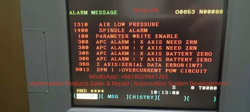
- CNC alarms simultaneously show:
- 9051 SPN: LOW VOLT DC LINK
- 433 X/Y/Z AXIS: CNV LOW VOLT DC LINK
- Multiple spindle, APC, and serial communication alarms
Many technicians immediately suspect parameter mismatch, communication wiring, or controller incompatibility. However, a deeper engineering analysis shows that the root cause lies in the power system, not the CNC controller itself.

2. FANUC CNC Power Architecture: Why DC Link Matters
To correctly diagnose this type of failure, it is essential to understand FANUC’s power structure.
In a typical FANUC 0i-MC system with α or β series drives:
- The PSM / SPM (Power Supply Module / Spindle Power Module):
- Rectifies AC input
- Generates the DC Link (DC Bus)
- The Servo amplifiers (SVU/SVM):
- Share the same DC Link with the spindle module
- The CNC, I/O, and control circuits:
- Depend on stable DC Link status and 24V control power
Key principle:
If the DC Link collapses or becomes unstable, all axes and the spindle will be affected simultaneously. This is why multi-axis low-voltage alarms are extremely significant.

3. Alarm Classification: Root Causes vs. Consequences
The alarms observed in this case can be divided into three logical groups.
3.1 Core Alarms (Root Cause Indicators)
These alarms must be prioritized:
- 9051 SPN 1: LOW VOLT DC LINK
- 433 X / Y / Z AXIS: CNV LOW VOLT DC LINK
- SPM Alarm 24
- SPM Alarm 51
- SPM panel has no LED or display
All of these point directly to DC Link voltage instability or failure.
3.2 Secondary Alarms (Triggered by DC Link Failure)
- 1400 SPINDLE ALARM
- 901 / 9012 SPN: OVERCURRENT POWER CIRCUIT
- 368 / 936 SERIAL DATA ERROR
These alarms typically occur when:
- DC voltage becomes unstable
- Power modules attempt to operate under abnormal conditions
- Internal protection mechanisms are triggered
They are effects, not the primary cause.
3.3 Incidental Alarms (Not Related to the Root Cause)
- 1310 AIR LOW PRESSURE
- 300 APC ALARM: AXIS NEED ZRN
- 306 APC ALARM: BATTERY ZERO
- 100 PARAMETER WRITE ENABLE
These are normal maintenance-related or environmental alarms and should not distract from the main failure analysis.
4. Engineering Interpretation of SPM Alarm 24 and Alarm 51
4.1 SPM Alarm 24: Not Just a Communication Error
SPM Alarm 24 is frequently described as a communication or initialization issue between the CNC and spindle amplifier. While this can be true in isolated cases, it is not the most likely explanation when DC Link alarms are also present.
In real-world service cases, Alarm 24 commonly indicates:
- DC Link pre-charge failure
- DC bus voltage not reaching the required level
- Pre-charge resistor or relay malfunction
- Internal power supply operating at the threshold of failure
In other words, the communication symptom is secondary to a power establishment problem.
4.2 SPM Alarm 51: DC Link Has Entered a Critical State
SPM Alarm 51 explicitly indicates abnormal DC Link voltage conditions.
Typical engineering causes include:
- Aging DC bus capacitors with increased ESR
- Degraded rectifier bridge
- Partially damaged IGBT modules
- Unstable or low AC input voltage
At this stage, the power module is no longer capable of sustaining normal operation.
4.3 SPM Panel Has No LED: Hardware-Level Failure
When the SPM shows no LED or display:
- Internal control power is no longer generated
- Or the power stage has suffered catastrophic failure
This condition is not caused by CNC parameters, software, or wiring order. It indicates internal damage to the SPM module itself.
Repeated power cycling in this state often results in further damage.

5. Why Controller Replacement Appears to Trigger the Failure
This is one of the most misunderstood aspects of such cases.
Before replacement:
- The machine already experienced frequent shutdowns
- The power system was operating in a marginal or degraded condition
After replacement:
- The new CNC controller follows a cleaner, more standardized startup sequence
- Existing weaknesses in the power system are exposed immediately
The CNC controller does not cause the failure; it reveals it.
6. Reconstructing the Complete Failure Chain
From an engineering perspective, the event sequence is typically:
- Power module aging or degraded components
- Difficulty establishing stable DC Link voltage
- SPM Alarm 24 (pre-charge or power establishment abnormality)
- DC Link voltage drops further under load
- SPM Alarm 51 (low DC voltage / power circuit abnormality)
- Servo amplifiers report DC Link low voltage (Alarm 433)
- CNC reports spindle DC Link alarms (Alarm 9051)
- Internal SPM power supply or power stage fails
- SPM panel no longer lights or responds
This sequence matches the observed alarms exactly.
7. Correct Diagnostic Strategy (Avoiding Misguided Repairs)
Step 1: Stop Repeated Power Cycling
Powering the system repeatedly under DC Link fault conditions accelerates damage to IGBTs, rectifiers, and capacitors.
Step 2: Verify 24V Control Power
If 24V control power is present but the SPM remains blank, internal module failure is highly likely.
Step 3: Inspect the DC Bus Physically
- DC bus bars
- High-current connectors
- Contactors and fuses
- Signs of overheating or loose connections
Step 4: Identify Exact Module Models
Recording the A06B-XXXX part numbers allows determination of:
- Repair feasibility
- Replacement options
- Compatibility with the CNC system generation
8. Repair and Recovery Recommendations
- Address the power modules first
- SPM and PSM should be evaluated before any CNC parameter work
- Assess the entire DC Link system
- Power supply, bus wiring, and shared loads
- Restore stable power conditions
- Only then address APC alarms, batteries, and zero return
- Verify parameters and communication last
This order minimizes downtime and prevents unnecessary part replacement.
9. Common Misdiagnosis Pitfalls
- Assuming controller replacement is the root cause
- Treating communication alarms as primary failures
- Ignoring the significance of multi-axis DC Link alarms
- Continuing to power a system with a non-responsive SPM
Avoiding these mistakes can save significant repair cost and time.
10. Conclusion
In FANUC CNC systems, the combination of:
- SPM alarms
- Multiple axes reporting DC Link low voltage
- Frequent CNC shutdowns or OFF conditions
Almost always points to DC Link and power module failure, not CNC software or parameters.
Understanding the system-level power architecture and alarm relationships is the key to accurate diagnosis, efficient repair, and long-term system stability.
SEO Keywords (Naturally Integrated)
FANUC CNC
FANUC Series 0i-MC
SPM Alarm 24
SPM Alarm 51
LOW VOLT DC LINK
FANUC spindle power module failure
FANUC DC bus fault
CNC controller replacement alarms
FANUC CNC power supply troubleshooting