
Abstract
In the field of industrial drives, the ABB ACS550 is widely praised for its excellent stability. However, when many engineers attempt to switch the control mode from traditional Scalar Control to Vector Control, they often encounter alarms such as 2025 (First Start), 2019 (ID Run Waiting), and 2825 (Identification Failed). This article will deeply analyze the underlying logic of these phenomena, combined with actual test data, to provide a standardized debugging process and a pitfall avoidance guide, helping readers achieve precise motor torque and speed control.
I. Introduction: Why Do We Need to Move from Scalar to Vector?
In the primary application of inverters, Scalar Control (V/f Control) is the default choice. Its principle is to keep the ratio of voltage (V) to frequency (f) constant. This mode is like “driving blind”; the inverter does not truly understand the real-time state of the motor. As long as a frequency is given, it outputs the corresponding voltage.
However, when application scenarios involve low-speed high-torque (such as cranes, extruders) or require extremely high dynamic response speeds (such as synchronous processing), the disadvantages of scalar control—insufficient low-speed torque and large speed fluctuations—are exposed. At this point, Vector Control becomes the inevitable choice. Through coordinate transformation, vector control decomposes the stator current into excitation current and torque current components, realizing the control of an AC asynchronous motor like a DC motor.
But vector control is a double-edged sword: it requires an extremely precise motor mathematical model. This is why a series of alarms follow when you modify parameter 9904 (Motor Control Mode).
II. Key Parameters: The Cornerstone of Building the Motor Mathematical Model
Before entering vector control mode, the “genetic information” of the motor must be entered in the 99xx parameter group. If the information is incorrect, the subsequent ID Run (Motor Identification) is destined to fail.
2.1 9905 – 9907: Basic Rated Data
These parameters must be strictly entered according to the motor nameplate.
- 9905 (Voltage): Rated voltage.
- 9906 (Current): Rated current. Note: If the input current is much smaller than the inverter’s rated current, it may cause the identification current to be too small and trigger an error.
- 9907 (Frequency): Usually 50Hz or 60Hz.
2.2 9908: The “Soul” Parameter of Vector Mode — Rated Speed
This is the most error-prone area. In scalar mode, the inverter does not care much about slip; but in vector mode, the inverter must know the motor’s rated speed.
- Wrong approach: Input synchronous speed (e.g., 1500 rpm for a 4-pole motor).
- Correct approach: Input the rated speed with slip (e.g., 1440 or 1460 rpm). If this value is filled in incorrectly, the rotor magnetic field position calculated by the inverter will be offset, resulting in a 2825 alarm.
III. Deep Decoding: The Logic Chain of 2019, 2825, and 2025 Alarms
When you change 9904 to vector mode and set 9910 (ID RUN) to 1, the inverter enters a special logic state.
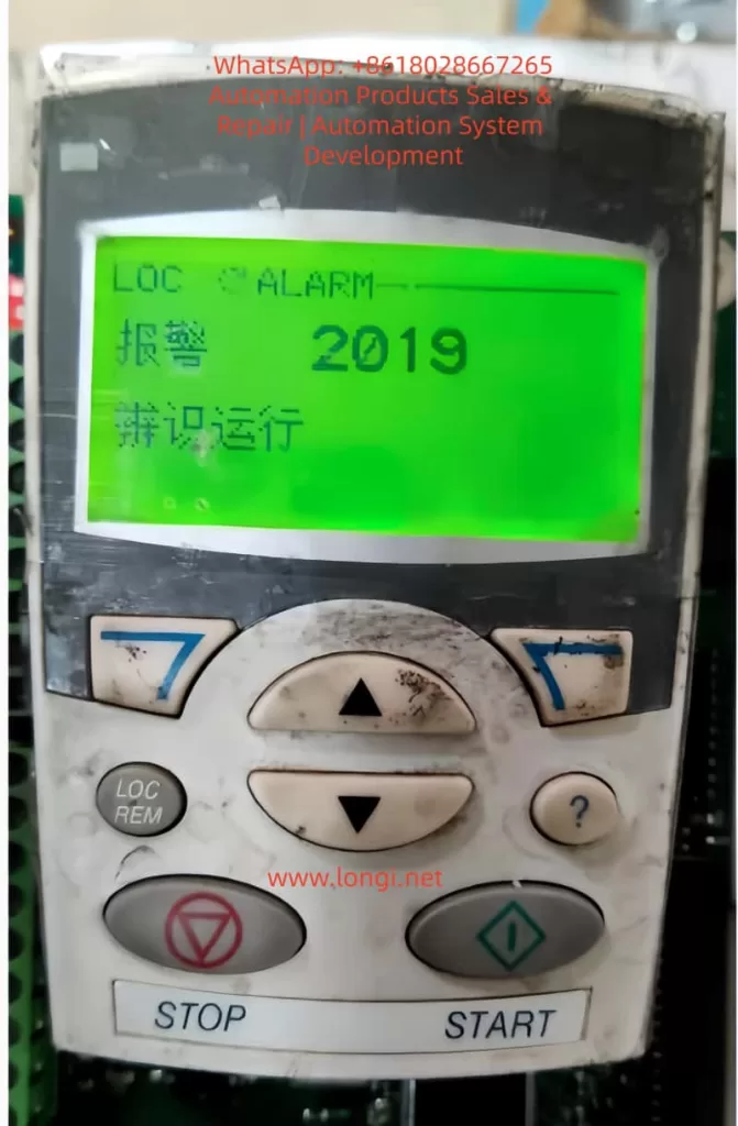
3.1 2019 Alarm: It is Not a Fault, but a “Request”
The screen flashes 2019 (ID RUN), which means: “I am ready to perform motor identification, but for safety, I need you to manually press the Start button to confirm.” At this point, the inverter is in standby mode. Only by pressing the START button on the panel will the identification program actually inject current into the motor.
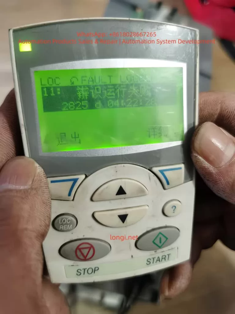
3.2 2825 Alarm: Why Does Identification Fail?
If 2825 (ID RUN FAIL) pops up during the identification process, it usually implies the following situations:
- Load Interference: Standard identification (ID Run 1) requires the motor shaft to rotate without load. If connected to a reducer or high-inertia load, the motor cannot reach the predetermined response, and the identification will be interrupted.
- Brake Not Released: For motors with electromagnetic brakes, the brake must be forced open during identification; otherwise, the motor stall will cause abnormal current.
- 9908 Speed Setting Deviation: As mentioned above, unreasonable speed input will cause the model calculation to fail to converge.
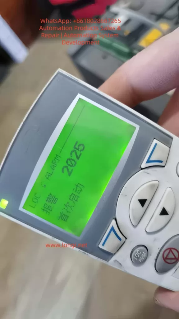
3.3 2025 Alarm: The System’s “Coming of Age”
2025 (FIRST START) is a unique logic of the ACS550. When you change the core control mode (scalar to vector), the system treats this as a “rebirth.” 2025 reminds you: the current model is new and requires a complete start cycle to establish the operating benchmark.
IV. Practical Summary: An Effective Debugging Process
Based on experimental tests, we have summarized a “Golden Process” for ACS550 vector switching:
1. Parameter Alignment:
First, in scalar mode, input the 99xx group parameters accurately according to the nameplate, especially 9908 (actual rated speed, not synchronous speed).
2. Trigger Identification:
- Set 9904 to Vector Mode.
- Set 9910 to 1.
- At this time, the screen flashes 2019.
3. Execute Identification:
- Ensure the motor shaft is in a safe state and press START.
- Observe the motor: It will emit a high-frequency whine (injecting detection current) and may rotate for a short time.
- Key Point: After identification is complete, 9910 will automatically roll back to 0.
4. The “Cycle Method” to Eliminate 2025:
- After identification, if a 2025 alarm appears, do not panic.
- Perform a no-load run, then power off completely. Wait for the panel light to go out and then power on again.
- Run again; the inverter will formally write the identification data from RAM to EEPROM, the alarm will disappear, and the control logic will close the loop.
V. Advanced Optimization: Dynamic Fine-Tuning in Vector Mode
Eliminating alarms is just the beginning. To unleash the power of vector control, you also need to pay attention to the following parameters:
- Group 23 (Speed Compensation): If you find that the speed drops after the motor is loaded, you can improve the dynamic stiffness by adjusting the speed controller Proportional Gain and Integration Time in Group 23.
- Group 20 (Limit Settings): In vector mode, the inverter is more sensitive to overcurrent and overspeed. It is necessary to reasonably set 2003 (Maximum Current) and 2008 (Maximum Speed).
VI. Conclusion
The 2025 and 2019 alarms of the ABB ACS550 are not system defects but rigorous motor protection and self-learning mechanisms. By understanding the logic chain of “Parameter Input -> Trigger 2019 Identification -> Exclude 2825 Interference -> Eliminate 2025 via Run Cycle”, engineers can calmly upgrade the drive system to high-performance vector control status.
Technical Tip:
Never ignore every number on the nameplate. In the world of inverters, the difference of a few dozen RPM in 9908 (Rated Speed) is often the dividing line between “normal operation” and “alarm failure.”