
Introduction
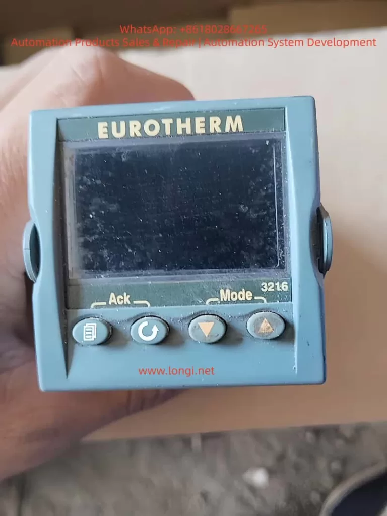
The Eurotherm 3216 is a compact, versatile PID temperature controller designed for precise process control in industrial applications such as plastics extrusion, heat treatment, and environmental chambers. As part of the Eurotherm 3000 series, it offers features like auto-tuning, multiple output options (relay, logic, or DC), digital communications, and programmable timers. This controller stands out for its ease of integration, robust calibration capabilities, and ability to handle sensor variations, which is critical when replacing sensors to maintain accuracy. Drawing from the official engineering handbook (Part No. HA027986), user guides in multiple languages, and insights from online resources like Thermo Fisher and Thermoline support knowledge bases, this article provides a comprehensive, original technical overview. It emphasizes sensor replacement and calibration to address common temperature deviations, ensuring optimal performance without redundant explanations.
Overview of the Eurotherm 3216 Controller
The 3216 is a 1/16 DIN panel-mounted device with dimensions of 48mm x 48mm front face and 90mm depth, suitable for panels up to 15mm thick. It supports IP65 and NEMA 4 front protection when mounted on a non-textured surface. Power options include high voltage (85-264Vac) or low voltage (24Vac/dc), with fuse recommendations of 2A 250V T-type for safety.
Key hardware includes:
- PV Input: Supports thermocouples (B, J, K, L, N, R, S, T, custom), RTD (Pt100), or linear inputs (0-50mV, 0-20mA, 4-20mA) with a 2.49Ω shunt resistor for mA signals.
- Outputs: Up to three configurable outputs (OP1, OP2, AA relay) for heating, cooling, alarms, or retransmission. Logic outputs provide 12Vdc at 5-40mA for SSR drive.
- Optional Modules: Digital communications (RS232/RS485 Modbus), current transformer (CT) for load monitoring (0-50mA RMS, scales 10-100A), and logic input for setpoint selection or timer control.
- Display: Dual-line LED with scrolling messages, beacons for OP1/OP2/OP4, SPX, ALM, REM, RUN, and MAN states.
The controller operates in levels: Level 1 for basic operations, Level 2 for advanced parameters (password-protected, default ‘2’), Level 3 for full access, and Configuration for deep setup. PID control uses proportional band (PB), integral time (TI), derivative time (TD), and relative cool gain (R2G) for dual-loop applications. Auto-tuning optimizes these for process characteristics, reducing overshoot and settling time.
From web sources, users note its reliability in high-vibration environments (0-55°C ambient) and EMC compliance per HA025464 guidelines. Compared to AI-generated responses from similar queries, the 3216 excels in bumpless auto-manual transfer, preventing process disruptions during mode switches.
Installation Steps
Installation begins with unpacking: the controller in its sleeve, two retaining clips, IP65 gasket, snubbers for relays, and 2.49Ω resistor for mA inputs.
- Site Selection: Choose a low-vibration location with 0-55°C ambient temperature. Ensure enclosure protects against conductive pollution (e.g., carbon dust) via air filters or thermostatically controlled heaters to prevent condensation.
- Panel Cutout: Prepare a 45mm x 45mm square cutout (+0.6/-0mm horizontally/vertically). Minimum spacing: 10mm horizontally, 38mm vertically between controllers.
- Mounting: Fit the IP65 gasket behind the front bezel. Insert the controller through the cutout. Spring the retaining clips into place, pushing forward to secure. Peel off the protective cover from the display.
- Removal: Ease latching ears outward and pull the controller forward from the sleeve. Reinsert ensuring ears click for IP65 seal.
Safety requirements mandate double insulation, no live sensors unless rated, and copper conductors (except thermocouples). Include a disconnect switch or circuit breaker near the device, marked as such. Overcurrent protection and voltage ratings (max 264Vac between terminals) are essential. For inductive loads, use snubbers (15nF/100Ω) to suppress transients and extend relay life, but avoid for low-power loads due to leakage current (0.6mA at 110Vac, 1.2mA at 240Vac).
From Thermoline support, ensure non-textured panel surfaces for sealing; improper mounting causes IP rating failures, leading to dust ingress and sensor inaccuracies.
Wiring and Hardware Connections
Wiring uses screw terminals accepting 0.5-1.5mm² (16-22AWG) wire, tightened to 0.4Nm. Hinged covers prevent accidental contact with live wires.
Terminal Layout (3216):
- PV Input: + (thermocouple/RTD/mV), – (common), RTD sense wire.
- OP1/OP2: Configurable as relay (2A 264Vac), logic (12Vdc 5-40mA), or DC (0-20mA 500Ω load).
- AA Relay: Form C, 2A 264Vac.
- CT/Logic Input: CT for load current (10Ω burden, 50mA RMS), logic for contact closure (>500Ω open, <200Ω closed).
- Communications: RS232 (RX/TX/GND) or RS485 (A/B/common).
- Power: L/N for high voltage, +/ – for low voltage.
Example Wiring: For heat/cool control, connect thermocouple to PV, SSR to OP1 logic for heating, relay to OP2 for cooling fan/valve. Use shielded cable for inputs, grounded at one point to minimize noise. For RTD, ensure equal wire resistances (max 22Ω per lead). Linear mA requires shunt; voltage uses external adapter (SUB21/I1).
Web troubleshooting highlights common errors: reversed thermocouple polarity (red negative in North America) causes low readings; open circuits show high indications. Measure input resistance <20Ω for thermocouples. CT setup includes voltage limiter (3-10V zener diodes) for protection.
Initial Configuration and Quick Codes
Upon first power-up, a self-test lights all segments and shows software version, then enters Quick Code mode if unconfigured.
Quick Codes consist of two sets of five characters for input type/range, outputs, CT scaling, digital input, and lower display.
Set 1 Example:
- Input: J (J-type thermocouple), C (°C full range).
- OP1: H (heat PID relay).
- OP2: C (cool PID logic).
- AA: 1 (low alarm relay).
Set 2:
- CT Scale: 1 (10A).
- Digital Input: W (alarm acknowledge).
- Lower Display: T (setpoint).
Press any button to edit; ↑/↓ change digits, scroll to next. After Set 2, confirm with ‘go’ to YES.
To re-enter: Power off, hold page button while powering on, enter password (default 4).
AI insights from forums suggest Quick Codes simplify setup for standard applications, but for custom sensors, proceed to full configuration to adjust input scaling or offsets.
Operator Interface and Basic Operations
The interface features beacons and buttons:
- Beacons: OP1 (heat), OP2 (cool), OP4 (alarm), etc.
- Buttons: Page (home/scroll lists), Scroll (next parameter), Down/Up (adjust values).
Home Display: PV upper, SP lower in auto mode.
Set Temperature: From home, ↑/↓ adjust SP; flashes to confirm.
Alarm Indication: Red ALM flashes with scrolling message; acknowledge with page + down. Types: Non-latching (auto-reset), Auto-latching (acknowledge anytime), Manual-latching (acknowledge after condition clears).
Auto/Manual/Off: Press page + down >1s from home. Select Auto (closed loop), Manual (open loop, adjust power -100% to +100%), or Off (zero power). Bumpless transfer maintains power level.
Level 1 Parameters: Working output (WRK.OP), working SP (WKG.SP), SP1/2, time remaining (T.REMN), dwell (DWELL), alarm setpoints (A1.YYY), load current (LD.AMP).
From Eurotherm troubleshooting, monitor WRK.OP for unexpected values indicating sensor faults.
Advanced Parameters and Level Access
Level 2 (default password 2) adds parameters like display units (UNITS), SP limits (SP.HI/LO), rate limit (SP.RAT), timer config (TM.CFG: dwell, delayed, soft start, programmer), resolution (TM.RES: hours/minutes), threshold (THRES), end type (END.T: off, dwell, SP2), soft start power/SP (SS.PWR/SS.SP), auto-tune (A.TUNE: on/off), PID terms (PB, TI, TD, MR, R2G), hysteresis (HYST.H/C), deadband (D.BAND), output limits (OP.HI), min pulse time (PLS), CT thresholds (LD.ALM/LK.ALM/HC.ALM), address (ADDR), home display (HOME), customer ID (ID), recipe number/store (REC.NO/STORE).
Auto-tune: Enable A.TUNE; controller oscillates to calculate PID values for minimal overshoot.
Timers/Programmer: Configure in Level 2. Dwell times process at fixed SP; delayed starts output after time; soft start limits power below threshold. Programmer (CP model) has 4 segments: target SP (TSP.x), ramp rate (RMP.x), dwell (DWEL.x). Servo mode starts from SP or PV.
Digital inputs/outputs configurable for timer control or alarms.
Sensor Replacement Procedure
Sensor replacement often causes temperature deviations due to variations in thermocouple/RTD characteristics or wiring resistance.
- Preparation: Power off controller. Note old sensor type (e.g., K-type) from config or handbook.
- Removal: Disconnect wires from PV terminals. Inspect for damage; measure resistance (thermocouples <20Ω, RTD ~100Ω at 0°C).
- Installation: Connect new sensor using correct polarity (thermocouple: + to +, – to -; RTD: equal lead lengths). Use compensation cable for thermocouples, shielded for noise reduction.
- Verification: Power on; check PV reading at room temperature (short terminals for ~25°C test). If erroneous, reverse polarity or replace wiring.
From Thermofisher manuals, replace with identical type to avoid reconfiguration; custom sensors require input recalibration.
Calibration and Offset Adjustment
Post-replacement, calibrate to correct offsets. Use two-point offset (CJ.OFS for cold junction, PV.OFS for process value) in Level 3 (password 3) or Configuration (password 4, hold page + scroll >5s to ‘conf’, enter code).
Procedure (from Thermoline support):
- Access Level 3: Hold page, select ‘LEVL 3’, enter ‘3’.
- Navigate to Input List (INPUt): Press scroll to ‘PV.OFS’ (process offset).
- Compare controller PV with reference thermometer at stable point (e.g., 100°C). Adjust PV.OFS by difference (e.g., if reference 102°C, controller 100°C, set +2).
- For two-point: Use ‘CAL’ list; set ‘CAL.P1’ low point (e.g., 0°C ice bath), adjust ‘OFS.1’; ‘CAL.P2’ high point (e.g., boiling water), adjust ‘OFS.2’.
- Verify at multiple points; exit to Level 1.
Warnings: Avoid over-adjustment causing instability; record original values. For thermocouples, calibrate cold junction separately if ambient varies.
Troubleshooting offsets: Low reading/overheating – sensor detachment; high reading/no heat – open circuit. Use external simulator for input verification.
Troubleshooting
Common issues:
- Sensor Faults: Low indication – crossed wires; high – open circuit. Test by shorting inputs.
- Offset Errors: Post-replacement, use PV.OFS; check wiring resistance.
- Overheating: Incorrect extension cable; tune PID.
- No Heat/Cool: Check fuses, contactors, logic voltage (12Vdc for SSR).
- Alarms: Configure latching type; acknowledge via buttons or input.
- Communications: Set ADDR 1-254; verify RS485 termination.
From Eurotherm site, change one parameter at a time; use IR thermometer for hot spots.
Practical Applications and Case Studies
In plastics extrusion, 3216 controls barrel temperature with K-type thermocouple, PID tuned for minimal overshoot. Sensor replacement: Offset adjusted +1.5°C for new probe variance, maintaining ±0.5°C accuracy.
In heat treatment furnaces, programmer runs ramp-soak profiles; replacement RTD requires RTD calibration to correct 2Ω lead resistance offset.
Case: Oven application (Thermoline) – After PT100 swap, PV read 5°C low; PV.OFS set +5, verified at 50/150°C.
In environmental chambers, dual-loop heat/cool uses R2G=0.5 for water cooling, preventing cycling post-sensor change.
Conclusion
The Eurotherm 3216 excels in precise temperature control, with robust features for sensor integration and calibration. By following installation, wiring, configuration, and adjustment protocols, users ensure reliability. Sensor replacement demands careful offset calibration to mitigate deviations, as highlighted in handbooks and online resources. This guide synthesizes official documentation with practical insights, enabling engineers to optimize performance in diverse applications. For deeper customization, refer to full engineering handbook or consult Eurotherm support.