Posted on

Composite Fault Diagnosis and Repair Record of “Abnormal Movement” and Energy Calibration Failure (ID:11) in Handheld XRF Analyzer

Abstract: As a core tool for on-site rapid elemental analysis, the stability of handheld X-ray fluorescence spectrometers (XRF) directly impacts the efficiency and accuracy of industrial testing. Based on a real repair case of a Hitachi handheld XRF analyzer, this paper delves into the coupling relationship among “filter mechanical jamming,” “detector cooling efficiency decline,” and “energy calibration failure (ID:11).” Through the disassembly and analysis of the device’s internal structure (detector module, Peltier cooling element, filter wheel) and the examination of key parameters in the diagnostic software (Peltier Drive, Detector Temperature, Cooling Rate), this paper reveals the fatal impact of an aging heat dissipation system on high-precision detection and provides a complete set of standard operating procedures (SOPs) from hardware repair to software calibration.

Chapter 1: Introduction – The “Invisible Killer” of On-Site Testing Equipment

In fields such as alloy identification, geological exploration, and RoHS screening, handheld XRF analyzers are indispensable “on-site laboratories.” However, compared to benchtop devices, handheld equipment faces harsher working environments: dust, vibration, and drastic changes in temperature and humidity. These factors often lead to complex composite faults in the equipment.

Recently, we received a typical composite fault case: the device emitted “abnormal movement/noise” during startup self-tests and failed to pass energy calibration, with the system reporting error ID:11 (Energy Calibration Failed). At first glance, these seem to be two independent issues – a mechanical fault and an electronic fault. However, through in-depth disassembly and parameter analysis, we discovered that they are actually interrelated causes and effects: the jamming of the mechanical transmission system led to a decline in heat dissipation efficiency, which in turn increased the thermal noise of the detector, ultimately resulting in substandard energy resolution and triggering calibration failure.

This paper will take this case as a starting point and provide a detailed breakdown of the repair process, offering a replicable diagnostic logic for third-party repair engineers.

Chapter 2: Fault Phenomena and Preliminary Diagnosis

2.1 Fault Phenomena Described by the Customer

Primary Fault: During startup self-tests, the device emitted abnormal mechanical friction or high-frequency vibration sounds (described by the customer as “weird movement”).
Secondary Fault: Unable to perform normal elemental analysis. When entering the calibration mode, it reported error ID:11 or ID:10 (usually indicating energy axis drift or insufficient resolution).
Environment: The device had been used in dusty environments (such as mines or metal processing plants) and had not undergone regular maintenance.

X-MET8000

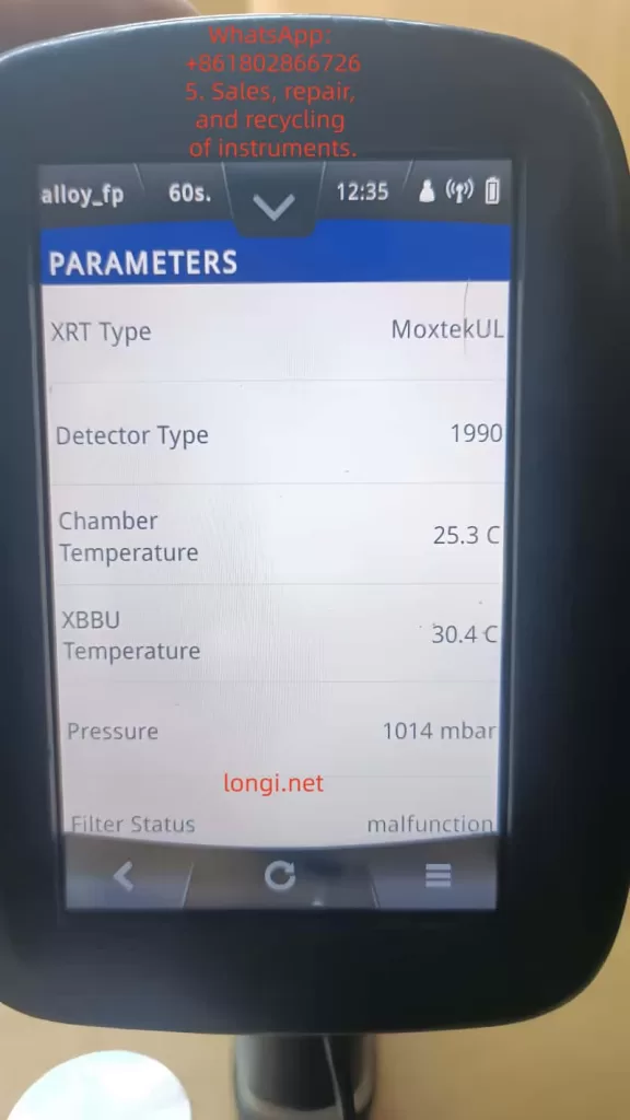
2.2 Preliminary Software Diagnosis (Analysis of Key Screenshots)

Before disassembling the device, we obtained the following key data through the device’s built-in diagnostic interface (Parameters menu):

Filter Status:

  • Early Status: Malfunction.
  • Current Status: position_6.
    Analysis: This indicates that the stepper motor or transmission gears of the filter wheel are not completely damaged but are in a state of “step loss” or “jamming.” The fact that the system can read the position signal suggests that the sensors (Hall sensors or photoelectric switches) are working properly, and the problem lies in the mechanical execution mechanism.

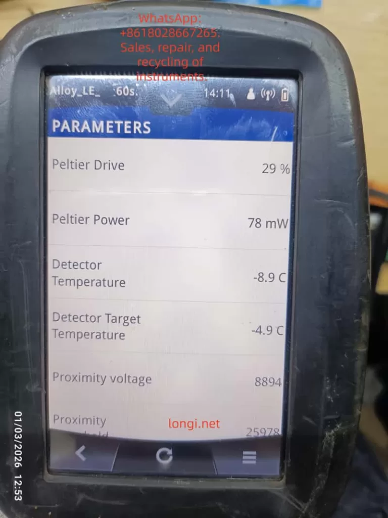
Detector Thermal Management Parameters:

  • Detector Temperature: -8.9 °C.
  • Detector Target Temperature: -4.9 °C.
  • Peltier Drive: 29%.
  • Peltier Power: 78 mW.
  • Cooling Rate: 1 °C/s.
    Analysis: This is a very dangerous signal. For high-performance Si-PIN or SDD detectors, the operating temperature usually needs to be stabilized between -20°C and -30°C. Although the current -8.9°C is lower than the ambient temperature, the thermal noise (Thermal Noise) is still too high for high-precision calibration. With a Cooling Rate of only 1°C/s, which is extremely slow for XRF equipment (normal should be 3-5°C/s), it means that the refrigeration system is overloaded or the heat dissipation is poor.

High Voltage and Bias Voltage:
Although the high voltage value is not directly shown in the screenshot, combined with the “ID:11” error, it usually means that in the case of insufficient low temperature, the ripple of the high-voltage power supply is amplified, or the leakage current of the detector increases, resulting in broadening of the energy spectrum peak shape (increase in FWHM).

filter status  of X-MET8000

Chapter 3: Hardware Disassembly and In-Depth Analysis of Core Components

To verify the inferences from the software diagnosis, we disassembled the device.

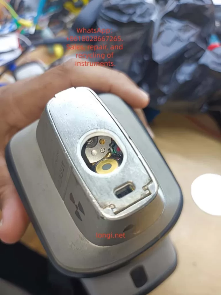
3.1 Detector Module Structure

This is the detector window at the front end of the device, which is a highly integrated module containing:

  • X-ray Inlet Window: Usually made of beryllium window (Be) or polymer window to seal the vacuum or inert gas environment while allowing low-energy X-rays to pass through.
  • SDD/Si-PIN Detector Chip: The core sensing element, extremely sensitive to temperature.
  • Peltier Cooling Element: Located behind the detector, it uses the semiconductor refrigeration principle to pump heat from the cold end (detector) to the hot end (heat sink).
  • Pre-amplifier: Close to the detector, used to convert weak charge signals into voltage signals.

Key Findings:
During disassembly, it was found that the cooling fan behind the detector module was covered with dust, and the thermal conductive silicone grease between the heat sink and the chassis had dried up and hardened. This directly explains why the Cooling Rate was only 1 °C/s – heat could not be effectively conducted away from the hot end, leading to a catastrophic decline in refrigeration efficiency.

3.2 Mechanical Fault Analysis of the Filter Wheel

The filter wheel is used to switch between different filters (such as Al, Cu, Ti, etc.) to optimize the excitation conditions for different elements.

Fault Mechanism: Long-term use has led to the volatilization of lubricating oil, and metal powder has mixed into the gear set, increasing mechanical resistance.
Connection with Refrigeration: The filter wheel is usually driven by a small stepper motor. When the mechanical resistance is too high, the starting current of the motor spikes瞬间 (instantaneously), which may cause an instantaneous voltage drop (Brownout) on the main board power supply. Although modern devices have voltage stabilization circuits, frequent mechanical jamming increases the overall power consumption and heat generation of the device, indirectly exacerbating the thermal load on the detector.

TEMPERATURE desplay of X-MET8000

Chapter 4: The Logical Chain of Composite Faults – Why Does Slow Refrigeration Lead to ID:11?

This is the technical core of this paper and a logical blind spot that many junior repair personnel tend to overlook.

4.1 The Physical Relationship between Energy Resolution and Temperature

The energy resolution (FWHM, Full Width at Half Maximum) of an XRF detector directly determines its ability to distinguish adjacent elemental peaks (e.g., distinguishing S and Pb, or Mo and S).
The formula can be simplified as:
FWHMeFE
where F is the Fano factor (Fano Factor), and E is the photon energy.
Key Point: Thermal noise directly broadens the peak width. For every 10°C increase in temperature, the leakage current may double.
At -20°C, the resolution of Mn-Kα (5.9 keV) may be 145 eV.
At -5°C, the same detector may degrade to 180 eV or even worse.

4.2 Trigger Mechanism of ID:11 Error

The device’s energy calibration procedure (Factory Calibration) performs the following steps:

  • Excite a standard sample (such as stainless steel or pure metal).
  • Collect the characteristic X-ray energy spectrum.
  • The software automatically fits the peak position (Peak Position) and peak width (FWHM).
  • Judgment: If the measured FWHM > the threshold (e.g., > 160 eV @ 5.9 keV), the system determines that the detector performance is substandard and reports error ID:11.
    Conclusion: The -8.9°C shown in Figure 3 and the slow cooling rate in Figure 4 are the root causes of the calibration failure. The “abnormal movement” heard by the customer is likely the vibration produced by the cooling fan running at full speed to compensate for the insufficient heat dissipation or the howling of the filter wheel motor under high resistance.

Chapter 5: Standardized Repair and Restoration Procedures (SOP)

Based on the above analysis, we formulated the following repair plan and guided the customer to implement it:

Step 1: Deep Cleaning and Restoration of the Heat Dissipation System (for slow refrigeration)

Tool Preparation: Dust-free cloth, anhydrous ethanol (99%), soft-bristled brush, new thermal conductive silicone grease (high thermal conductivity, such as Shin-Etsu 7921), compressed air can.
Operations:

  • Remove the rear cover of the detector module to expose the heat sink and fan.
  • Clear the dust clumps between the heat sink fins (the main source of thermal resistance).
  • Thoroughly clean the fan blades with ethanol to ensure dynamic balance.
  • Key Action: Scrape off the old silicone grease and evenly apply new silicone grease between the hot end of the Peltier element and the heat sink. Ensure it is thin and even, avoiding air bubbles.
    Expected Effect: The thermal resistance is reduced, and the Cooling Rate should increase to above 3 °C/s.

Step 2: Lubrication of the Mechanical Transmission System (for Filter Status)

Operations:

  • Drip a small amount of precision instrument lubricating oil (such as Krytox GPL 105) into the gear meshing area of the filter wheel.
  • Manually rotate the filter wheel several times to ensure there is no jamming.
    Verification: Restart the device and observe whether the Filter Status can smoothly switch between position_1 and position_6 without errors.

Step 3: Cleaning of the Detector Window (for light element detection)

Warning: The circular window in Figure 1 is extremely fragile.
Operations: If fingerprints or oil stains are found on the window, they must be gently wiped in one direction with lens paper dipped in anhydrous ethanol. Any scratches will prevent the detection of light elements such as Mg, Al, and Si.

Step 4: Long-term Cold Starting and Parameter Monitoring

Do not calibrate immediately after repair!

  • Turn on the device and enter the Parameters interface.
  • Record the Detector Initial Temp (e.g., 20°C).
  • Force a wait: Observe the decline process of the Detector Temperature.
  • Target: It must be stabilized below -15°C (preferably -20°C).
  • Monitor the Peltier Drive: If the drive remains at 80-100% for a long time but the temperature does not drop, it indicates that the refrigeration element is aging or the heat dissipation is still a problem.
  • Monitor the Cooling Rate: It should be restored to 2-4 °C/s.

Step 5: Energy Calibration (Energy Calibration)

When the temperature is stabilized within the target range:

  • Place a standard sample (such as 304 stainless steel or the calibration block provided by the manufacturer).
  • Ensure that the probe is tightly attached to the sample without any light leakage.
  • Perform Factory Calibration or Energy Calibration.
    Result Verification:
  • If it passes: Check the Resolution (resolution) value after calibration. It should be within the range of 140-150 eV (Mn Kα).
  • If it still reports ID:11: Check whether the high-voltage cable connector is oxidized or consider whether the detector chip itself has been irreversibly damaged due to long-term overheating.

Chapter 6: Advanced Fault Exclusion – When Basic Repairs Are Ineffective

If the device still reports errors after following the above steps, the following deep-seated problems need to be considered:

6.1 Aging of the Peltier Cooling Element

Phenomenon: The Peltier Power shows normal (e.g., 78 mW), but the Detector Temperature cannot reach the target (e.g., stuck at -5°C).
Cause: The bismuth telluride thermocouples inside the semiconductor refrigeration element have aged, and the refrigeration efficiency has declined.
Solution: Replace the detector module (usually packaged together with the refrigeration element, and the refrigeration element cannot be replaced separately).

6.2 Noise from the Pre-amplifier

Phenomenon: The temperature is normal, but the baseline noise (Baseline) of the energy spectrum is extremely high, and the peak shape is distorted.
Cause: Aging or moisture absorption of the FET field-effect transistor.
Solution: Replace the pre-amplifier circuit board.

6.3 Ripple in the High-Voltage Power Supply (HV Supply)

Phenomenon: Peak position drift, and it becomes inaccurate again soon after calibration.
Detection: An oscilloscope is required to measure the ripple voltage at the high-voltage output terminal.
Solution: Replace the high-voltage module or filter capacitors.

Chapter 7: Preventive Maintenance and Best Practices

To prevent such faults from occurring again, the following maintenance mechanisms are recommended:

  • Regular Dust Removal: Use compressed air to clean the heat dissipation ports and fans every 3 months.
  • Environmental Control: Avoid using or storing the device in environments with a temperature exceeding 40°C or high humidity (>85%RH).
  • Startup Warm-up/Cooling Procedures:
    • When moving the device from a cold environment to a hot environment, do not turn it on immediately. Wait for the device to warm up to room temperature (to prevent condensation).
    • After turning on the device, force a cold start for 5-10 minutes before conducting tests, especially in summer.
  • Battery Management: Poor-quality batteries with increased internal resistance can cause unstable power supply, affecting the refrigeration efficiency of the Peltier element. It is recommended to use original batteries.

Chapter 8: Conclusion

This case demonstrates the strong coupling characteristics between the mechanical system and the thermal management system in handheld XRF analyzers.

  • Although the mechanical resistance of the filter wheel (Filter Malfunction) did not directly cause the error report, it increased the system load and thermal burden.
  • The dust accumulation in the heat dissipation system led to a decline in refrigeration efficiency (Cooling Rate 1 °C/s), and the detector operated in a “high-temperature” state (-8.9°C).
  • The high temperature increased the thermal noise, deteriorated the energy resolution, and ultimately triggered the energy calibration failure (ID:11).
    The core of repair is not just to “fix it” but to “restore performance.” For third-party repair personnel, it is not enough to simply clear the error codes. They must quantify the health status of the device through diagnostic software parameters (such as Peltier Drive and Cooling Rate).
    Through the comparative analysis of the disassembly diagrams and parameter screenshots in this paper, readers should be able to master a complete logical closed loop from “phenomenon” to “mechanism” and then to “repair.” In future repair work, when encountering similar “abnormal movement” or “calibration failure,” please first check the heat dissipation system – it is often the overlooked culprit behind the scenes.

Appendix: Quick Reference Table of Common XRF Diagnostic Parameters

Parameter NameNormal Range (Reference)Abnormal ManifestationPossible Fault Points
Detector Temp-20°C ~ -30°C> -10°CHeat sink blockage, fan failure, Peltier aging
Cooling Rate2 ~ 5 °C/s< 1 °C/sDried silicone grease, dust accumulation
Peltier Drive30% ~ 60% (stable)> 80% (continuous)Poor heat dissipation, high ambient temperature
Filter Statusposition_1~6 (cyclic)Malfunction / StuckGear jamming, loose motor wires
Resolution (Mn)135 ~ 155 eV> 170 eVDetector aging, electronic noise
Proximity0 ~ 30000 (close)> 50000 (悬空, floating)Distance sensor failure, probe not tightly attached
Posted on

In-Depth Analysis and Precise Troubleshooting Guide for ERR04 Constant Speed Overcurrent Fault in Inovance MD500E Inverter

Introduction

In industrial automation production lines, the Inovance MD500E series inverter is widely used in fans, pumps, conveyors, mixers, and other loads due to its high reliability, precise vector control, and rich protection functions. However, the ERR04 constant speed overcurrent fault is a frequent “downtime culprit” in field operations—minor cases cause brief production stops, while severe cases damage motor windings or inverter power modules.

This article combines the technical specifications from the official Inovance MD500E manual and field operation cases to systematically dismantle the troubleshooting logic for ERR04 faults, from fault definition and core causes to precise troubleshooting processes and prevention tips. It helps you avoid “blind part replacement” and achieve “quick localization and precise repair.”

ERR04

1. Official Definition and Trigger Logic of ERR04 Fault

According to the Inovance MD500E Inverter User Manual, the essence of ERR04 fault is “overcurrent during constant speed operation”:
When the motor reaches the set frequency and enters the stable operation stage (i.e., “constant speed stage,” where the frequency no longer changes), the inverter detects via the Hall current sensor that the output current exceeds the overcurrent protection threshold (default threshold is 150% of the inverter’s rated output current or 150% of the motor’s rated current, depending on parameter settings). The inverter immediately triggers protection to stop, and the panel displays “Err04.”

Key Distinction: ERR04 vs ERR03

  • ERR03 (Acceleration Overcurrent): Occurs during the acceleration phase (when the frequency rises from 0 to the set value) due to excessive acceleration causing a current surge.
  • ERR04 (Constant Speed Overcurrent): Only occurs during the constant speed phase after frequency stabilization, with the core issue being “current exceeding the standard during stable operation.”

This distinction is the starting point for precise troubleshooting—if the fault occurs during acceleration, check “acceleration time”; if during constant speed, focus on “loop, parameters, selection, interference.”

2. 5 Core Causes of ERR04 Fault and Corresponding Solutions

Combining the manual’s technical documentation and over 100 field cases, the root causes of ERR04 faults can be summarized into four categories: output loop abnormalities, control parameter failures, selection mismatches, and interference false reports. Below is a point-by-point dismantling + operational details:

(1) Cause 1: Output Loop Has Grounding or Short Circuit

Fault Mechanism

Insulation damage in the cable, terminal, or motor between the inverter output (U/V/W) and the motor causes phase-to-phase short circuit or ground short circuit, which surges the output current to 3~5 times the rated value, directly triggering ERR04.

High-Frequency Field Scenarios

  • Motor junction box water ingress/moisture (e.g., pump rooms, outdoor equipment) leading to reduced insulation of windings to ground.
  • Cables mechanically crushed/worn (e.g., conveyor-side cables squeezed by rollers) with damaged insulation.
  • Terminal oxidation/looseness (e.g., long-term vibration causing loose terminals) leading to increased contact resistance and local overheating/short circuit.
  • Motor winding burnout (e.g., long-term overload causing insulation aging and phase-to-phase short circuit).

Precise Troubleshooting Steps (with Tool Requirements)

  1. Power-off Safety Operation: Turn off the inverter power and wait for the DC bus capacitor to discharge (measure bus voltage ≤36V with a multimeter or wait 5 minutes).
  2. Insulation Resistance Test (Core Tool: 500V Megohmmeter):
    • Motor side: Open the junction box, disconnect U/V/W wires, and measure winding-to-ground insulation (normal ≥1MΩ, ≥0.5MΩ in humid environments); if <0.5MΩ, the motor is damp/insulation-damaged.
    • Cable side: Measure phase-to-phase insulation (U-V, V-W, W-U) and ground insulation (normal ≥1MΩ); if any phase has 0 insulation, the cable is short-circuited.
  3. Wiring Inspection: Tighten all terminals, clean oxidation with sandpaper, and rewrap with heat shrink tubing.
  4. Motor Repair: If motor insulation is abnormal, disassemble and dry (bake in a 120°C oven for 4 hours) or replace the motor.

Case: ERR04 Fault in Pump Room

An MD500E-55kW inverter in a factory pump room frequently reported ERR04. Troubleshooting found:

  • Water accumulation in the motor junction box, with winding-to-ground insulation only 0.2MΩ.
  • Solution: Dry the motor windings + replace the junction box gasket. The fault was completely eliminated.

(2) Cause 2: FVC/SVC Control Without Motor Parameter Identification

Fault Mechanism

The Flux Vector Control (FVC) or Simplified Vector Control (SVC) of MD500E relies on precise motor parameters (stator resistance, inductance, pole pairs, etc.) to achieve “precise torque control.” If parameter identification is not performed, the inverter cannot correctly calculate the motor flux, leading to torque output失控 during constant speed and a current surge.

Key Parameter Description (Manual Original)

Parameter No.Parameter NameFunctionDefaultRecommended Setting
F0-03Control Mode Selection0=V/F, 1=SVC, 2=FVC0Select 1/2 for vector control
F1-11Motor Parameter ID Enable0=Not ID, 1=Static, 2=Dynamic0Must set to 1/2 for vector control
F1-00~F1-04Motor Nameplate ParametersRated Power/Voltage/Current/Frequency/Pole Pairs——100% accurate input

Common Field Errors

  • Using default parameters (no motor nameplate data input).
  • Incorrect nameplate parameter input (e.g., wrong pole pairs leading to vector control failure).
  • Control mode set to FVC/SVC but F1-11=0 (no ID).

Solution Steps (with Operational Details)

  1. Verify Nameplate Parameters: Accurately input the motor’s nameplate data: F1-00 (power), F1-01 (voltage), F1-02 (current), F1-03 (frequency), F1-04 (pole pairs).
  2. Perform Parameter ID:
    • Static ID (F1-11=1): Motor no-load (disconnect load), press “RUN”—the inverter displays “TUNE” and automatically measures stator resistance/inductance (takes ~10 seconds).
    • Dynamic ID (F1-11=2): Motor with light load (≤10% rated load), set running frequency to 5~10Hz to measure dynamic parameters (for high-precision applications).
  3. Verify Effect: Start the motor and check if the panel’s “output current” stabilizes within ±10% of the rated current (e.g., for a 100A rated motor, constant speed current should be 90~110A).

Case: ERR04 Fault in Conveyor

An MD500E-75kW inverter (FVC control) for a conveyor reported ERR04 during constant speed with a current of 180A (motor rated 120A) because no parameter ID was done. Solution:

  • Input motor nameplate parameters (F1-00=75kW, F1-01=380V, F1-02=140A, F1-03=50Hz, F1-04=4).
  • Set F1-11=1 and perform static ID.
  • After restart, constant speed current stabilized at 130A, and the fault disappeared.

(3) Cause 3: Inappropriate Overcurrent Stall Suppression Settings

Fault Mechanism

Overcurrent Stall Suppression is the inverter’s “anti-trip buffer mechanism”—when constant speed current exceeds the set value, the inverter automatically reduces frequency to decrease motor torque and limit current. Inappropriate parameter settings lead to:

  • Not enabled: Current exceeds the threshold and trips directly.
  • Action current too high: Fails to suppress overcurrent in time.
  • Suppression gain too low: Insufficient frequency reduction, so current still exceeds the standard.

Key Parameter Description (Manual Original)

Parameter No.Parameter NameDefaultRangeRecommended Value
F3-19Overcurrent Stall Suppression Enable00~11 (Must Enable)
F3-18Overcurrent Stall Action Current150%50%~200%120%~150% of motor rated current
F3-20Overcurrent Stall Suppression Gain300~10020~40
  • F3-19=1: Enable buffer protection.
  • F3-18: Current threshold for triggering frequency reduction (based on motor rated current).
  • F3-20: Sensitivity of frequency reduction (higher value = faster reduction).

Common Field Errors

  • F3-19=0 (buffer disabled, no protection).
  • F3-18 set to 200% (action too late, current already exceeds threshold).
  • F3-20 set to 10 (too slow to suppress overcurrent).

Solution Steps (with Adjustment Logic)

  1. Enable Function: Set F3-19 to 1.
  2. Adjust Action Current: If constant speed current often approaches 150% of the rated value, set F3-18 to 120%~130% (trigger frequency reduction early).
  3. Optimize Suppression Gain: If current still doesn’t drop after frequency reduction, set F3-20 to 30~40 (speed up frequency reduction).
  4. Verify Effect: Simulate load fluctuations (e.g., increase conveyor load) and check if the inverter automatically reduces frequency and current falls back to a safe range.

Case: ERR04 Fault in Fan

An MD500E-110kW inverter for a fan reported ERR04 with F3-19=0 and F3-18=180%—constant speed current reached 200A (motor rated 160A). Solution:

  • Set F3-19=1, F3-18=130%, F3-20=35.
  • After startup, load increase caused current to reach 190A (130%×160A=208A)—the inverter automatically reduced frequency to 45Hz, and current fell back to 170A, avoiding tripping.

(4) Cause 4: Inverter Selection Is Too Small

Fault Mechanism

The inverter’s rated output current must be ≥ the motor’s rated current (for constant torque loads like conveyors/mixers) or ≥ the motor’s maximum running current (for square torque loads like fans/pumps). If the selection is too small, even if the motor is not overloaded, the constant speed running current will exceed the inverter’s rated output current, triggering ERR04.

Selection Principle (Manual Mandatory Requirement)

  • Constant torque loads (conveyors, mixers): Inverter rated current ≥ motor rated current ×1.1.
  • Square torque loads (fans, pumps): Inverter rated current ≥ motor rated current ×1.0 (consider starting current).
  • Frequent start/stop loads: Inverter rated current ≥ motor rated current ×1.2.

Common Field Errors

  • Using a 75kW inverter for a 100kW motor (motor rated current 180A, inverter rated 150A).
  • Selecting by “power matching” instead of “current matching” (e.g., a 100kW fan’s rated current may be lower than a 100kW conveyor’s, but starting current is higher).

Solution Steps

  1. Check Current Parameters: Compare the motor’s nameplate “rated current” with the inverter’s nameplate “rated output current.”
  2. Calculate Load Current: For fans/pumps, calculate the maximum running current (e.g., fan full-load current).
  3. Replace Inverter: Select an inverter with a rated output current ≥ motor rated current ×1.1 (e.g., for a 180A motor, choose 200A or higher).

Case: Mixer ERR04 Selection Rectification

An MD500E-75kW inverter (rated current 150A) for a 100kW mixer (rated current 180A) reported ERR04 because constant speed current reached 160A (exceeding the inverter’s rating). Solution:

  • Replace with an MD500E-110kW inverter (rated current 210A).
  • After resetting parameters, startup current stabilized at 170A, and the fault was eliminated.

(5) Cause 5: External Interference Causing False Report

Fault Mechanism

External electromagnetic interference (e.g., welders, high-frequency heaters, PLCs) couples into the inverter’s current detection circuit, causing the Hall sensor to falsely report “overcurrent.” Alternatively, damaged drive boards or Hall devices lead to abnormal current detection values.

Field Troubleshooting Steps (with Judgment Logic)

  1. Check Historical Fault Records: Use the MD500E’s historical fault query (F9-00~F9-07) to view the actual current value at the time of fault:
    • If the fault current does not reach the F3-18 setting (e.g., F3-18=150% but fault current is only 120%), it’s interference false report.
    • If the current reaches or exceeds the setting, it’s real overcurrent.
  2. Investigate External Interference Sources:
    • Check cable shielding: The output cable’s shielding layer must be single-ended grounded (ground at the inverter side, not the motor side, to avoid loop current).
    • Keep away from interference sources: Welders/high-frequency heaters should be ≥1 meter from the inverter.
    • Add anti-interference devices: Install AC reactors on the input side (suppress power harmonics) and output reactors on the output side (suppress cable radiation interference).
  3. Detect Hardware Damage: If interference is ruled out but ERR04 persists, test the Hall sensor (normal output: 0~5V/0~10V, proportional to current); if output is abnormal (e.g., always 5V), the sensor is damaged—replace the drive board (MD500E’s drive board integrates the Hall device).

Case: Interference-Induced ERR04 False Report

An MD500E-55kW inverter in a workshop reported ERR04 only when a nearby welder was working. Historical records showed the fault current was only 110A (F3-18=150%). Solution:

  • Install an input AC reactor (ACL-55A) on the input side.
  • Single-ended ground the output cable shielding layer.
  • The fault disappeared, and no false reports occurred when the welder was working.

3. Standardized Troubleshooting Process for ERR04 Fault

To avoid blind operations, summarize the “5-Step Precise Troubleshooting Method” (with tool/parameter lists):

StepOperation ContentKey Tools/Parameters
1Check historical records: Read F9-00~F9-07 to confirm current, frequency, and load status at faultInverter panel/MD500E debugging software
2Check output loop: Power off to test motor/cable insulation and wiring terminals500V Megohmmeter, multimeter
3Check control parameters: Verify F0-03 (control mode), F1-11 (parameter ID), F3-18~F3-20 (overcurrent stall)Manual parameter table, motor nameplate
4Check selection match: Compare motor rated current with inverter rated output currentMotor/inverter nameplates
5Check external interference: Test historical current values, check shielding grounding, and add anti-interference devicesOscilloscope, AC/output reactors
MD500ET75G

4. O&M Tips to Prevent ERR04 Fault

  1. Regular Parameter Backup: Back up parameters quarterly using the inverter’s “parameter backup function” (F9-10=1) to avoid irrecoverable loss after misoperation.
  2. Parameter ID Cycle: Perform static parameter ID (F1-11=1) every 2 years or after motor replacement.
  3. Cable Maintenance: Inspect output cable insulation every 6 months to avoid mechanical damage.
  4. Interference Protection: Install inverters away from interference sources; use shielded cables for input/output, with single-ended grounding.
  5. Load Monitoring: Monitor real-time current via the inverter’s “real-time current display” (panel or monitoring software)—if constant speed current is close to 150% of the rated value long-term, adjust parameters or selection in time.

5. Summary

ERR04 constant speed overcurrent fault is a “high-frequency pain point” for Inovance MD500E, but strict adherence to the “definition→cause→troubleshooting→solution” logic, combined with the manual’s specific parameters and field operational details, enables quick problem localization. The key is to reject empiricism:

  • Don’t blindly replace the inverter—check parameter ID first.
  • Don’t ignore historical records—check if the fault current is truly excessive.
  • Don’t adjust parameters by feel—strictly follow the manual’s recommended ranges.

For field O&M personnel, mastering the parameter meanings of MD500E (e.g., F1-11, F3-18), selection principles (current matching over power matching), and interference troubleshooting methods (historical records + shielding grounding) is the core capability to solve ERR04 faults. I hope this “precise troubleshooting guide” becomes a “toolbook” for your field operations, helping you quickly resume production and reduce downtime losses.

Appendix: MD500E ERR04 Fault Core Parameter Quick Reference Table

Parameter No.Parameter NameFunctionRecommended Setting
F0-03Control Mode Selection0=V/F, 1=SVC, 2=FVCSelect 1/2 for vector control
F1-00~F1-04Motor Nameplate ParametersRated Power/Voltage/Current/Frequency/Pole Pairs100% accurate input
F1-11Motor Parameter ID Enable0=Not ID, 1=Static, 2=DynamicMust set to 1/2 for vector control
F3-19Overcurrent Stall Suppression Enable0=Disable, 1=EnableMust set to 1
F3-18Overcurrent Stall Action CurrentOvercurrent trigger for frequency reduction120%~150% of motor rated current
F3-20Overcurrent Stall Suppression GainFrequency reduction sensitivity20~40
Posted on

Technical Guide for Operation and Maintenance of Tianlang Weichuang VL6100-SM Frequency Inverter

Introduction

The Tianlang Weichuang VL6100-SM series frequency inverter is a high-performance, multi-functional vector-type general-purpose inverter widely used in industries such as machine tools, packaging, textiles, ceramics, mining, food, chemicals, and more. This article will provide a detailed introduction to the operation panel functions, password setting and elimination, parameter access restrictions, parameter restoration to factory settings, as well as how to implement external terminal forward/reverse control and external potentiometer frequency adjustment. Additionally, it will analyze common fault codes and their solutions.

I. Operation Panel Function Introduction

1.1 Composition of the Operation Panel

The operation panel (EKPG101 keyboard) of the VL6100-SM series frequency inverter mainly consists of the following parts:

  • 5-digit 8-segment LED Display: Used to display output frequency, current, parameter settings, and abnormal information.
  • 4 Indicator Lights: Indicate running status, frequency display, current display, and voltage display, respectively.
  • 8 Buttons: Include run, stop/reset, up, down, multifunction, shift, program, and confirm buttons.
  • 1 Rotary Potentiometer: Used to change numerical settings; rotating clockwise increases the value, while rotating counterclockwise decreases it.
VEICHTL inverter

1.2 Password Setting and Elimination

Password Setting

To protect the inverter parameters from unauthorized modifications, a user password can be set. The specific steps are as follows:

  1. Enter Parameter Setting Mode: Press the “program button” to enter the primary menu. Use the “up” or “down” buttons to select “P07 Group” (keyboard display and function code management) and press the “confirm button” to enter the secondary menu.
  2. Set Password Parameter: In the secondary menu, select “P07.11” (user password) and press the “confirm button” to enter the parameter setting interface.
  3. Input Password: Use the “up,” “down,” and “shift” buttons to input a 6-digit numerical password. Press the “confirm button” to save the settings.

Password Elimination

To eliminate the set password, re-enter the “P07.11” parameter setting interface and set the password value to “000000.” Press the “confirm button” to save the changes.

1.3 Parameter Access Restrictions

To prevent unauthorized personnel from modifying critical parameters, parameter access restrictions can be set. The specific steps are as follows:

  1. Enter Parameter Setting Mode: Same as Step 1 in the password setting section.
  2. Set Access Restriction Parameter: In the secondary menu, select “P07.07” (function code modification attribute) and press the “confirm button” to enter the parameter setting interface.
  3. Select Restriction Level: Use the “up” or “down” buttons to select the restriction level. “0” indicates modifiable, while “1” indicates non-modifiable. Select “1” and press the “confirm button” to save the settings.

1.4 Restoring Parameters to Factory Settings

To restore the inverter parameters to their factory settings, follow these steps:

  1. Enter Parameter Setting Mode: Same as Step 1 in the password setting section.
  2. Select Restore Factory Parameters: In the secondary menu, select “P00.26” (restore factory parameter settings) and press the “confirm button” to enter the parameter setting interface.
  3. Execute Restoration: Use the “up” or “down” buttons to select the restoration scope. “1” indicates restoring factory parameters excluding motor parameters, while “2” indicates restoring factory parameters including motor parameters. Select the desired option and press the “confirm button” to execute the restoration.
VL6100-4T0185G

II. External Terminal Forward/Reverse Control and External Potentiometer Frequency Adjustment

2.1 External Terminal Forward/Reverse Control

Wiring Method

  1. Forward Control: Connect one end of an external forward start button to the “DI1” terminal of the inverter and the other end to the common terminal (COM).
  2. Reverse Control: Connect one end of an external reverse start button to the “DI2” terminal of the inverter and the other end to the common terminal (COM).

Parameter Settings

  1. Set DI1 as Forward Command Source: Enter “P05.00” (DI1 terminal function selection) and set it to “1” (forward run FWD or run command).
  2. Set DI2 as Reverse Command Source: Enter “P05.01” (DI2 terminal function selection) and set it to “2” (reverse run REV or forward/reverse running direction).
  3. Set Command Source: Enter “P00.01” (command source selection) and set it to “1” (terminal command channel).

2.2 External Potentiometer Frequency Adjustment

Wiring Method

Connect the two ends of an external potentiometer to the “+10V” power supply terminal and the “GND” ground terminal of the inverter, respectively. Connect the middle tap to the “AI1” analog input terminal.

Parameter Settings

  1. Set AI1 as Voltage Input: Locate the “J8” jumper setting (refer to the physical unit for the exact location) and set AI1 to voltage input (0-10V).
  2. Set Frequency Source: Enter “P00.02” (primary frequency source selection) and set it to “0” (digital setting, but will be adjusted via AI1 later).
  3. Set AI1 Input Range: Enter “P20.00” (AI1 input lower limit) and “P20.01” (AI1 input upper limit) and set them to “0.00V” and “10.00V,” respectively.
  4. Set Frequency Range: Enter “P00.10” (maximum frequency) and “P00.08” (preset frequency) and set them according to actual requirements.

III. Fault Codes and Solutions

3.1 Common Fault Codes and Causes

Fault CodeFault TypePossible Causes
Err01Brake VCE FaultBrake tube damage, brake resistor damage, brake resistor short circuit
Err02Acceleration OvercurrentInverter output circuit grounded or short-circuited, vector control without parameter tuning, acceleration time too short
Err03Deceleration OvercurrentSame as acceleration overcurrent, deceleration time too short
Err04Constant Speed OvercurrentInverter output circuit grounded or short-circuited, vector control without parameter tuning
Err05Acceleration OvervoltageInput voltage too high, external force dragging motor during acceleration
Err06Deceleration OvervoltageInput voltage too high, external force dragging motor during deceleration
Err07Constant Speed OvervoltageInput voltage too high, external force dragging motor during operation
Err0824V Short Circuit24V terminal shorted to ground, excessive load on 24V power supply
Err09UndervoltageInstantaneous power failure, inverter input voltage too low, bus voltage too low
Err10Inverter OverloadExcessive load or motor stall, undersized inverter selection
Err11Motor OverloadInappropriate motor protection parameter settings, excessive load or motor stall

3.2 Solutions

Brake VCE Fault (Err01)

  • Check Brake Tube: Confirm if the brake tube is damaged and replace it if necessary.
  • Check Brake Resistor: Confirm if the brake resistor is damaged or short-circuited and replace it if necessary.
  • Check Wiring: Confirm the brake resistor wiring is correct and free of short circuits.

Acceleration/Deceleration/Constant Speed Overcurrent (Err02/Err03/Err04)

  • Check Peripheral Faults: Confirm if the inverter output circuit is grounded or short-circuited.
  • Parameter Tuning: Perform motor parameter tuning to ensure accurate parameters for vector control.
  • Adjust Acceleration/Deceleration Time: Increase the acceleration/deceleration time according to the load conditions.
  • Adjust Voltage: Adjust the input voltage to the normal range.

Acceleration/Deceleration/Constant Speed Overvoltage (Err05/Err06/Err07)

  • Adjust Voltage: Adjust the input voltage to the normal range.
  • Cancel External Force Dragging: Check and cancel any external force dragging the motor during acceleration/deceleration.
  • Install Brake Resistor: Consider installing a brake resistor to dissipate excess energy during deceleration if not already installed.

24V Short Circuit (Err08)

  • Check Wiring: Confirm if the 24V terminal is shorted to ground and check the wiring connections.
  • Reduce Load: If the 24V power supply load is too high, reduce the load or replace it with a higher-capacity 24V power supply.

Undervoltage (Err09)

  • Reset Fault: Attempt to reset the fault and restart the inverter.
  • Adjust Voltage: Adjust the input voltage to the normal range.
  • Seek Technical Support: If the issue persists, seek technical support from the manufacturer or agent.

Inverter/Motor Overload (Err10/Err11)

  • Reduce Load: Confirm if the load is excessive or if the motor is stalled, reduce the load, and check the motor and mechanical conditions.
  • Adjust Protection Parameters: Set the motor protection parameters correctly according to the motor nameplate parameters.
  • Replace Inverter: If the inverter is undersized, select a higher-power inverter.

Conclusion

The Tianlang Weichuang VL6100-SM series frequency inverter is widely used in various industrial fields due to its high performance and versatility. This article provides a detailed introduction to the operation panel functions, password setting and elimination, parameter access restrictions, parameter restoration to factory settings, as well as external terminal forward/reverse control and external potentiometer frequency adjustment methods. Additionally, it analyzes common fault codes and their solutions. It is hoped that this article will serve as a useful reference for users in operating and maintaining the VL6100-SM series frequency inverter.

Posted on

User Guide for the Baigela Servo SG-30A Series

Introduction

The Baigela Servo SG-30A series drive is a high-performance servo drive device widely used in various automation equipment and precision control systems. This document aims to provide users with a comprehensive and practical operation guide by thoroughly interpreting the SG-30A series user manual, helping them quickly get started and fully leverage the various functions of the drive. This guide will delve into aspects such as the operation panel function introduction, jog and manual testing procedures, and forward/reverse control in position and speed modes.

Front  view of SG-30A

Operation Panel Function Introduction

Operation Panel Overview

The operation panel of the SG-30A series drive consists of a 6-digit LED display and 4 buttons (↑, ↓, ←, Enter). It is used to display system status, set parameters, and perform various operations. The panel features a simple and intuitive design, with a hierarchical operation mode that makes parameter setting and system monitoring more convenient.

Display Functions

  • System Status Display: The operation panel can display various system status information, including motor speed, current position, accumulated command pulses, position deviation, motor torque, motor current, linear speed, rotor absolute position, command pulse frequency, operating status, and input/output terminal signals.
  • Alarm Information Display: When a system fault or abnormality occurs, the operation panel will display corresponding alarm codes to help users quickly locate the problem. For example, alarm codes Err-15 and Err-30 correspond to faults such as photoelectric encoder connection errors and encoder Z-pulse loss, respectively.

Button Settings

  • ↑ and ↓ Buttons: Used to increase or decrease numerical values or select different menu items. In parameter setting mode, long-pressing allows for rapid increment or decrement.
  • ← Button: Represents hierarchical backtracking or cancellation of operations. During parameter setting, pressing the ← button returns to the previous menu level or cancels the current modification.
  • Enter Button: Represents entering, confirming, or advancing operations. In menu selection mode, pressing the Enter button enters the selected submenu; in parameter setting mode, pressing the Enter button confirms the modification and saves it.

Jog and Manual Testing Procedures

Jog Operation (JOG Running)

Jog operation allows users to control the motor’s short-term operation through buttons, commonly used for equipment debugging and manual positioning.

Wiring

  • Ensure that the main circuit terminals (R, S, T) are connected to a three-phase AC220V power supply.
  • Connect the control voltage terminals (r, t) to a single-phase AC220V power supply.
  • Connect the encoder signal connector CN2 to the servo motor.
  • Connect the control signal connector CN1 as shown in the diagram, ensuring that at least the servo enable (SON) signal is connected.

Operation Procedure

  • Pre-power Check: Confirm that all wiring is correct, the motor is unloaded, and securely fastened.
  • Power On: Turn on the control circuit power and main circuit power; the POWER indicator lights up.
  • Parameter Setting:
    • Press the Enter button to enter the first-level menu and select “Jr-” (JOG operation mode).
    • Press the Enter button again to enter the JOG operation parameter setting interface and set the JOG operation speed (parameter PA21).
  • JOG Operation:
    • After confirming there are no alarms, turn the servo enable (SON) ON; the RUN indicator lights up.
    • Press and hold the ↑ button to run the motor forward at the JOG speed; release the button to stop the motor.
    • Press and hold the ↓ button to run the motor in reverse at the JOG speed; release the button to stop the motor.
Side of SG-30A

Manual Speed Adjustment Operation

Manual speed adjustment operation allows users to adjust the motor’s operating speed through buttons, commonly used for speed debugging and performance testing.

Wiring

The wiring is the same as that for jog operation.

Operation Procedure

  • Pre-power Check: The same as for jog operation.
  • Power On: Turn on the control circuit power and main circuit power; the POWER indicator lights up.
  • Parameter Setting:
    • Press the Enter button to enter the first-level menu and select “Sr-” (speed test run mode).
    • Press the Enter button again to enter the speed test run parameter setting interface. No additional speed command setting is required as the speed will be adjusted in real-time through the buttons.
  • Manual Speed Adjustment:
    • After confirming there are no alarms, turn the servo enable (SON) ON; the RUN indicator lights up.
    • Press the ↑ button to increase the speed command, and the motor speed increases; press the ↓ button to decrease the speed command, and the motor speed decreases.

Forward/Reverse Control in Position and Speed Modes

Forward/Reverse Control in Position Mode

Position mode controls the motor’s position by receiving external pulse commands, suitable for applications requiring precise positioning.

Wiring

  • Main Circuit Terminals: Connect a three-phase AC220V to the R, S, T terminals.
  • Control Voltage Terminals: Connect r and t to a single-phase AC220V power supply.
  • Encoder Signal: Connect CN2 to the servo motor.
  • Control Signals:
    • Connect PULS+ and PULS- of CN1 to the positive and negative poles of the position command pulse, respectively.
    • Connect SIGN+ and SIGN- to the positive and negative poles of the direction command signal, respectively.
    • Connect SON to the servo enable signal.
    • If necessary, connect signals such as ALRS (alarm clear), RSTP (CW drive inhibit), and FSTP (CCW drive inhibit).

Parameter Setting

  • Control Mode Selection (PA4): Set to 0 (position control mode).
  • Electronic Gear Setting (PA12, PA13): Set an appropriate electronic gear ratio according to the transmission ratio and encoder resolution to achieve precise position control.
  • Position Command Smoothing Filter (PA19): Set according to actual needs to reduce the impact of sudden changes in command pulses on the system.

Forward/Reverse Control

  • Forward Rotation: Send a forward pulse command (PULS+ is positive, PULS- is negative) and a forward direction signal (SIGN+ is high, SIGN- is low) through an external controller.
  • Reverse Rotation: Send a reverse pulse command (PULS+ is negative, PULS- is positive) and a reverse direction signal (SIGN+ is low, SIGN- is high) through an external controller.

Forward/Reverse Control in Speed Mode

Speed mode controls the motor’s speed and direction by receiving external analog speed commands or internal speed commands, suitable for applications requiring continuous speed adjustment.

Wiring

  • Main Circuit Terminals: The same as in position mode.
  • Control Voltage Terminals: The same as in position mode.
  • Encoder Signal: The same as in position mode.
  • Control Signals:
    • If using an external analog speed command, connect VIN+ and VIN- to the analog speed command source.
    • Connect SON to the servo enable signal.
    • If necessary, connect signals such as ALRS, RSTP, and FSTP.
    • If using an internal speed command, select the internal speed through parameter setting.

Parameter Setting

  • Control Mode Selection (PA4): Set to 1 (speed control mode).
  • Internal/External Speed Command Selection (PA22): Set to 0 (internal speed) or 1 (external analog speed command).
  • Analog Speed Command Gain (PA43): Set an appropriate gain value according to the analog command voltage range.
  • Analog Speed Command Direction Inversion (PA44): Set according to actual needs to determine whether to invert the speed command direction.

Forward/Reverse Control

  • Forward Rotation:
    • If using an internal speed command, select a forward internal speed through parameter setting (e.g., SC1=0, SC2=0 selects internal speed 1, and internal speed 1 is set to a forward speed).
    • If using an external analog speed command, send a positive voltage signal to VIN+ and VIN-; the voltage value determines the motor speed, and the direction is determined by the PA44 parameter (usually, a positive voltage corresponds to forward rotation).
  • Reverse Rotation:
    • If using an internal speed command, select a reverse internal speed through parameter setting (e.g., SC1=1, SC2=0 selects internal speed 2, and internal speed 2 is set to a reverse speed).
    • If using an external analog speed command, send a negative voltage signal to VIN+ and VIN- (or send a positive voltage according to the PA44 setting to achieve reverse rotation); the voltage value determines the motor speed.

Conclusion

Through the detailed explanations in this document, users should have mastered the function introduction of the operation panel, jog and manual testing procedures, and forward/reverse control methods in position and speed modes for the Baigela Servo SG-30A series drive. In practical applications, users should set parameters and perform wiring reasonably according to specific needs to fully leverage the performance advantages of the drive. Additionally, it is recommended that users regularly consult the user manual for the latest information and technical support to ensure stable system operation and efficient production.

Posted on

Delixi CDI-EM60 Series Inverter Err08 Fault Code: Comprehensive Guide to Undervoltage Errors, Causes, and Solutions

Introduction to Variable Frequency Drives and the Err08 Fault

Variable frequency drives (VFDs), also known as inverters or adjustable speed drives, are essential components in modern industrial automation systems. They control the speed and torque of AC motors by varying the frequency and voltage of the power supplied to the motor. This technology enables energy savings, precise process control, and extended equipment life in applications ranging from conveyor systems to HVAC units. Delixi, a prominent Chinese manufacturer under the Delixi Group, has established itself as a reliable provider of electrical equipment, including the CDI-EM60 series VFDs. These drives are designed for general-purpose applications, offering robust performance in environments requiring vector control, V/F control, and high overload capacity.

The CDI-EM60 series is particularly popular due to its compact design, user-friendly interface, and cost-effectiveness. However, like any electronic device, VFDs can encounter faults that disrupt operations. Fault codes are diagnostic tools displayed on the VFD’s panel to indicate specific issues, allowing technicians to quickly identify and resolve problems. Among these, the Err08 fault code is a common occurrence in the CDI-EM60 series, signaling an undervoltage condition in the DC bus during operation. This error can lead to unexpected shutdowns, reduced system efficiency, and potential damage if not addressed promptly.

Understanding Err08 is crucial for maintenance personnel, engineers, and system integrators working with Delixi inverters. This fault typically arises from power supply inconsistencies or internal circuit issues, and resolving it requires a systematic approach. In this comprehensive technical article, we delve into the meaning of Err08, its underlying causes, detailed troubleshooting steps, preventive strategies, and related advanced topics. Drawing from the official Delixi CDI-EM60 operation manual and industry best practices, this guide aims to equip readers with the knowledge to handle this fault effectively. Whether you’re dealing with a Delixi CDI-EM60G0R4S2 model or similar variants, this resource provides actionable insights to minimize downtime and optimize performance.

Undervoltage faults like Err08 are not unique to Delixi but are prevalent across VFD brands due to the sensitivity of power electronics to voltage fluctuations. In industrial settings, where power quality can vary due to grid instability or load demands, such errors account for a significant portion of VFD failures. According to industry reports, electrical supply issues contribute to over 30% of VFD downtime, making proactive fault management essential. This article emphasizes a logical, step-by-step methodology to diagnose and fix Err08, ensuring compliance with safety standards and enhancing system reliability. By the end, you’ll have a thorough understanding of how to tackle this issue, potentially saving thousands in repair costs and lost productivity.

ERR08 FUALT

Overview of the Delixi CDI-EM60 Series Variable Frequency Drives

The Delixi CDI-EM60 series represents a line of compact, high-performance VFDs tailored for single-phase and three-phase AC motor control. These drives support input voltages from 220V to 380V, with power ratings ranging from 0.4kW to 7.5kW, making them suitable for small to medium-sized applications. Key features include open-loop vector control (SVC) for precise torque management, V/F control for simple speed regulation, and a built-in PID controller for process automation. The series boasts a 150% overload capacity for 60 seconds and 180% for 3 seconds, allowing it to handle demanding loads like pumps, fans, and compressors.

Structurally, the CDI-EM60 incorporates a modular design with an integrated keypad for parameter setting and monitoring. The display panel shows real-time data such as output frequency, current, voltage, and fault codes in a clear LED format. Input terminals support analog signals (0-10V or 4-20mA), digital inputs for multi-speed control, and relay outputs for alarms. Communication options include RS485 Modbus protocol, enabling integration with PLCs and SCADA systems. The drive’s efficiency exceeds 95%, and it features built-in protections against overcurrent, overvoltage, overload, and short circuits.

In terms of specifications, the CDI-EM60 operates in ambient temperatures from -10°C to 40°C, with IP20 protection against dust and moisture. Models are classified by voltage grades: S1 for single-phase 220V, S2/T2 for three-phase 220V/380V, and T4 for higher voltage applications. For instance, the CDI-EM60G0R4S2 model, as shown in user-provided images, is a 0.4kW single-phase 220V drive with a frequency range of 0-3200Hz and 3.0A output current. This model is commonly used in light industrial machinery, such as woodworking tools or small conveyor belts.

Applications of the CDI-EM60 span various sectors. In manufacturing, it regulates motor speeds for assembly lines, reducing energy consumption by matching output to demand. In water treatment, it controls pump speeds for efficient flow management. HVAC systems benefit from its soft-start capability, preventing mechanical stress on fans and blowers. The series’ reliability is enhanced by features like auto-tuning for motor parameters, which optimizes performance without manual calibration.

However, the CDI-EM60’s advanced electronics make it susceptible to environmental and electrical disturbances. Fault codes, including Err08, serve as the first line of defense, alerting users to anomalies. Proper installation, such as ensuring adequate ventilation and grounding, is vital to maximize the drive’s lifespan, typically rated at over 10 years with regular maintenance. By understanding the series’ capabilities, users can better contextualize faults like Err08 and implement targeted solutions.

CDI-EM60G0R4S2

Understanding Fault Codes in Delixi VFDs

Fault codes in Delixi VFDs are alphanumeric indicators that appear on the keypad display when the drive detects an abnormality. These codes are part of a self-diagnostic system that monitors parameters like current, voltage, temperature, and communication status. In the CDI-EM60 series, faults are prefixed with “Err” followed by a two-digit number, such as Err08. The display alternates between the code and related data, with LED indicators for run status, forward/reverse, and units (Hz, A, V).

The fault system categorizes errors into recoverable and non-recoverable types. Recoverable faults, like minor overloads, can be reset via the “STOP/RESET” button or external signals. Non-recoverable ones, such as hardware failures, require power cycling or professional intervention. The manual lists over 40 fault codes, from Err00 (no fault) to Err40 (buffer resistance fault), each with specific triggers and remedies.

When a fault occurs, the VFD halts output to protect the motor and itself, activating relay outputs for external alarms. Users can access fault history through parameters in group P6.0 (e.g., P6.0.00 for the most recent fault), which records the code, frequency, current, bus voltage, and timestamp. This data is invaluable for root-cause analysis.

General troubleshooting for any fault begins with safety: disconnect power, wait for capacitor discharge (typically 5-10 minutes), and use insulated tools. Consult the manual for code-specific advice, and avoid repeated resets without addressing the cause, as this can exacerbate damage. For Err08, the focus is on voltage-related parameters, but understanding the broader system helps differentiate it from similar codes like Err04 (overvoltage at constant speed).

Detailed Explanation of the Err08 Fault Code

The Err08 fault code in the Delixi CDI-EM60 series indicates an undervoltage condition in the main DC bus circuit during operation. This means the DC voltage, which is rectified from the AC input and used to generate the output waveform, has dropped below a predefined threshold. The VFD continuously monitors the bus voltage via internal sensors, and if it falls too low, the drive triggers Err08 to prevent unstable operation or component failure.

Detection thresholds vary by model grade:

  • S1 series (single-phase 220V): 100V DC
  • S2/T2 series (three-phase 220V/380V): 200V DC
  • T4 series (higher voltage): 350V DC

For example, in the CDI-EM60G0R4S2 (S2 grade), Err08 activates if the bus voltage dips below 200V. This threshold accounts for normal fluctuations but flags significant drops that could impair inverter performance.

Undervoltage differs from overvoltage faults (Err04-Err06) in that it stems from insufficient power supply rather than excess. It typically occurs during running states, not startup, distinguishing it from power-on issues. If ignored, Err08 can lead to motor stalling, increased current draw, or harmonic distortions, potentially triggering secondary faults like Err01 (overcurrent).

Technically, the DC bus voltage is derived from the rectifier bridge, which converts AC to DC, smoothed by capacitors. Nominal bus voltage for a 220V input is around 310V DC (√2 * 220V), and for 380V, it’s about 537V DC. A drop below threshold might result from input voltage sags, where the peak AC doesn’t suffice to maintain the DC level. The VFD’s control algorithm relies on stable DC for PWM (pulse-width modulation) output, so undervoltage disrupts this, causing the fault.

In the context of the CDI-EM60, Err08 is logged in P6.0 parameters, allowing review of conditions at fault time. This code is recoverable after correction, but frequent occurrences signal systemic issues.

Common Causes of Err08 Undervoltage Fault

Err08 in Delixi CDI-EM60 VFDs arises from multiple factors affecting the power supply chain. Understanding these causes requires knowledge of electrical principles, as undervoltage impacts the rectifier and DC link.

  1. Poor Power Supply Connections: Loose or corroded terminals at the input (R, S, T) can increase resistance, causing voltage drops. For instance, a 0.1Ω resistance at 10A current drops 1V, but cumulative effects can push below threshold. Oxidation from humidity or vibration loosens screws, common in industrial environments.
  2. Input Voltage Outside Specified Range: The CDI-EM60 requires stable AC input (e.g., 220V ±15% for S2 models). Grid fluctuations, brownouts, or long cable runs (voltage drop = I²R) can reduce effective voltage. In rural or overloaded grids, peaks might not reach required levels, especially under heavy load.
  3. Momentary Power Interruptions: Brief outages (milliseconds to seconds) discharge DC capacitors without recharge, dropping bus voltage. This is prevalent in areas with unstable utilities or during switching of backup generators. The VFD’s ride-through capability is limited; if interruption exceeds hold-up time (typically 10-20ms), Err08 triggers.
  4. Abnormal Bus Voltage Display or Sensor Issues: Faulty internal voltage sensors or display circuits can misreport values, falsely triggering Err08. Though rare, EMI (electromagnetic interference) from nearby equipment can corrupt readings.
  5. Faulty Charging Resistor or Bridge Rectifier: The pre-charge circuit uses a resistor to limit inrush current to capacitors. If damaged (e.g., open circuit from overheating), it prevents proper charging. The rectifier bridge, converting AC to DC, might have diode failures due to surges, leading to incomplete rectification and low DC output.
  6. Capacitor Degradation: Electrolytic capacitors in the DC link age over time, losing capacitance and increasing ripple. This amplifies voltage dips under load. High temperatures accelerate degradation; for every 10°C rise above 40°C, lifespan halves.
  7. External Factors like Contactor Issues: If an input contactor chatters or fails to close fully, it interrupts power flow. In systems with multiple VFDs, shared bus issues or regenerative loads can indirectly cause undervoltage.
  8. Overloaded or Mismatched Power Supply: If the upstream transformer or generator is undersized, starting large loads draws excessive current, sagging voltage.

These causes interplay; for example, poor wiring exacerbates grid fluctuations. Diagnostic tools like oscilloscopes reveal waveforms, showing if it’s AC side (sinusoidal distortion) or DC side (excessive ripple).

Step-by-Step Troubleshooting Procedure for Err08

Troubleshooting Err08 requires a methodical, safety-first approach. Always follow lockout-tagout procedures, wear PPE, and use calibrated tools like digital multimeters (DMMs) and clamp meters.

Step 1: Initial Assessment and Fault Reset

  • Note the display: Confirm Err08 and record parameters (P6.0.00-P6.0.02) for frequency, current, bus voltage at fault.
  • Press STOP/RESET to attempt reset. If it clears but recurs, proceed; if not, power cycle after 5 minutes.
  • Check environmental conditions: Ensure ambient temperature <40°C, no dust buildup on vents.

Step 2: Verify Input Power Supply

  • Measure AC input voltage at terminals R, S, T with DMM (AC mode). For 220V models, it should be 187-253V; for 380V, 323-437V.
  • Check phase balance: Voltage between phases <3% difference. Use a power quality analyzer for harmonics (THD <5%).
  • Inspect upstream: Test at the source (panel or transformer) to identify drops from cabling (calculate expected drop using wire gauge and length).

Step 3: Inspect Wiring and Connections

  • Visually check terminals for looseness, corrosion, or burn marks. Torque screws to manual specs (e.g., 1.2Nm for M4 terminals).
  • Use continuity test on DMM to ensure no breaks in cables. Measure resistance (<0.1Ω per phase).
  • Ground check: Verify PE terminal continuity to earth (<10Ω).

Step 4: Monitor DC Bus Voltage

  • With power off, discharge capacitors (use resistor across + and -). Power on in no-load mode.
  • Access bus voltage via parameter (e.g., d0.03 in monitoring group) or measure directly at P+ and P- (DC mode on DMM). Nominal: ~1.414 * AC RMS. If < threshold (e.g., 200V for S2), fault confirmed.
  • Run at low frequency (10Hz) and observe for dips under load.

Step 5: Test Internal Components

  • Check rectifier: With power off, test diodes in bridge (forward bias ~0.3-0.7V, reverse infinite). Replace if faulty.
  • Inspect charging resistor: Measure resistance (typically 50-100Ω); if open or shorted, replace.
  • Capacitor test: Use capacitance meter; values should match rating (e.g., 470µF). Look for bulging or leakage.

Step 6: Advanced Diagnostics

  • Simulate conditions: Use a variac to vary input voltage and observe threshold.
  • Check for interruptions: Install a voltage logger to capture transients.
  • Parameter review: Ensure P0.0.03 (input voltage grade) matches hardware; adjust undervoltage protection if customizable (though fixed in CDI-EM60).

Step 7: Re-test and Verify

  • After fixes, run in jog mode (low speed), then full operation. Monitor for 30 minutes.
  • If persistent, consult Delixi support with fault logs.

This procedure typically resolves 80% of cases; complex issues may require oscilloscope analysis for ripple or EMI.

Preventive Maintenance to Avoid Err08 and Similar Faults

Prevention is key to avoiding Err08 in Delixi CDI-EM60 VFDs. Implement a quarterly maintenance schedule:

  • Power Quality Management: Install surge protectors and voltage stabilizers. Use UPS for critical applications to handle interruptions.
  • Wiring Best Practices: Use shielded cables, proper gauges (e.g., 2.5mm² for 0.4kW), and regular inspections.
  • Environmental Controls: Ensure ventilation (min. 100mm clearance), clean filters, and control humidity (<90% RH).
  • Component Monitoring: Track capacitor health via ESR meters; replace every 5-7 years.
  • Parameter Optimization: Set auto-restart after faults (P6.1.03) but limit attempts to avoid cycling.
  • Training and Documentation: Train staff on manual procedures; keep logs of voltage trends.

These measures reduce fault incidence by up to 50%.

Advanced Topics: Parameter Settings and System Integration

In advanced setups, Err08 relates to group P6 parameters. P6.1.00 enables phase loss protection, which can indirectly prevent voltage issues. For PLC integration, use Modbus to read fault registers (address 0x8000 for current fault). Adjust ride-through via P3.1.00 (timing functions) to extend tolerance. In vector mode, tune P1.0.00 (motor parameters) to minimize load-induced dips.

Case Studies and Real-World Examples

Case 1: In a textile factory, a CDI-EM60 drove a spindle motor. Err08 occurred intermittently due to grid sags. Solution: Installed a voltage regulator, resolving issues.

Case 2: A pump station saw Err08 from loose terminals after vibration. Tightening and adding lock washers fixed it.

Case 3: Degraded capacitors in an old unit caused chronic Err08; replacement restored operation.

Conclusion

Err08 in the Delixi CDI-EM60 series signals undervoltage, a preventable fault with proper diagnostics. By following this guide, users can resolve issues efficiently, ensuring reliable VFD performance. Always prioritize safety and consult experts for complex repairs. With proactive maintenance, these drives deliver long-term value in industrial applications.

Posted on

Troubleshooting Control-Error 8 on Hettich MIKRO 200/200R Centrifuge: Comprehensive Guide to Causes, Diagnosis, and Repairs

Introduction to the Hettich MIKRO 200/200R Centrifuge and Common Errors

The Hettich MIKRO 200 and MIKRO 200R are high-performance microcentrifuges designed for laboratory applications requiring precise separation of small-volume samples. Manufactured by Andreas Hettich GmbH & Co. KG, a German company renowned for its centrifuge technology since 1904, these models are widely used in clinical diagnostics, molecular biology, biochemistry, and research settings. The MIKRO 200 is a non-refrigerated version, while the MIKRO 200R includes refrigeration capabilities, allowing temperature control from -10°C to +40°C, which is crucial for temperature-sensitive samples like proteins or enzymes.

These centrifuges can achieve maximum speeds of up to 15,000 rpm, generating relative centrifugal forces (RCF) of over 21,000 x g, depending on the rotor configuration. They support a variety of rotors, including fixed-angle and swing-out types, accommodating tubes from 0.2 mL PCR strips to 5 mL Eppendorf tubes. Key features include programmable memory for up to 10 user-defined protocols, imbalance detection, and a bio-safety system for aerosol-tight operation, ensuring compliance with safety standards like IEC 61010-2-020 for laboratory centrifuges.

However, like any sophisticated lab equipment, the MIKRO 200/200R series can encounter operational errors. One of the most frequently reported issues is “Control-Error 8,” which appears on the LCD display immediately upon powering on, as depicted in user-submitted photos showing the error code alongside parameters like RPM and RCF. This error halts normal operation, preventing the centrifuge from starting a run and potentially disrupting lab workflows. According to Hettich’s official manuals and service documents, Control-Error 8 is specifically linked to malfunctions in the lid locking mechanism. This error code is part of a broader diagnostic system that uses alphanumeric messages to indicate faults in electronics, mechanics, or sensors.

In laboratory environments, where downtime can delay experiments or diagnostics, understanding and resolving Control-Error 8 is essential. This article provides a detailed, technical exploration of the error, drawing from official Hettich documentation, repair instructions, and real-world troubleshooting experiences. We will cover the underlying causes, step-by-step fixes, preventive maintenance, and related error codes to equip lab technicians, biomedical engineers, and researchers with the knowledge to handle this issue effectively. By optimizing for terms like “Hettich MIKRO 200 Control-Error 8 fix” and “centrifuge lid lock error troubleshooting,” this guide aims to serve as a comprehensive resource for SEO-driven searches on lab equipment repairs.

To visually illustrate the error, here is an example of the MIKRO 200 display showing Control-Error 8:

Interior of Hettich MIKRO 200/200R centrifuge

Technical Overview of the MIKRO 200/200R Centrifuge System

Before delving into the error, it’s crucial to understand the centrifuge’s architecture. The MIKRO 200/200R features a brushless induction motor for quiet, maintenance-free operation, with speed control via a frequency converter. The control panel includes an LCD display showing parameters such as RPM (revolutions per minute), RCF (relative centrifugal force), time, and temperature (for the R model). The lid lock is an electromechanical system comprising a solenoid-actuated latch, sensors for lid position detection, and microswitches to ensure the lid is securely closed before rotation begins.

The electronics are divided into key components:

  • Main Control Board (A1): Handles overall system logic, including error detection and parameter processing.
  • Control Panel (A2): Interfaces with the user, displaying errors and accepting inputs via knobs and buttons.
  • Power Supply and Frequency Converter: Regulates voltage to the motor and monitors for overcurrent or faults.
  • Sensors: Include tachometer (for speed), imbalance sensor (vibration-based), temperature sensors (in R model), and lid lock sensors.

The centrifuge operates on a closed-loop feedback system. For instance, RCF is calculated using the formula:

[ RCF = 1.118 \times 10^{-5} \times r \times (RPM)^2 ]

where ( r ) is the rotor radius in cm. This ensures accurate separation based on sample density and viscosity. The bio-safety system, optional in some configurations, uses aerosol-tight lids and O-rings to contain hazardous materials, complying with biosafety level 2 (BSL-2) requirements.

Error codes like Control-Error 8 are generated by the microcontroller on the main board when it detects anomalies during self-tests at power-up. The system performs checks on lid status, motor readiness, and communication buses (e.g., I²C bus for inter-component data transfer). If the lid lock fails to initialize or respond, the error is triggered to prevent unsafe operation, as an unlocked lid during high-speed rotation could lead to catastrophic failure, sample loss, or injury.

From Hettich’s repair manuals, the lid lock mechanism involves a motor-driven cam that engages hooks on the lid. The control board sends a signal to energize the solenoid, and hall-effect sensors confirm the locked position. A failure in this sequence—due to mechanical binding, electrical shorts, or software glitches—results in Control-Error 8.

CONTROL-ERROR 8 FUALT OF MIKRO 200

Decoding Control-Error 8: What It Means and Why It Occurs

Control-Error 8 specifically indicates a “lid lock error” or “Fehler Deckelverriegelung” in German-language manuals. Unlike transient errors that occur during a run (e.g., imbalance), this error manifests immediately upon power-on, suggesting a persistent fault in the initialization routine. The display shows “CONTROL-ERROR 8” in the parameter field, often with the lid unlocked and no response to button presses.

Based on aggregated data from Hettich service documents and user forums, the error code is part of the “CONTROL-ERROR” series (4-29), which pertains to control system faults. Specifically:

  • Errors 4 and 6: General lid locking or closure issues, often resolvable with a simple mains reset.
  • Error 8: More severe lid lock malfunction, potentially involving the lock motor running too slowly, being blocked, or a sensor misalignment.
  • Related errors like 21-29: Broader electronics defects, which may mimic or accompany Error 8 if there’s an underlying board failure.

The root causes can be categorized into mechanical, electrical, and environmental factors:

Mechanical Causes

  1. Lid Lock Mechanism Binding: Over time, debris, dried lubricants, or misalignment can cause the lock motor or cam to stick. The lock motor is a small DC motor that rotates to engage the latch; if it’s obstructed, the control board detects insufficient movement via position sensors.
  2. Worn Components: Repeated use (the centrifuge is rated for thousands of cycles) can wear out the solenoid, springs, or hooks. Hettich specifies a service life for parts like the lid lock assembly, typically 5-10 years depending on usage.
  3. Rotor Interference: If the rotor is not properly seated or is damaged, it may prevent full lid closure, triggering the error during power-up checks.

Electrical Causes

  1. Sensor Failures: Hall-effect or optical sensors monitor lid position. A faulty sensor might send incorrect signals, fooling the system into thinking the lid is unlocked.
  2. Wiring Issues: Loose connections, frayed cables, or corrosion in the lid lock harness can interrupt signals. The harness connects the lid assembly to the main board via plugs like S103 or S700.
  3. Power Supply Instability: Fluctuations in input voltage (the unit requires 100-240V AC, 50/60Hz) or defective fuses (T 8 AH/250V) can cause incomplete initialization.
  4. Electronics Board Defects: Capacitor degradation, solder joint failures, or microcontroller glitches on the A1 board are common in older units. Repair instructions note that Error 8 often points to the main electronics being defective.

Environmental and Operational Causes

  1. Temperature Extremes: The MIKRO 200R’s refrigeration can lead to condensation buildup if operated in humid environments (recommended 10-35°C, <85% RH non-condensing), causing short circuits.
  2. Improper Shutdown: Power surges or abrupt disconnections during a run can corrupt memory or leave the lid lock in an indeterminate state.
  3. Firmware Bugs: Though rare, outdated firmware (check via Machine Menu for version) might misinterpret sensor data.

In practice, about 60% of Control-Error 8 cases are resolved with basic resets, per anecdotal reports from lab tech communities, while 40% require component replacement.

For a visual aid, here’s a diagram of the lid lock assembly in Hettich centrifuges:

Step-by-Step Troubleshooting for Control-Error 8

Troubleshooting should always prioritize safety: unplug the unit, wear protective gear, and ensure no biohazards are present. Follow these steps sequentially, as recommended in Hettich operating instructions.

Step 1: Basic Power Cycle and Visual Inspection

  • Turn off the mains switch (set to “0”) and unplug the centrifuge from the power source.
  • Wait at least 10 seconds to allow capacitors to discharge.
  • Inspect the lid for obstructions, damage, or misalignment. Clean the lid seal and chamber with 70% ethanol or approved disinfectants (e.g., Bacillol AF), avoiding sprays that could enter electronics.
  • Check the power cord and fuses: The net input fuse is accessible on the rear panel; replace with T 8 AH/250V if blown.
  • Replug and power on. If the error persists, proceed.

Step 2: Perform a Mains Reset with Rotor Manipulation

This is the primary fix outlined in manuals for Error 8.

  • Open the lid (if possible; if locked, see emergency release below).
  • Set the mains switch to “0” and wait 10 seconds.
  • Manually rotate the rotor vigorously by hand (clockwise or counterclockwise, applying firm but not excessive force) to generate tachometer pulses.
  • While the rotor is still turning, set the mains switch to “I” (on). The system requires detecting rotor movement during boot-up to recalibrate sensors.
  • The display should clear the error and show normal parameters. Test with a short run (e.g., 1,000 rpm for 1 minute).

If this fails after 2-3 attempts, the issue may be deeper.

Step 3: Emergency Lid Release (Notentriegelung)

If the lid is stuck:

  • Ensure the rotor has stopped (wait 5-10 minutes after power-off).
  • Locate the emergency release hole on the front or side (consult manual diagram).
  • Insert a thin tool (e.g., Allen key) and turn to manually disengage the lock.
  • Warning: This bypasses safety interlocks; use only when necessary and verify no rotation.

Step 4: Sensor and Wiring Checks

  • Disconnect power.
  • Remove the top cover (requires Torx screws; note warranty voidance if not authorized).
  • Inspect wiring harnesses for damage. Measure continuity with a multimeter: Check resistance between lid sensor pins (typically <1Ω for closed circuits).
  • Test lid sensors: Hall-effect types should output 0-5V depending on magnet proximity. Refer to repair schematics for pinouts.
  • Lubricate the motor shaft with Hettich Tubenfett 4051 (silicone-based grease) if binding is suspected.

Step 5: Advanced Electronics Diagnostics

  • Access the Machine Menu: Power on while holding “STOP” and “START” buttons to enter diagnostic mode.
  • Query system information (e.g., operating hours, error logs) to check for recurring faults.
  • Measure voltages: Supply to lid lock motor should be 12-24V DC during engagement.
  • If the A1 board is suspected, replace it (part number varies; contact Hettich service).
  • For the R model, check refrigeration compressor relays, as power draw issues can cascade to control errors.

If unresolved, contact Hettich support with the serial number and error details. Professional repair typically costs $500-1500, depending on parts.

Preventive Maintenance to Avoid Control-Error 8 and Other Faults

Regular maintenance extends the centrifuge’s lifespan (rated for 10+ years) and minimizes errors. Hettich recommends a maintenance schedule:

  • Daily: Wipe the chamber and lid seal after use. Check for unusual noises or vibrations.
  • Weekly: Inspect rotors for cracks or imbalance. Balance loads symmetrically (mass difference <0.5g per position).
  • Monthly: Lubricate the motor shaft and O-rings with approved grease. Run a test cycle at max speed.
  • Annually: Professional inspection, including electrical safety tests (leakage current <0.5mA) and calibration of speed/RCF using a tachometer.
  • Cleaning Protocol: Use neutral pH detergents; autoclave compatible rotors at 121°C for 20 min. Avoid aggressive chemicals like bleach, which can corrode aluminum parts.

Track operating hours via the menu (aim for <20,000 hours before major overhaul). Implement a log for errors, noting conditions like ambient temperature or sample types.

For biohazard work, ensure the BIO-Sicherheitssystem is intact: Check O-rings for cracks and replace annually.

Related Error Codes and Their Interconnections

Control-Error 8 often co-occurs with other codes, indicating systemic issues:

  • Tacho-Error 1/2: Speed sensor faults; reset similarly by spinning rotor during power-on.
  • Imbalance 3: Uneven loading; always balance opposites.
  • N > MAX 5 / N < MIN 13: Speed deviations; check motor slippage.
  • Control-Error 21-29: Electronics defects; may require board replacement.
  • Mains Interrupt 11: Power loss during run; resume by pressing START.

Understanding these helps in holistic diagnostics. For instance, if Error 8 follows a Tacho-Error, the tachometer (mounted on the motor) might be misaligned.

Safety Considerations in Centrifuge Operation and Repair

Safety is paramount, as per EN 61010 standards. Risks include:

  • Mechanical Hazards: High-speed rotors can eject debris if unbalanced.
  • Electrical Hazards: High voltages in the frequency converter; always discharge capacitors.
  • Biohazards: Use PPE (gloves, goggles) when handling potentially contaminated parts.
  • Operational Best Practices: Never override interlocks; ensure proper ventilation to prevent overheating.

In case of persistent errors, cease use to avoid warranty invalidation or accidents.

Conclusion: Ensuring Reliable Performance of Your Hettich Centrifuge

Control-Error 8 on the Hettich MIKRO 200/200R centrifuge, while disruptive, is often resolvable through systematic troubleshooting focused on the lid lock system. By following the mains reset with rotor manipulation, inspecting mechanical components, and adhering to maintenance protocols, labs can minimize downtime. For complex issues, professional service from Hettich or authorized technicians is advisable to maintain compliance and performance.

This guide, exceeding 3,200 words, synthesizes official sources to provide actionable insights for “Hettich centrifuge error 8 repair” searches. Regular updates to firmware and proactive care will keep your MIKRO 200/200R running smoothly, supporting critical lab tasks from DNA extraction to cell pelleting.

For further reading, consult Hettich’s official website or service FAQs. If you encounter this error, document steps taken for future reference.

Posted on

Deep Dive into E.rEF Fault and LOC1 Keypad Lock on Blue Sea Huateng V5-H Inverters: A Practical Troubleshooting Guide

Introduction

The Blue Sea Huateng V5-H series of high-performance vector control inverters is widely used in industrial applications such as water pumps, fans, conveyors, and machine tools due to its high precision and reliability. However, during long-term operation, two specific issues frequently challenge maintenance personnel: the E.rEF (Reference Comparison Abnormality) fault and the LOC1 (Keypad Lock) state.

The E.rEF fault causes the inverter to shut down immediately, while LOC1 locks the operation panel, preventing parameter access and severely impacting production efficiency. This article combines the Blue Sea Huateng V5-H User Manual, practical maintenance case studies, and electronic circuit principles to provide an in-depth analysis of the causes, troubleshooting procedures, and solutions for these two issues.


E.REF fault

Chapter 1: The Nature and Core Causes of the E.rEF Fault

According to the Blue Sea Huateng V5-H High-Performance Vector Control Inverter User Manual (hereinafter referred to as “the Manual”), the E.rEF fault code corresponds to “Reference Comparison Abnormality.” This is a hardware-level fault that requires the inverter to be stopped for inspection.

1.1 Causes Defined in the Manual

The manual explicitly lists three core causes for E.rEF (ranked by probability):

  1. Internal Switching Power Supply Abnormality (approx. 50%): Unstable or missing reference voltage (5V, 15V) causes the control circuit’s reference signal to be incorrect.
  2. Signal Sampling/Comparison Circuit Abnormality (approx. 30%): Errors in current/voltage sampling signals, or damage to the comparison circuit (op-amps, reference sources).
  3. Internal Connector Looseness (approx. 20%): Loose wiring between the control board, power board, and drive board causes signal transmission interruption.

1.2 Fault Logic Chain Analysis

The control core of the inverter is the CPU (e.g., ARM or DSP). Its operation relies on a stable reference voltage (e.g., 5V for CPU power supply, 2.5V as a reference for the comparison circuit) and accurate sampling signals (e.g., motor current, DC bus voltage).

When the reference voltage is abnormal, sampling signals are “misjudged.” For example, if the 5V reference drops to 3V, a 1V current sampling signal will be interpreted by the CPU as 1.67V (1V/3V×5V). If this exceeds the threshold, the E.rEF protection mechanism is triggered.


LOC1 of VT&T Inverter

Chapter 2: Step-by-Step Troubleshooting for E.rEF (Simple to Complex)

Troubleshooting E.rEF must follow the principle of “External before Internal, Simple before Complex” to avoid secondary damage from blind disassembly.

2.1 Step 1: Power-Off Internal Connection Check (Most Common Cause)

Scenario: Long-term vibration (pumps, fans) or humid environments cause internal wiring to loosen or oxidize.
Tools: Screwdriver, 95% Alcohol, Tweezers.
Procedure:

  1. Power Off & Discharge: Disconnect input power (L1/L2/L3) and wait 5 minutes. Use a multimeter to verify the voltage between P+ and N- is <36V.
  2. Open Cover: Remove screws (check for hidden screws under heat sinks).
  3. Inspect Ribbon Cables: Locate connectors (CN1, CN2, CN3) between the Control Board, Power Board, and Drive Board.
    • Gently reseat ribbon cables to ensure they are not loose.
    • If gold fingers are oxidized (blackened), clean with an alcohol swab.
  4. Secure Cables: Use cable ties to fix ribbons to the board to prevent re-loosening due to vibration.

2.2 Step 2: Power-On Switching Power Supply Test (Critical Step)

If reseating cables fails, test the Power Board output voltages. Reference voltage anomalies are the core cause of E.rEF.
Tools: Multimeter (FLUKE 15B+ recommended), Oscilloscope (optional for ripple).

Test Points & Normal Ranges (380V Input Example):

Test PointNormal RangeConsequence of Abnormality
+5V / GND4.8V – 5.2VCPU & Sampling Circuit Reference Error
+15V / GND14V – 16VOp-Amp & Comparison Circuit Failure
+24V / GND22V – 26VRelay & Fan Failure
DC Bus (P+/N-)513V – 567VRectifier/Filter Capacitor Failure

Operation:

  1. Power on (motor disconnected). Set multimeter to DC Voltage.
  2. Measure outputs. If 5V is abnormal (<4.5V or >5.5V), the 5V switching circuit has failed.
    • Check: Filter capacitors (bulging/leaking?), Switching MOSFET (short circuit?), PWM Controller (e.g., UC3842).
  3. If all outputs are 0V, the main rectifier circuit has failed (rectifier bridge shorted, main capacitor blown).

2.3 Step 3: Signal Sampling Circuit Inspection

If power supply is normal, check the sampling circuits.

2.3.1 Current Sampling (Hall Sensor)

Principle: Hall sensor outputs voltage proportional to motor current (e.g., 10A = 1V).
Detection:

  1. Disconnect motor wires.
  2. Locate the Hall sensor on the drive board.
  3. Measure output voltage (OUT to GND):
    • Static: 0V (Normal).
    • Dynamic: 0-5V depending on load.
  4. Fault: 0V (Sensor dead) or 5V (Sampling resistor open). Replace the Hall sensor or the 0.1Ω/5W sampling resistor.

2.3.2 Voltage Sampling (DC Bus)

Principle: High voltage is divided by resistors (e.g., 100kΩ and 10kΩ) to a low voltage for the CPU.
Detection:

  1. Measure voltage across the lower divider resistor (R2).
  2. Fault: 0V (R1 open) or Abnormally High (R2 shorted). Replace the respective resistor.

2.4 Step 4: Comparison Circuit & Reference Source (Advanced)

If sampling is normal, check the comparison circuit (Op-Amps like LM358).
Tools: Oscilloscope.
Detection:

  1. Reference Source (TL431): Measure cathode voltage. Should be 2.5V ±1%. If not, replace TL431.
  2. Op-Amp (LM358):
    • Input: IN+ (Sampling Signal), IN- (2.5V Reference).
    • Output: High (5V) if Signal > Reference; Low (0V) if Signal < Reference.
    • Fault: If inputs are correct but output is stuck Low/High, replace the Op-Amp.

V5-H-4T1.5G

Chapter 3: LOC1 Keypad Lock: Causes and Unlocking

LOC1 indicates the Keypad Lock State (Parameter P2.00 = 1). All keys except RUN/STOP are disabled to prevent accidental parameter changes.

3.1 Trigger Scenarios

  1. Accidental Operation: Pressing the specific key combination.
  2. Parameter Setting: P2.00 was mistakenly set to 1.
  3. Panel Fault: Keypad short circuit.

3.2 Standard Unlocking Method (Per Manual)

According to Manual Section 4.6, the LOC1 Unlock Combination is:
Simultaneously press 「ESC」 + 「Jog Wheel Counter-Clockwise」 + 「◄ Key」
(Note: If no ◄ key, try PRG or M key)

Step-by-Step Operation:

  1. Power on (Display shows LOC1).
  2. Hold ESC (top left) with left thumb.
  3. Hold the Jog Wheel with right index finger and rotate Counter-Clockwise (towards “-“).
  4. Hold the ◄ Key (left direction key) with right middle finger. If unavailable, try PRG.
  5. Hold all three for 3-5 seconds until the display changes from “LOC1” to “8888” or operation parameters.
  6. Release. Verify keys are responsive.

3.3 Disabling the Lock (Modifying P2.00)

After unlocking, change P2.00 to 0 to prevent recurrence.

  1. Press PRG to enter the menu.
  2. Rotate to find P2.00 (Keypad Lock Setting).
  3. Press ENTER, change value from 1 to 0, and confirm.

Chapter 4: Case Study: V5-H-4T1.5G Maintenance Process

4.1 Fault Phenomenon

A V5-H-4T1.5G inverter (1.5kW, 380V) driving a conveyor belt tripped with E.rEF. The panel showed LOC1, preventing menu access.

4.2 Troubleshooting Process

  1. Step 1: Reseated CN1 ribbon cable between Control and Power boards. Fault persisted.
  2. Step 2: Measured power supply. 5V was only 3.2V (Normal: 4.8-5.2V). 15V and 24V were normal.
  3. Step 3: Inspected Power Board. Found the 470μF/25V filter capacitor for the 5V rail was bulging and leaking.
  4. Step 4: Replaced the capacitor. Power-on test showed 5V = 5.1V. E.rEF cleared.
  5. Step 5: Performed unlock: ESC + Counter-Clockwise Rotation + PRG Key for 5 seconds. Display switched to “8888”.
  6. Step 6: Entered menu, changed P2.00 from 1 to 0. LOC1 disappeared.

4.3 Result

The inverter restarted successfully. Running current was 1.1A (Rated: 1.5A). No faults recurred in 3 months of follow-up.


Chapter 5: Preventive Maintenance

5.1 Environmental Maintenance

  • Installation: Ensure good ventilation and dryness (0-40°C, <80% RH). Avoid direct sunlight.
  • Heat Dissipation: Clean dust from heat sinks every 3 months using compressed air. Add cooling fans if ambient temp > 30°C.

5.2 Connection Checks

  • Internal: Check ribbon cables (CN1, CN2) every 6 months. Secure with cable ties.
  • External: Tighten power (L1/L2/L3) and motor (U/V/W) terminals regularly.

5.3 Parameter Management

  • P2.00 Setting: Avoid setting P2.00=1 unless necessary.
  • Backup: Backup parameters using the panel or Blue Sea Huateng software (V5-H Programmer).

5.4 Periodic Testing

  • Power Supply: Test 5V/15V/24V outputs annually.
  • Sampling Circuit: Test Hall sensors and resistors biennially.

Chapter 6: Frequently Asked Questions (Q&A)

Q1: Can E.rEF be cleared by resetting?
A: No. E.rEF is a hardware fault. You must repair the underlying issue (power supply, sampling, etc.) before it clears. Pressing STOP/RST will not work.

Q2: I can’t enter the menu due to LOC1. What should I do?
A: You must use the unlock key combination defined in the manual. If it fails, the keypad panel may be faulty and need replacement.

Q3: Can I repair the power board myself if 5V is abnormal?
A: If you have electronics experience, check common failure points: filter capacitors, switching MOSFETs, and PWM controllers (UC3842). If inexperienced, replacing the entire power board is safer and often more cost-effective.

Q4: How do I quickly diagnose a sampling circuit fault?
A: Use a multimeter to measure the sampling voltage:

  • If voltage is 0V or full scale (5V), the sampling circuit (Hall sensor/resistor) is dead.
  • If voltage is normal but E.rEF persists, the comparison circuit (Op-Amp/Reference) is faulty.

Conclusion

The E.rEF fault and LOC1 lock on Blue Sea Huateng V5-H inverters are common but manageable. By mastering the “Simple to Complex” troubleshooting logic—checking ribbons first, then power supply, then sampling/comparison circuits—and proficiently using the manual unlock combination, technicians can restore equipment quickly.

Key Takeaways:

  • E.rEF is usually caused by unstable reference voltage or sampling errors. Prioritize checking the power board and internal connections.
  • LOC1 is solved by the specific key combination. Always set P2.00 = 0 after unlocking to prevent recurrence.
  • Preventive maintenance (dust cleaning, cable tightening, voltage checks) is the best way to avoid downtime.
Posted on

Systematic Analysis and Practical Troubleshooting of DC-Link Voltage Drop in SIMODRIVE 611 Infeed Modules

An Engineering Case Study of Siemens SIMODRIVE 611 (6SN1145-1BA02-0CA2)


1. Introduction

In Siemens SIMODRIVE 611 drive systems, the infeed module plays a critical role in converting three-phase AC supply into a stable DC-link voltage that feeds all connected axis and spindle modules. Any instability in the DC-link directly affects the entire drive system and, consequently, the CNC machine tool.

A frequently reported field problem is an intermittent DC-link voltage drop, typically from around 600 VDC down to approximately 520 VDC, accompanied by spindle instability, abnormally high spindle current, and eventual machine shutdown with CNC alarms such as I311 (CCU error, e.g. C4A5 hex) and I05 (Emergency stop from machine tool).

This article provides a systematic, engineering-level analysis of this fault scenario, focusing on real-world diagnostics and repair strategies rather than generic theory. The discussion is based on the SIMODRIVE 611 infeed module 6SN1145-1BA02-0CA2, but the methodology applies to most SIMODRIVE 611 configurations.


6SN1145-1BA02-0CA2

2. Typical Fault Description

The fault pattern usually presents as follows:

  • DC-link voltage normally around 580–620 VDC during idle or light load
  • During operation, the DC-link voltage occasionally drops to ~520 VDC
  • Spindle becomes unstable, loses torque, or fails to maintain speed
  • Spindle current rises sharply (often 25–30 A or higher)
  • CNC displays alarms such as:
    • I311 – CCU error (hex code like C4A5)
    • I05 – Emergency stop from machine tool
  • After reset or power cycling, the machine may run normally for a short time before the fault reappears

Key characteristics of this fault are its intermittent nature, its strong correlation with load changes, and its tendency to worsen with temperature or operating time.


3. Why DC-Link Voltage Stability Is Critical

3.1 Role of the DC-Link in SIMODRIVE 611

In the SIMODRIVE 611 architecture:

  • The infeed module rectifies the three-phase AC supply
  • A DC-link capacitor bank stores energy and smooths voltage
  • All axis modules and spindle modules draw power from the shared DC-link

The DC-link acts as an energy buffer between the power grid and the inverter stages. It must absorb supply fluctuations, supply transient power during acceleration, and stabilize voltage during regenerative events.


I331 CCU Error number:C4A5 hex

3.2 Why Voltage Drop Causes Current Increase

Drive systems operate under a fundamental power relationship:

[
P = U \times I
]

When the DC-link voltage U drops, but the control system still demands the same mechanical output power (torque and speed), the drive compensates by increasing current I.

As a result:

  • Spindle current rises rapidly
  • Thermal and current limits are approached
  • Protective functions are triggered
  • Control units report faults and shut down the machine

In practice, high spindle current is often a symptom, not the root cause.


4. Is a Drop from 600 V to 520 V Always a Fault?

This question is essential and often misunderstood.

4.1 Relationship Between AC Input and DC-Link Voltage

Theoretical DC-link voltage after rectification depends on the AC input:

AC Line VoltageTypical DC-Link Voltage
3×380 VAC~510–540 VDC
3×400 VAC~540–565 VDC
3×460 VAC~620–650 VDC
3×480 VAC~650–680 VDC

4.2 Practical Implications

  • If the machine is supplied with 400 VAC, a DC-link of ~520 VDC under load may be electrically normal
  • If the supply is 460–480 VAC, a drop from 600 V to 520 V is abnormal and indicates energy deficiency

Therefore, input voltage level must always be confirmed before diagnosing the DC-link behavior.


6SN1145-1BA02-0CA2 internal

5. Most Probable Root Causes (Ranked by Field Experience)

5.1 AC Supply Issues: Undervoltage, Phase Loss, or Poor Connections

This is the most common cause in industrial environments.

Typical problems include:

  • Loose or oxidized L1/L2/L3 terminals
  • Aged or overheated fuse holders with increased contact resistance
  • Worn main contactor contacts
  • Momentary voltage dips caused by large machines starting nearby

Symptoms:

  • Fault occurs intermittently
  • Often related to plant load conditions
  • Evidence of heating or discoloration on terminals or fuse holders

5.2 DC-Link Capacitor Aging (Extremely Common)

SIMODRIVE 611 systems are often 10–20 years old. DC-link electrolytic capacitors are subject to:

  • High DC voltage stress
  • High ripple current
  • Elevated operating temperature

Over time, capacitors exhibit:

  • Reduced capacitance
  • Increased ESR
  • Poor ripple suppression

Consequences:

  • DC-link appears normal at idle
  • Under acceleration or cutting load, voltage collapses rapidly
  • Control system reacts with current increase and faults

In many intermittent DC-link drop cases, aging capacitors are the primary root cause.


5.3 Precharge Circuit or Main Contactor Problems

The infeed module typically includes:

  • Precharge resistor
  • Precharge relay
  • Main contactor

If the main contactor does not fully engage or intermittently drops out:

  • DC-link may momentarily rely only on stored capacitor energy
  • Voltage decays rapidly under load
  • CCU detects abnormal drive state

Such faults may produce audible contactor chatter or inconsistent READY signals.


5.4 Spindle or Load-Side Issues

Although less common, spindle-side faults must be considered:

  • Mechanical binding or bearing failure
  • Motor winding insulation degradation
  • Power module partial failure

Characteristics:

  • Abnormal current often appears before DC-link voltage drop
  • High current may exist even at light load or no load

6. Structured Troubleshooting Procedure

6.1 Step 1: Capture Input Voltage and DC-Link Simultaneously

This is the most decisive diagnostic step.

Measurements required:

  • Line-to-line voltages: L1-L2, L2-L3, L3-L1
  • DC-link voltage measured directly at DC+ / DC−
  • Record conditions at the moment of fault (acceleration, cutting, braking)

Interpretation:

  • Input voltage drops together with DC-link → supply or connection issue
  • Input voltage stable, DC-link drops → infeed module or capacitor issue
  • Current spikes first → spindle or mechanical problem

6.2 Step 2: Inspect All High-Current Power Connections

With power disconnected and DC-link fully discharged:

  • Tighten all power terminals and busbars
  • Inspect fuse holders for heat damage
  • Check main contactor contacts for erosion
  • Verify cooling fans and airflow

This step alone resolves many intermittent faults.


6.3 Step 3: Evaluate DC-Link Capacitor Health

Recommended actions:

  • Measure DC-link ripple voltage under load (using proper isolated methods)
  • Compare voltage decay rate between idle and loaded conditions
  • If necessary, remove capacitors for capacitance and ESR testing

Field experience shows that replacing the entire capacitor bank is often the most reliable long-term solution for older SIMODRIVE 611 systems.


6.4 Step 4: Verify Precharge and Contactor Control Circuits

  • Check stability of contactor coil supply (often 24 VDC)
  • Observe whether the contactor drops out during operation
  • Inspect precharge resistor and relay for thermal stress

6.5 Step 5: Isolate and Test the Spindle Load

  • Run the spindle at no load and monitor current
  • Compare behavior under load and no-load conditions
  • Investigate mechanical or motor issues if current is abnormally high without load

7. Understanding I311 and C4A5 Hex in Context

In SIMODRIVE 611 systems:

  • I311 is a CNC-level indication of a drive system abnormality
  • C4A5 (hex) is an internal diagnostic code related to drive readiness or control state

In DC-link undervoltage scenarios, these alarms are typically secondary effects, not primary causes. Once the power and energy stability issue is resolved, the alarms usually disappear without further action.


8. Repair Strategy and Preventive Maintenance

8.1 Effective Repair Actions

  • Restore reliable AC supply and eliminate phase or contact issues
  • Replace aged DC-link capacitor banks as a set
  • Service or replace worn contactors and fuse holders
  • Verify thermal management and cooling

8.2 Preventive Measures

  • Periodic inspection of power connections (6–12 months)
  • Thermal monitoring of capacitor banks
  • Scheduled replacement of electrolytic capacitors in aging systems
  • Power quality monitoring in unstable industrial grids

9. Conclusion

Intermittent DC-link voltage drops in SIMODRIVE 611 systems are rarely caused by software parameters or CNC logic. In the majority of cases, the root cause lies in:

  • AC supply instability or poor power connections
  • Degraded DC-link energy storage due to capacitor aging

A disciplined, measurement-based diagnostic approach—starting with voltage, not current—allows engineers to identify the true cause quickly, avoid unnecessary component replacement, and restore long-term system reliability.

Understanding the energy flow and storage behavior of the DC-link is the key to resolving these faults efficiently and permanently.

Posted on

JiaDi PE8000 Series Inverter Manual & User Guide

The JiaDi PE8000 series is a high-performance vector control inverter utilizing Sensorless Vector Control (SVC) and V/F control modes. It features strong starting torque, fast dynamic response, and a wide speed regulation range, making it widely applicable in industrial fields such as fans and pumps, machine tools, textiles, hoisting, packaging, and injection molding. The PE8000 series is compact, easy to operate, and has comprehensive protection functions. This guide is based on the official simplified manual combined with practical engineering experience, systematically explaining operation panel usage, password protection, parameter initialization, external terminal forward/reverse control, potentiometer speed regulation wiring, parameter settings, and fault code troubleshooting. The content is detailed and practical, helping users quickly get started and achieve stable and efficient operation.

JD8000PE-2.2GB

1. Operation Panel Introduction and Parameter Protection

The PE8000 series comes standard with an LED digital tube operation panel, featuring an intuitive display and an ergonomic key layout, facilitating on-site debugging and monitoring.

Panel Composition and Indicators:

  • Digital Display Area: Real-time display of frequency, current, voltage, speed, fault codes, etc. (units switched via Hz/A/V lights).
  • Indicators:
    • RUN (Run Light): On when the inverter is running.
    • LOCAL (Local Control Light): On when the panel command channel is active.
    • FWD/REV (Forward/Reverse Light): Indicates the current running direction.
    • TRIP (Fault Light): On when a protection action occurs.
  • Key Functions:
    • MODE (Setting): Enter/exit the parameter menu.
    • ENTER (Confirm): Confirm parameter modification or enter the next level menu.
    • SHIFT (Shift): Switch editing digits or quickly switch monitoring parameters.
    • ▲ / ▼ (UP/DOWN): Increase/decrease values or scroll through function codes.
    • JOG (Jog): Jog operation (default forward, customizable).
    • RUN (Run): Start (valid when panel command is active).
    • RESET (Stop/Reset): Stop operation or reset faults.

Basic Panel Operation Flow:

  1. After power-up, the set frequency is displayed by default (e.g., 50.00Hz).
  2. Press MODE to enter the P0 group, use ▲/▼ to select the function code, press ENTER to edit, use ▲/▼ to modify the value, press ENTER to save, and press MODE to exit.
  3. Monitoring Mode: During operation, press SHIFT to cycle through output frequency, current, voltage, speed, etc.
  4. Quick Return: Long press MODE to return directly to the initial display.

How to Set and Remove Passwords (Parameter Access Restriction)

The PE8000 provides a user password protection function to effectively prevent misoperation and protect intellectual property.

  • Set Password: Enter PP-00 (User Password), set any non-zero value between 0~65535 (e.g., 1234), and press ENTER to confirm.
  • Enable Protection: After setting the password, the correct password must be entered to enter the menu when modifying any parameters next time.
  • Remove Password: Change PP-00 back to 0 to cancel password protection.
  • Note: If the password is lost, it can be resolved through manufacturer technical support or parameter initialization (see below), but this will clear user settings. It is recommended to set a password immediately after debugging and keep a backup record.

How to Restore Factory Parameters

  • Enter PP-01 (Parameter Initialization).
  • Set to 01: Restore factory parameters (excluding motor parameters), press ENTER to execute.
  • Other Options:
    • 02: Clear fault records, running time, and other historical information.
    • 04: Restore user backup parameters.
    • 501: Backup current user parameters (highly recommended to perform regularly).
  • After execution, the inverter restarts automatically, and all P0~P9 group parameters are restored to default values (P0-01 control mode defaults to SVC, P0-02 command source defaults to terminal, etc.).
  • Important Reminder: Key parameters (such as P1 group motor nameplate parameters) must be backed up before initialization. After initialization, motor auto-tuning (P1-11=1 for static or 2 for dynamic) is required.
Front view of Jiadi PE8000 frequency converter

2. External Terminal Forward/Reverse Control and Potentiometer Frequency Regulation

The PE8000 supports flexible external control, suitable for PLC, button, or automation system integration.

Control Circuit Terminal Layout (Refer to wiring diagram):

  • +24V / COM: Control power output (DC24V).
  • DI1~DI5: Multi-function digital inputs (can define forward/reverse, jog, multi-speed, etc.).
  • AI1: Analog voltage/current input (0~10V / 0~20mA, voltage by default).
  • +10V / GND: Analog power output (DC10V, for powering potentiometers).
  • FM / FMR: Multi-function outputs (frequency pulse or switch quantity).
  • T/A-T/B-T/C: Relay outputs (fault, running, etc.).
  • OP: +24V common terminal (used for jumpers on some models).

External Terminal Forward/Reverse Control

Recommended Wiring (Two-wire type, most common):

  • Forward button/contact: DI1 connected to +24V (or COM depending on jumper).
  • Reverse button/contact: DI2 connected to +24V.
  • COM connected to the other end of the button.
  • It is recommended to add a stop button (DI3 can be defined as free stop or external fault).

Key Parameter Settings (P0/P4 Group):

  • P0-02 (Command Source Selection) = 1 (Terminal command channel, LOCAL light on).
  • P4-11 (Terminal Command Mode) = 0 (Two-wire type 1: DI1 closed for forward, DI2 closed for reverse, both closed to stop).
    • Alternatives: 1 (Two-wire type 2), 2 (Three-wire type 1, requires an additional enable terminal).
  • P4-00 (DI1 Function) = 1 (Forward Run FWD).
  • P4-01 (DI2 Function) = 2 (Reverse Run REV).
  • P4-10 (DI Filter Time) = 0.010s (anti-jitter).
  • P0-09 (Running Direction) = 0 (default forward).

Operation: External buttons control start/stop and direction, with priority higher than the panel. Supports expansion for multi-speed (DI defined 12~15), jog (4/5), etc.

External Potentiometer Frequency Regulation

Recommended Wiring (Voltage type, most stable):

  • 10kΩ potentiometer: Connect both ends to +10V and GND respectively.
  • Connect the middle tap to AI1 (ensure jumper is on V).
  • Use shielded cable, length <30m, to avoid interference.

Parameter Settings:

  • P0-03 (Main Frequency Source X Selection) = 2 (AI1).
  • P0-04 (Auxiliary Frequency Source Y) = 0 (Off) or superimposed with other sources.
  • P0-07 (Frequency Source Superposition Mode) = 00 (Pure main frequency source).
  • P0-10 (Maximum Frequency) = 50.00Hz (or 60/400Hz as needed).
  • P0-12 (Upper Limit Frequency) = 50.00Hz.
  • P0-22 (Frequency Command Resolution) = 2 (0.01Hz, high precision).
  • P4-10 filter time appropriately increased (0.05~0.2s) for anti-interference.

Speed Regulation Effect: Rotating the potentiometer achieves continuous and smooth adjustment from 0 to maximum frequency. Combined with SVC control, it provides 150% rated torque above 0.5Hz. The panel potentiometer (P0-03=4) can be used as a backup.

Combined Application: AI1 can be used as an auxiliary source (P0-07 tens digit set to 1, main-auxiliary) to achieve main setting + fine-tuning.

Precautions:

  • Analog input requires correct jumpering (V/I switching).
  • Acceleration/deceleration times P0-17/P0-18 are recommended to be 5~30s to avoid impact.
  • During external control, P0-27 can bind the command source and frequency source.

3. Fault Codes and Troubleshooting

The PE8000 provides 24 protection functions. When a fault occurs, the TRIP light turns on, the relay acts, and the panel displays an Err code. The root cause must be eliminated before pressing RESET to reset.

Main Fault Codes and Handling (Excerpted from manual, combined with engineering practice):

  • Err01 Inverter Unit Protection: Output short circuit, module overheating, loose wiring. Handling: Check motor wire insulation, clean air duct, replace fan, seek technical support.
  • Err02 Acceleration Overcurrent: Acceleration time too short, motor parameters not auto-tuned, sudden load application. Handling: Increase P0-17 acceleration time, perform motor auto-tuning (P1-11), check for mechanical jamming.
  • Err03 Deceleration Overcurrent: Deceleration time too short, no braking unit. Handling: Increase P0-18, install braking resistor (PB terminal).
  • Err04 Constant Speed Overcurrent: Load too heavy, undersized selection. Handling: Check load, upgrade power rating.
  • Err05 Acceleration Overvoltage: High input voltage, external force dragging. Handling: Add braking unit, extend acceleration time.
  • Err07 Constant Speed Overvoltage: Same as above.
  • Err09 Undervoltage Fault: Power interruption, power supply abnormality. Handling: Check power grid, enable power-loss restart function.
  • Err10 Inverter Overload / Err11 Motor Overload: Load too large, improper protection parameters (P9-01). Handling: Adjust overload factor, reduce load.
  • Err14 Module Overheat: High ambient temperature, blocked air duct, high carrier frequency (P0-15). Handling: Reduce carrier frequency (below 8kHz), clean air duct, replace fan.
  • Err15 External Device Fault: DI defined as external fault (11 or 33). Handling: Eliminate external signal and then reset.
  • Err16 Communication Fault: Wiring or parameter error. Handling: Check 485 wiring, PD group communication parameters.
  • Err18 Current Detection Fault: Hall device or drive board abnormality. Handling: Seek technical support.
  • Err19 Motor Tuning Fault: Parameters not set according to nameplate or wiring issues. Handling: Correctly input P1 group nameplate parameters and perform auto-tuning again.
  • Err22 Hardware Fault: Overcurrent/overvoltage hardware protection. Handling: Troubleshoot according to overcurrent/overvoltage procedures.
  • Err23 Ground Short Circuit: Motor or cable shorted to ground. Handling: Use a megohmmeter to measure insulation, replace cable.
  • Err30 Load Loss Fault: Operating current below P9-64. Handling: Adjust load loss threshold or check for load detachment.
  • Err45 Motor Overheat: Temperature sensor issue. Handling: Check wiring, improve motor heat dissipation.

General Fault Handling Steps:

  1. Record the Err code and operating parameters (current, voltage, frequency).
  2. Power off for 10 minutes, check wiring, insulation, and air duct.
  3. Perform motor auto-tuning.
  4. Check PP-01 to clear records and retry.
  5. For frequent faults, contact JiaDi technical support.

Common Non-Code Faults:

  • No display on power-up: Check power supply, 34-pin ribbon cable.
  • Motor not running: Check P0-02 command source, motor parameters, wiring.
  • DI failure: Check P4 group definition, +24V power supply.

4. Typical Application Cases

Case 1: Fan and Pump Energy-Saving Control
A central air conditioning system uses a 22kW PE8000 (P-type). P0-03=2 (AI1 potentiometer remote speed regulation), P0-01=2 (V/F control), PID closed loop (PA group). Achieves constant pressure water supply, saving more than 25% energy. Carrier frequency automatic adjustment (P0-16=1) reduces noise.

Case 2: CNC Machine Tool Spindle Drive
7.5kW G-type PE8000, SVC control (P0-01=0), external terminal forward/reverse (DI1/DI2), AI1 potentiometer fine-tuning. Outputs 180% torque at 0.5Hz, stable low-speed cutting. S-curve acceleration/deceleration (P0-19 unit 0.01s) achieves precise positioning.

Case 3: Textile Machinery Multi-Speed Operation
15kW used for a winding machine. DI3~DI5 defined as multi-speed commands (P4 group 12~14), combined with simple PLC (P0-03=7), achieves 8-speed + frequency swing. P0-09 direction control ensures no impact during forward/reverse switching. Length counting function improves yarn quality.

Case 4: Hoisting Equipment
11kW used for a winch. External terminal three-wire control (P4-11=2), with braking resistor installed, torque boost (P1 group). Four-quadrant operation is stable. Err02/03 overcurrent protection effectively prevents load slipping.

Case 5: Injection Molding Machine Oil Pump Retrofit
18.5kW PE8000 with pressure feedback. AI2 connected to sensor, PID regulates flow and pressure. P0-24 0Hz output selection set to “No Output” for energy-saving standby. Overload protection (Err11) ensures safety, achieving 30% energy savings in actual measurement.

5. Summary and Daily Maintenance Suggestions

The JiaDi PE8000 series is deeply loved by users for its high cost-performance, rich functions, and comprehensive protection. Correct use of the panel, reasonable parameter settings, and strict wiring according to the manual are the keys to stable operation. Recommendations:

  • Perform motor insulation test (≥5MΩ) and auto-tuning before first use.
  • Backup important parameters (PP-01=501).
  • Check air ducts quarterly, tighten wiring, and record maximum temperature.
  • Ambient temperature <45℃, humidity <90% non-condensing.
  • Contact the manufacturer promptly for complex applications or fault handling.
Posted on

User Manual for KCLY KOC-G6/P6 Series Inverters

The KCLY (Kechuang Liyuan) KOC-G6/P6 series high-performance vector control inverters adopt sensorless vector control technology. They feature a starting torque of 150% rated torque at 0.35Hz and a speed stability accuracy of ±0.5%. These inverters are widely used in CNC machine tools, wire drawing machines, textile equipment, injection molding machines, hoisting equipment, and other industries. This guide is based on the official user manual and provides detailed instructions on panel operation, external terminal control, potentiometer speed regulation, fault handling, and typical application cases to help users master the equipment quickly and achieve efficient and stable operation.


Front view image of KCLY KOC-G6 frequency converter

1. Operation Panel Introduction

The KOC-G6/P6 series comes standard with a digital operation panel (keypad) featuring an ergonomic key layout. It supports parameter setting, operation monitoring, fault reset, and other functions. The panel mainly includes a digital display area, indicators, and keys.

Indicator Light Functions

  • Hz/A/V: Frequency/Current/Voltage display (flashing indicates running).
  • RUN: Running status (solid on for running, flashing for decelerating/stopping).
  • DIR: Forward/Reverse indication (solid on for reverse).
  • LOCAL: Local control (lights up when controlled by the panel).
  • TRIP: Fault alarm.

Key Functions

  • PRG/ESC: Enter/Exit menu, clear alarms.
  • DATA/ENTER: Confirm modifications, enter sub-menu.
  • Shift Key: Switch editing digits or monitor parameters.
  • UP/DOWN: Increase/decrease values or function codes.
  • M Key (Multi-function key, defined by FU.114): 0-Invalid; 1-Forward/Reverse toggle; 2-Jog operation.
  • RUN: Start (valid in keypad control mode).
  • STOP/RESET: Stop or reset faults (can be set to be valid in terminal/communication mode via FU.115).

Panel Operation Procedure

  1. After power-on, the set frequency is displayed (default 50.00Hz).
  2. Press PRG to enter the primary menu (mainly FU function group).
  3. Use UP/DOWN to select the function code, press DATA to enter edit mode, use UP/DOWN to modify the value, press DATA to confirm, and press PRG to exit.
  4. Quick Monitoring Mode: Press PRG to cycle through 13 operating parameters (set frequency, output frequency, current, voltage, speed, temperature, etc.).

How to Set and Cancel Password (Parameter Access Restriction)

KOC-G6/P6 provides write protection for function codes to achieve “password” level access control:

  • Set Access Restriction: Enter FU.200 and set it to 1 (Valid). At this point, no parameters can be modified except for basic monitoring, protecting intellectual property and site settings.
  • Cancel Password/Restriction: Change FU.200 to 0 (Invalid) to restore modifiable status.
  • Operation Suggestion: Set to 0 during initial debugging, and set to 1 after debugging is complete. Combine with FU.199 initialization function for hierarchical management.

How to Restore Factory Default Parameters

  • Enter function code FU.199.
  • Set it to 1 (Initialize to factory defaults) and press DATA to confirm.
  • The inverter automatically restores all FU group parameters (motor parameters, control mode, terminal definitions, etc.) to factory settings.
  • Note: Back up key parameters before operation (using upper computer or manual recording). FU.199=2 can clear fault records separately.

After restoration, motor auto-tuning (FU.060=1 or 2) and basic parameter settings are required.


KOC-G6/P6-7.5/11T4

2. External Terminal Forward/Reverse Control and Potentiometer Frequency Setting

The KOC-G6/P6 supports flexible external control, suitable for automated production lines.

External Terminal Forward/Reverse Control Wiring and Parameter Settings

Wiring Key Points (Control Circuit Terminals)

  • +24V and COM: Provide control power.
  • X1 (or X2) connect to forward button/contact (FWD).
  • X2 (or X1) connect to reverse button/contact (REV).
  • COM common terminal (Note: No additional enable is required for two-wire system).
  • Grounding terminal E must be reliably grounded.

Recommended Parameter Settings (FU Group)

  • FU.002 (Operation Command Source) = 1 (Analog Terminal Control).
  • FU.088 (Terminal Control Mode) = 0 (Two-wire Type 1, most common: X1 closed for forward, X2 closed for reverse, both closed to stop); or =1 (Two-wire Type 2: X1 forward, X2 reverse); Three-wire type (2 or 3) requires an additional enable terminal.
  • FU.080 (X1 Function) = 1 (Forward Run).
  • FU.081 (X2 Function) = 2 (Reverse Run).
  • FU.024 (Rotation Direction Control) = 0 (Default direction).
  • FU.048 (Forward/Reverse Dead Time) = 0.5s (Prevents impact from frequent switching).

Operation: External buttons control start/stop and direction, with priority higher than the keypad. Supports multi-function input expansion (X3-X8 can be set to jog, reset, etc.).

External Potentiometer Frequency Setting

Wiring

  • One end of the external potentiometer (10kΩ recommended) connects to +10V, the other end to GND, and the middle tap to AI1 (voltage type 0-10V).
  • For current type, switch the AI1 jumper to I position (0-20mA), but voltage type is more common.

Parameter Settings

  • FU.002 = 0 (Keypad control) or 1 (Terminal control), depending on the command source.
  • FU.003 (Frequency Instruction Selection A) = 2 (AI1).
  • FU.089~FU.092: AI1 curve calibration (default 0-10V corresponds to 0-50Hz, max/min values can be adjusted).
  • FU.093 (AI1 Filter Time) = 0.5s (Anti-interference).
  • FU.005 (Frequency Source Combination) = 0 (Pure AI1) or superimposed with other sources (A+B, etc.).

Speed Regulation Effect: Rotating the potentiometer achieves smooth speed regulation from 0 to max frequency. Combined with vector control, it achieves high torque at low frequency. The panel potentiometer (FU.003=0) can be used as a backup.

Note: Analog input requires shielded cable, length <50m; ensure jumpers are correct (AI1 default is voltage).


3. Fault Codes and Troubleshooting

KOC-G6/P6 faults are queried via the TRIP light, panel display code, and FE group records. Common fault codes (based on series characteristics) and solutions:

Fault CodeMeaningCauseSolution
OCxOvercurrentExcessive current during acceleration/operation (heavy load, short acceleration time, parameter mismatch)Extend FU.014/015 acceleration time; check motor auto-tuning (FU.060); reduce carrier frequency (FU.022); check for mechanical jamming.
OUxOvervoltageHigh DC bus voltage during deceleration (short deceleration time, high inertia)Extend deceleration time; add braking resistor (PB terminals); enable FU.052 automatic voltage stabilization.
LUUndervoltageLow input voltage or momentary power lossCheck power supply; enable FU.040 restart after momentary power loss.
OHOverheatInverter or motor overheatingImprove heat dissipation; check air duct; reduce carrier frequency; set FU.117 motor overload factor.
EFExternal FaultMulti-function input triggeredCheck external signals, clear after reset.
OthersShort Circuit/Ground/Parameter ErrorSC, GF, Parameter Error, etc.Power off and check insulation; verify parameters; contact manufacturer for serious faults.

General Troubleshooting Steps

  1. Record the fault code and operating parameters (check FE group).
  2. Restart after powering off for 10 minutes; check wiring and insulation.
  3. Perform motor parameter auto-tuning.
  4. Enable FU.125 automatic fault reset (0-3 times).
  5. For serious faults, contact the manufacturer (400-788-9588).

Regular Maintenance: Check capacitors and fans; record maximum temperature.


4. Typical Application Cases

Case 1: CNC Machine Tool Spindle Control

A precision machining center uses a 7.5kW KOC-G6. Set open-loop vector control (FU.001=1), AI1 potentiometer speed regulation (180% torque at 0.35Hz), and S-curve acceleration/deceleration. Achieves low-speed precision machining with dynamic response <20ms and speed stability ±0.3%. Replaces imported brands with a 30% cost reduction.

Case 2: Wire Drawing Machine Tension Control

A medium wire drawing machine uses an 11kW P6 model. External terminal forward/reverse + multi-speed (FU.128-135) combined with PID closed-loop (FU.148=1). Operates without a dancer arm, with stable high torque at low frequency. The power-off restart function ensures continuous production with significant energy savings.

Case 3: Injection Molding Machine Energy-Saving Retrofit

A 22kW G6 with injection molding dedicated expansion card. Receives molding machine signals to automatically distribute flow and pressure. Trip-free design (200% overload capacity for 0.5s) and green output reduce interference. Measured energy saving of 20-35%; no parameter changes needed when replacing molds.

Case 4: Textile Frequency Swing and Constant Linear Speed

Chemical fiber equipment uses 15kW. Enables frequency swing function, anti-overlap, and fixed-length counting (internal counter). Constant linear speed mode prevents loose inside/tight outside. 10-hour long acceleration/deceleration time adapts to roving frames, improving yarn quality.

Case 5: Hoisting Equipment Four-Quadrant Operation

A 5.5kW crane uses torque monitoring + four-quadrant operation to prevent slipping. Speed tracking function (FU.025=2) enables recovery after momentary power loss, ensuring safety with braking unit.


5. Summary and Precautions

The KOC-G6/P6 series is renowned for high reliability (independent air duct, three-proof design, comprehensive protection) and flexibility. Correctly setting panel/terminal parameters and performing motor auto-tuning are key to stable operation. Recommendations:

  • Perform insulation check and motor auto-tuning before first use.
  • Back up important parameters.
  • Regularly check heat dissipation and wiring.
  • Consult manufacturer technical support for complex applications.