
Introduction
In the field of modern industrial automation, servo drives are the core components for achieving precision motion control. The Fuji Electric ALPHA5 series servo drives are renowned for their high performance, reliability, and intelligent features, widely used in CNC machine tools, robotic arms, and automated production lines. However, when an old drive is damaged and replaced with a new one, users often encounter compatibility issues that prevent the system from functioning properly. For example, the drive may display an “n.on” status (indicating the servo is not enabled), a “Z-axis exceeded negative stroke” alarm, a “Motor/Encoder has no response” alarm, or a “Z-limit invalid” alarm. These faults typically stem from a mismatch between the new drive’s default parameters and the original system, including motor matching, encoder settings, electronic gear ratios, and travel limits.
This article delves into the parameter configuration methods, fault diagnosis principles, and troubleshooting strategies for the Fuji ALPHA5 servo drive after replacement, providing step-by-step guidance to help engineers resolve issues efficiently. Keywords include Fuji ALPHA5 servo parameter settings, servo drive troubleshooting, CNC Z-axis alarm diagnosis, and encoder no-response repair, ensuring the content meets SEO optimization requirements.
The ALPHA5 series supports position, speed, and torque control modes, applicable to 200V and 400V power systems with a power range from 50W to 15kW. New drives come with factory default parameters based on standard motors and general applications, but in actual industrial environments, they must be customized according to the specific motor model (e.g., GYS series), load inertia, and CNC controller (e.g., FANUC or Siemens). Ignoring parameter transfer can lead to position deviations, overloads, or safety shutdowns. Next, we will start with the basics, gradually analyze the root causes, and provide practical solutions.
Fuji ALPHA5 Servo Drive Basics
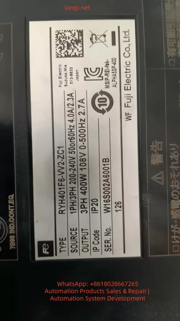
The Fuji ALPHA5 servo drive (models such as RYH401F6-VV2/ZC1) is an intelligent amplifier integrating high-resolution encoder feedback, auto-tuning, and vibration suppression functions. Its core components include:
- Power Input: Supports three-phase 200-240V AC. The label indicates “SOURCE 3PH 200-240V 50/60Hz 4.0A/2.7A”. Ensure voltage stability to avoid Hu (High Voltage) or Lu (Low Voltage) alarms.
- Motor Output: Connects U, V, W phases to the servo motor, supporting GY series motors with a maximum speed of 6000 r/min.
- Encoder Interface (CN2): Supports incremental (INC) or absolute (ABS) encoders with a resolution of 17-20 bits. The encoder provides position feedback; if there is no response, it triggers Et1/Et2 alarms.
- Sequence I/O (CN1): Processes signals such as S-ON (Servo On), FWD/REV (Forward/Reverse), +OT/-OT (Positive/Negative Overtravel), and RST (Alarm Reset).
- Communication Interface (CN3): RS-485 for PC Loader software connection, supporting parameter editing and monitoring.
- Analog Monitor (CN4): Outputs signals like speed and torque for easy debugging.
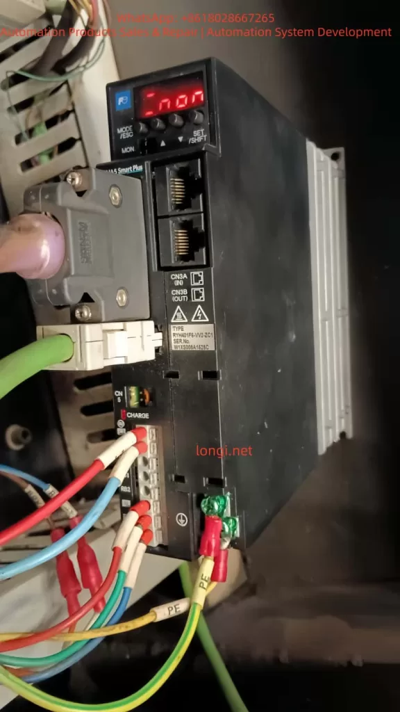
- Keypad Display: 7-segment LED displays status such as “rdy” (Ready), “n.on” (Not Enabled), or AL.xx alarm codes.
When replacing a drive, the new device does not automatically inherit old parameters because parameters are stored in EEPROM. The default settings assume a standard load and control mode (e.g., position control PA1_01=0), but in actual applications, they need to match the CNC’s pulse commands (PPI, CA/CB) and limit switches. Ignoring this step will cause the servo to fail to enable, displaying “n.on”, which is a system safety mechanism to prevent accidental movement.
The servo control principle is based on a closed-loop feedback: the CNC sends pulse commands, the drive converts them to motor rotation via the electronic gear ratio (PA1_06/PA1_07), and the encoder feeds back the actual position. If feedback is interrupted, the system detects a deviation overflow (PA2_69), triggering an overtravel alarm. Understanding these basics helps in locating problems.
Common Fault Analysis
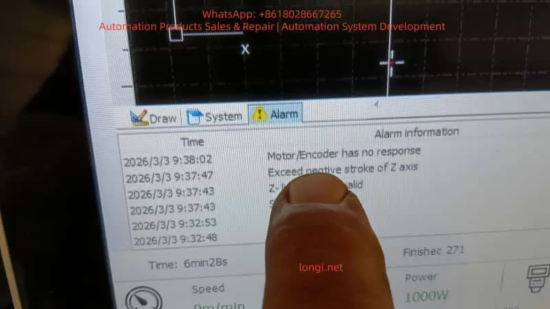
After replacing an ALPHA5 drive, the most common fault is a chain reaction caused by parameter mismatch. Below is an analysis of a typical user scenario: A customer in Brazil replaced a new drive and encountered “n.on” status, Z-axis negative stroke over-limit, encoder no-response, and servo alarms.
1. Cause of “n.on” Status
“n.on” means the servo is not enabled, usually due to a missing S-ON signal or an uncleared alarm. After replacement, the default parameters might disable S-ON (PA3_01=1), or the input signal assignment does not match the CN1 pinout. The new drive will also remain disabled to protect the motor if it detects an incompatible encoder.
2. Exceeded Negative Stroke of Z Axis
This is an Overtravel (OT) alarm triggered by a hardware limit switch (-OT) or when the software limit (PA2_26/PA2_27) exceeds the defined range. After replacing the drive, the default software limits are ±2e9 pulses, but if the zero point (homing) is not calibrated, position drift can cause a false over-limit. Mechanical factors like a jammed Z-axis can also amplify the issue.
3. Motor/Encoder Has No Response
Encoder failure is the primary suspect. Et1 indicates a single-rotation position detection failure, while Et2 indicates a memory data read error. When replacing the drive, if PA2_99 (Encoder Selection, default 0=Auto) is not set correctly, or if the cable is loose, the system cannot read the feedback, causing a CNC alarm. Noise interference or a 5V power interruption can also trigger this.
4. Z-Limit Invalid
The limit switch status is inconsistent, often caused by wiring errors or parameter PA2_25 (Software OT Enable, default 0=Disabled) not being configured. If the CNC relies on hard limits but the drive parameters ignore them, the alarm activates.
These faults are interconnected: encoder no-response leads to loss of position, which triggers OT; OT prevents S-ON, making “n.on” persistent. The root cause is mostly un-transferred parameters, with a probability of over 70%.
Detailed Parameter Configuration
Parameter configuration is the key to solving replacement issues. ALPHA5 parameters are divided into PA1 (Basic), PA2 (Application), and PA3 (Extended). Edit them using the keypad (MODE/SET keys) or PC Loader software. PC Loader supports batch transfer and is recommended for priority use.
1. Preparation
- Download PC Loader (from Fuji official website, version 3.2+).
- Connect RS-485 to CN3, set PA2_72 (Station No. = 1), PA2_73 (Baud Rate = 0 = 38400bps), PA2_97 (Protocol = 0).
- If you have an old drive parameter backup (Reload function), directly “Send all” to the new device.
- If no backup exists, initialize with Fn06 (init), then customize.
2. Motor and Encoder Matching Parameters
Ensure the drive recognizes the motor:
- PA2_98: Motor Type (0-15, according to GY motor label, e.g., 1=GYS series).
- PA2_99: Encoder Selection (0=Auto 17-20 bit, 1=17 bit). If there is no response, try setting it to 1.
- PA1_02: INC/ABS System (0=Incremental, 1=Absolute). For ABS, check the battery (CN5, lifespan 3 years, dL1 alarm indicates low voltage).
Example: For a GYS motor, set PA2_98=1, PA2_99=0. Save and power cycle.
3. Control Mode and Pulse Settings
Match the CNC command format:
- PA1_01: Control Mode (0=Position, applicable to CNC Z-axis).
- PA1_03: Pulse Input Form (0=Pulse + Direction positive logic, 1=Orthogonal A/B phase).
- Note: Must be consistent with CNC side parameters, otherwise the motor may run away or not turn.
- PA1_05: Pulses/Rev (0=Electronic gear mode).
- PA1_06 / PA1_07: Electronic Gear Numerator/Denominator (Default 16/1, adjust to machine units, e.g., 1mm = 10000 pulses).
- PA1_08: Output Pulses/Rev (2048, range 16-262144, ensure feedback matches).
If the Z-axis movement is inaccurate, calculate the ratio:
Gear Ratio=Encoder ResolutionCNC Pulse Resolution×Mechanical Reduction Ratio
4. Travel Limit and Homing Parameters
Addressing over-limit alarms:
- PA2_25: Software OT Enable (1=Enable).
- PA2_26 / PA2_27: Positive/Negative Limit Positions (-2e9 to 2e9 pulses, set according to Z-axis stroke, e.g., negative limit -1000000).
- PA2_28 / PA2_29: Detection Method (0=Stop immediately, 1=Decelerate to stop).
- PA2_06 – 18: Homing Parameters (PA2_06=Speed 500r/min, PA2_07=Direction, PA2_08=Offset).
- Execute Homing: Via ORG signal (reference value 5) or Fn02 preset position.
If limits are invalid, check sequence input assignment PA3_07/PA3_08 (+OT/-OT = 7/8).
5. Gain and Tuning Parameters
Optimize response to avoid vibration:
- PA1_13: Tuning Mode (10=Auto).
- PA1_14: Load Inertia Ratio (1.0, adjust according to actual load, e.g., set to 2.0 for machine tool Z-axis).
- PA1_54: Position Response Time Constant (Default 0ms, increase to smooth commands).
- PA1_55 – 57: Disturbance Response (Default 0, enhance anti-interference).
- PA1_70 – 76: Notch Filter (Suppress resonance frequency, e.g., PA1_70=1 Enable, PA1_71=1000Hz).
- PA1_77 – 86: Vibration Suppression (PA1_77=1 Enable, for low-frequency vibration).
Auto-tuning: Run with no load PA1_13=10, the system calculates gains.
6. Other Key Parameters
- PA1_25/26: Max Speed (6000r/min, Z-axis safe value 3000).
- PA1_27/28: Torque Limit (Default 300%, prevent overload).
- PA1_30: Zero Speed Range (50r/min).
- PA1_31: Deviation Unit (0=Pulses).
- PA1_32: Zero Deviation/In-Position Range (10 pulses).
- PA2_69: Deviation Overflow (15 revolutions, increase to avoid false alarms).
- PA1_36 – 40: Accel/Decel Time (Default 0ms, set 100ms to smooth Z-axis).
Write parameters to EEPROM (SET key), some require power restart (marked “Power”).
Troubleshooting and Debugging Steps
Systematic troubleshooting ensures efficient repair. Safety First: Power off for operation, use PPE.
1. Preliminary Diagnosis
- Power Cycle: Turn off for 5-10 minutes, restart to observe “n.on” or AL.xx.
- Check Display: If AL.xx flashes, refer to the manual (e.g., Et = Encoder fault).
- Monitor Mode: Press MODE to view on01 (Speed), on15 (DC link voltage).
2. Hardware Inspection
- Cables: Encoder CN2, Power CNB, I/O CN1. Use shielded cables to prevent noise, add ferrite cores.
- Limit Switches: Use a multimeter to test -OT/+OT continuity, simulate triggering.
- Power Supply: Measure 200-240V AC, P-N DC bus ~300VDC, Encoder 5V.
- Motor Rotation: Turn shaft manually with power off, check position change in CNC diagnostic mode.
3. Parameter Debugging
- Connect with PC Loader, read the log (dL1-3 = Battery/Data issues).
- Test Enable: Confirm S-ON (PA3_01=1), monitor input signals.
- Jog Test: Fn06 simulates Z-axis movement, check feedback.
- Swap Test: If multi-axis, swap encoder cables to isolate the problem.
4. Alarm Reset
- RST signal or Fn05 Reset.
- If persistent, check the root cause such as oL (Overload = Torque limit exceeded).
5. Advanced Debugging
- Fine-tune gains after auto-tuning.
- Vibration Suppression: Enable PA1_77, set frequency.
- Absolute System: Check battery, perform homing.
If unresolved, contact Fuji support with model and serial number.
Case Study: Repairing Z-Axis Fault for a Brazilian Customer
Scenario: CNC machine tool Z-axis alarms after replacing RYH401F6-VV2 drive.
Steps:
- Backup: Backup old parameters if possible, transfer to new.
- Encoder Match: Set PA2_99=1 to match encoder, solving “no response”.
- Limit Adjust: Adjust PA2_27=-500000 pulse limit to clear over-limit.
- Homing: Execute homing (ORG signal), verify in-position.
- Auto-Tune: PA1_13=10 to optimize.
Result: System restored, “rdy” displayed, Z-axis running precisely.
Best Practices and Maintenance
- Prevention: Backup parameters regularly, keep the environment clean and dust-free.
- Maintenance Cycle: Replace battery every 3 years, check fan life (warning output).
- Software Tools: Use PC Loader to monitor cumulative run time and alarm history.
- Noise Countermeasures: Separate power/signal cables, ground PE.
- Upgrade Considerations: If migrating from old series (e.g., FALDIC-α to ALPHA5), note alarm differences.
- Safety Standards: Comply with IEC standards, avoid use in life-related equipment.
Regular diagnostics, such as checking cumulative power time, help predict failures.
Conclusion
After replacing a Fuji ALPHA5 servo drive, systematic parameter configuration and troubleshooting can quickly restore CNC system performance. This article details technical details from basic to advanced levels, emphasizing the importance of parameter matching. Practice proves that 80% of issues stem from configuration; correct adjustment improves precision and reliability. For complex issues, refer to the official manual or professional services.