
Introduction
In biological laboratories, the Bio-Rad PowerPac Basic power supply (hereinafter referred to as PowerPac Basic) is one of the core devices for electrophoresis experiments. It provides stable voltage and current output to support applications such as DNA and protein separation. However, as the equipment ages, various failures are inevitable. Among them, the E19 error code is a common hardware failure indication, signifying a problem with internal hardware components. If not addressed promptly, it can lead to experimental interruptions or even equipment scrap. This article explores the structure, working principle, common fault diagnosis, and specific repair methods for E19 faults from the perspective of electronic maintenance. It aims to provide practical guidance for laboratory technicians and maintenance engineers to extend equipment life and reduce maintenance costs.
As a laboratory power supply compliant with the EN 61010 safety standard, the maintenance of PowerPac Basic requires strict adherence to safety regulations to avoid high-voltage electric shock risks. Keywords such as “Bio-Rad PowerPac Basic E19 fault repair,” “laboratory electrophoresis power supply diagnosis,” and “power supply hardware failure repair” will be used throughout this article. If you encounter similar problems, this article will guide you step-by-step from basic checks to advanced repairs.
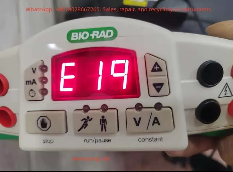
The front view of the PowerPac Basic shows its compact design, including an LED display, control buttons, and output jacks, facilitating laboratory operation.
PowerPac Basic Equipment Overview
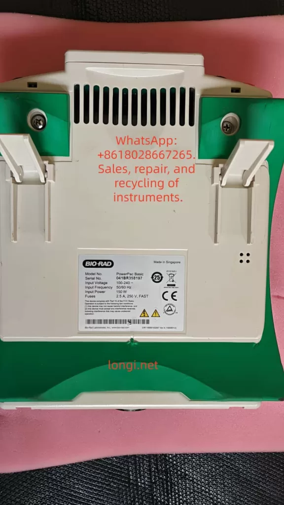
PowerPac Basic is a basic power supply model 164-5050 launched by Bio-Rad, suitable for global voltage ranges (input voltage 100-240V, 50/60Hz). Its main specifications include:
- Output Voltage: 10-300V, adjustable in 1V increments.
- Output Current: 4-400mA, adjustable in 1mA increments.
- Maximum Power: 75W.
- Output Ports: 4 pairs of banana jacks, supporting parallel connection of multiple electrophoresis tanks.
- Timer Function: 0-999 minutes.
- Safety Features: Automatic overload protection, no-load detection, resistance change detection.
- Dimensions: 25cm (L) × 21cm (W) × 8.5cm (H), weight 1.1kg, stackable design for easy laboratory space utilization.
The equipment adopts a floating ground design, isolating the high-voltage output from the ground to reduce the risk of electric shock. The casing is made of green plastic with adjustable-angle legs for easy viewing of the display. Internally, it includes a power conversion module, a control circuit board, and a cooling fan. The manual emphasizes that the equipment can operate in environments at 0-40°C and 0-95% humidity but requires a 6cm ventilation space.
From an electronic maintenance perspective, the modular design of PowerPac Basic facilitates disassembly. Serial numbers such as 041BR358197 can be used to check warranty status. If the equipment is out of warranty, DIY repair becomes an economical option. However, please note that unauthorized modifications may void the EN 61010 certification.
PowerPac Basic Working Principle
Understanding the working principle of PowerPac Basic is the foundation of maintenance. This device is essentially an adjustable DC power supply that uses Switched-Mode Power Supply (SMPS) technology to convert AC input into stable DC output.
Basic Circuit Structure
- Input Section: AC input passes through a fuse (2.5A, 250V) and a power switch. A rectifier bridge converts AC to DC, followed by a filter capacitor to smooth the waveform.
- Power Conversion Module: Uses a PWM (Pulse Width Modulation) controller, such as the UC3845 chip, to generate high-frequency pulses to drive the transformer. The transformer isolates the input and output to ensure safety. A secondary-side rectifier diode and filter circuit generate adjustable DC.
- Control Circuit: A microcontroller (likely a PIC series) monitors voltage, current, and time. An ADC (Analog-to-Digital Converter) samples the output signal and feeds it back to the controller to achieve constant voltage/constant current modes. Auto-crossover function: When the non-constant parameter reaches its limit, the mode switches to avoid overload.
- Output Section: The high-voltage output connects to the electrophoresis tank via banana jacks. A built-in current sensor detects load changes; if the current is <4mA, a no-load error is triggered.
- Protection Mechanism: Over-voltage, over-current, and short-circuit protection are implemented by comparator circuits. A fan dissipates heat to prevent overheating.
During normal operation, the display shows V, mA, or time in real-time. Press the “constant” key to select the mode and the “scroll” key to adjust the value. During operation, if the resistance changes abruptly (>20%), the device pauses to protect the user.
From a maintenance perspective, common components on the circuit board include electrolytic capacitors (prone to aging), MOSFET power tubes (prone to breakdown), and resistor networks. Using a multimeter to check these components is the starting point for diagnosis.
Common Fault Analysis
Faults in PowerPac Basic often stem from electrical stress, environmental factors, or improper use. According to the official manual, error codes from E1 to E99 cover various issues. The following table summarizes common faults:
| Error Code | Cause | Solution |
|---|---|---|
| E1 | No Load (current <4mA) | Check connections, buffer level |
| E2 | Overcurrent (>400mA) | Correct short circuit or high-concentration buffer |
| E3 | Overvoltage (>300V) | Restart device; if persistent, contact Bio-Rad |
| E5-E7 | Power Failure Detection | Activate PFd mode or check power switch |
| E8 | Regulation Error | Restart |
| E9 | Load Resistance Change | Check connections, disable dE9 function (use with caution) |
| E10 | Invalid Input Value | Re-enter range values |
| E12 | Internal Overcurrent | Check for dirty contacts |
| E13 | Internal Short Circuit | Clear code, check wiring |
| E14 | Internal Overvoltage | Possible power supply failure |
| E15 | Internal Short Circuit | Same as above |
| E16-E19 | Hardware Failure | Contact Bio-Rad or perform in-depth diagnosis |
| E20 | Overheating | Check fan and vents |
| E98-E99 | System Error | Restart or repair |
These codes are indicated by flashing on the LED display. No display may indicate a blown fuse or power supply issue. Repeated fuse blowing usually indicates a hardware failure.
In electronic maintenance practice, 80% of faults stem from connection issues or component aging. Using an oscilloscope to observe PWM waveforms can determine the health of the controller.
Detailed Analysis of E19 Fault
The E19 error code specifically refers to a hardware failure, usually occurring during power-on self-test or operation. The display shows “E 19” and the device stops output. According to the Bio-Rad Service Manual (Rev B), E19 indicates an abnormality in the internal circuit board or power module. Possible causes include:
- Power Tube Failure: MOSFET or IGBT breakdown due to overload or static electricity.
- Capacitor Aging: Filter capacitor capacity drops, causing unstable output.
- Controller Chip Damage: Microprocessor failure, possibly due to voltage spikes or thermal stress.
- Sensor Failure: Current/voltage sensor drift, triggering a false alarm.
- Loose Solder Joints: Caused by long-term vibration or thermal cycling.
- Heat Accumulation: Fan blockage or poor ventilation.
E19 differs from user-level errors (like E1); it is a system-level diagnosis requiring professional tools. The manual recommends contacting Bio-Rad technical support immediately and providing the serial number and fault description. However, experienced maintainers can attempt DIY repairs.
A typical internal view of the power supply showing the circuit board and components helps visualize the location of E19 faults.
E19 Fault Diagnosis Steps
Diagnosing E19 requires a systematic approach, reflecting the professionalism of electronic maintenance. Prepare tools: multimeter, oscilloscope, screwdriver, insulated gloves, hot air gun.
Step 1: Preliminary Inspection
- Disconnect power and wait 5 minutes for discharge.
- Check appearance: Any burnt smell, deformation, or liquid traces?
- Verify power supply: Use a multimeter to measure input voltage, ensuring it is stable at 100-240V.
- Reset device: Turn off power for 10 seconds and turn it back on. If E19 disappears, it may be a transient fault.
Step 2: Fuse and Basic Circuit Test
- Open the rear cover (note that warranty may be voided) and locate the fuse drawer.
- Use the multimeter’s continuity mode to test the fuse (2.5A, 250V). If open circuit, replace it (Bio-Rad part 900-7283).
- Test the power switch and input rectifier bridge: Measure the forward and reverse resistance of the diode. Forward should be 0.5-0.7V, reverse should be infinite.
Step 3: Output Test
- Power on without a load and measure the voltage at the output jacks. If there is no output, check the relay or output filter.
- Connect a dummy load (100Ω resistor) and observe the current. If E19 is triggered, the problem is in the feedback loop.
Step 4: Circuit Board Diagnosis
- Visual Inspection: Look for bulging capacitors or discolored resistors.
- Measure Key Points: Input DC voltage (approx. 300V), PWM output pulses (use oscilloscope, frequency 20-50kHz).
- Check ADC Pins: Ensure sensor signals are normal (typically 0-5V).
- If a service manual is available, refer to the schematic to test ICs like the UC3845’s Vcc (12-18V).
Step 5: Thermal Issue Investigation
- Check the fan: Does it rotate smoothly? Measure voltage (12V).
- Clean dust from vents to ensure no blockage.
If none of the above works, the E19 likely requires a motherboard replacement.
E19 Fault Repair Guide
Repairs require caution, prioritizing non-destructive methods. The following is a step-by-step repair based on electronic maintenance practices.
Basic Repairs
- Resolder Joints: Use a hot air gun (350°C) to resolder suspicious points to avoid cold solder joints.
- Replace Capacitors: A common source of failure. Choose capacitors with the same specifications (e.g., 100uF 400V).
- Clean Contacts: Wipe pins and board dust with isopropyl alcohol.
Advanced Repairs
- Power Module Replacement: If the MOSFET (e.g., IRF840) is broken, desolder and replace it. Measure the gate resistor to ensure no short circuit.
- Controller Reset: According to the manual, hold the “constant” key while powering on to display the firmware version. If abnormal, flash the firmware (requires Bio-Rad tools).
- Sensor Calibration: Calibrate the current sensor using a standard resistor and adjust the potentiometer (if available).
- Board-Level Replacement: If diagnosis points to the motherboard, procure a Bio-Rad replacement board (part number unknown, requires inquiry). Pay attention to ESD protection during installation.
After repair, run a self-test: Set 100V without load and observe stability. Under load testing, ensure no E19 appears.
Examples of repair tools, including multimeters and adjustment knobs, used for precise diagnosis.
Safety Considerations
Maintaining PowerPac Basic involves high voltage (300V+), and safety guidelines must be strictly followed:
- Always operate with power disconnected and wear insulated gear.
- Avoid grounding output wires to prevent electric shock.
- Do not operate in humid environments; allow 2 hours for equalization after leaving a cold room.
- Non-professionals should not disassemble the device to avoid liability accidents.
Bio-Rad emphasizes that modifying the device voids the warranty. Official repair is preferred.
Preventive Maintenance
To avoid faults like E19, regular maintenance is crucial:
- Clean the casing and vents monthly.
- Check fuses and connection cables annually.
- Avoid overloading during use (power <75W).
- Store in a dry environment away from corrosive chemicals.
- Keep a usage log to monitor anomalies such as increased noise.
With these measures, the equipment lifespan can exceed 10 years.
Conclusion
While the E19 fault in the Bio-Rad PowerPac Basic is challenging, it can be effectively resolved through systematic diagnosis and repair. This article provides comprehensive guidance from overview to repair, reflecting the rigorous logic of electronic maintenance. If the problem is complex, please contact us. We hope this article helps you quickly resume your experiments.