
Introduction
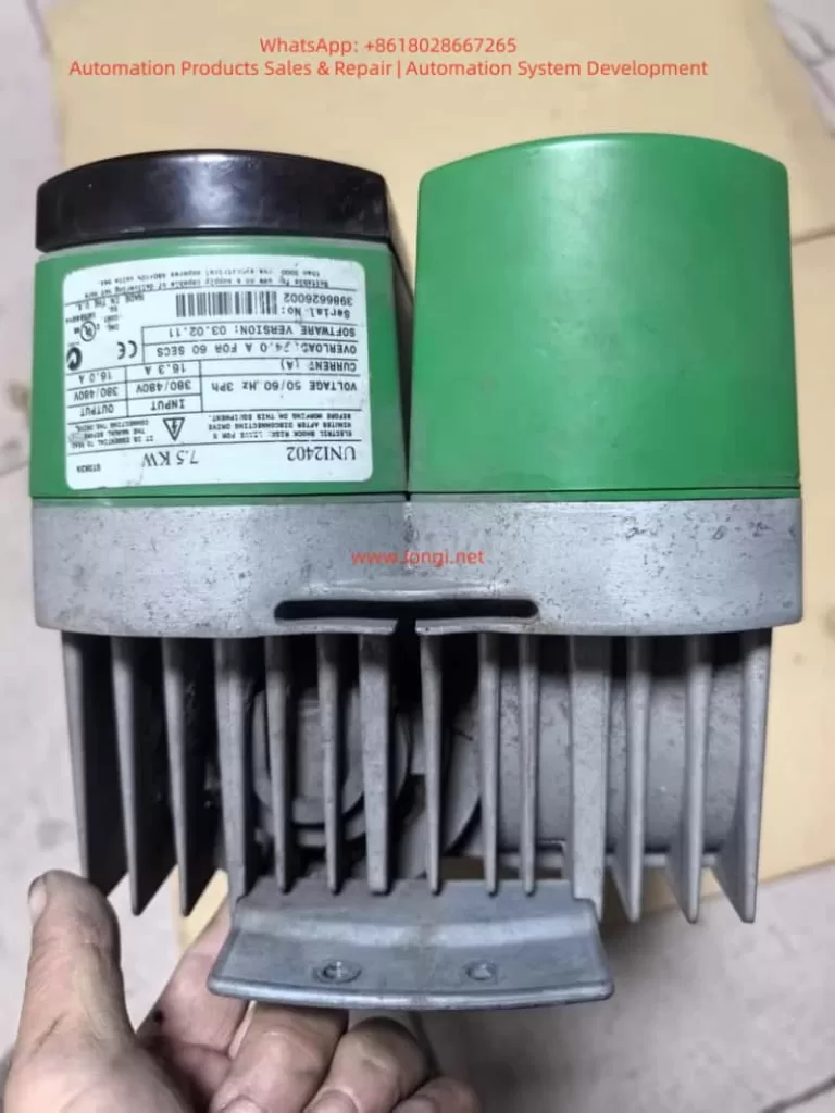
The Control Techniques (now part of Nidec Group) UNIDRIVE V3 series drives, including the UNI2402 model, are widely used in industrial automation as versatile variable frequency drives (VFDs) supporting V/F control, closed-loop vector control, and servo control modes. Based on the AUG_v3 – Unidri.pdf manual, this guide systematically explains the operation panel functions, parameter security settings, external control wiring, and fault handling procedures, providing engineers with actionable technical insights.
Chapter 1: Operation Panel Functions and Parameter Security Settings
1.1 Operation Panel Components and Functions
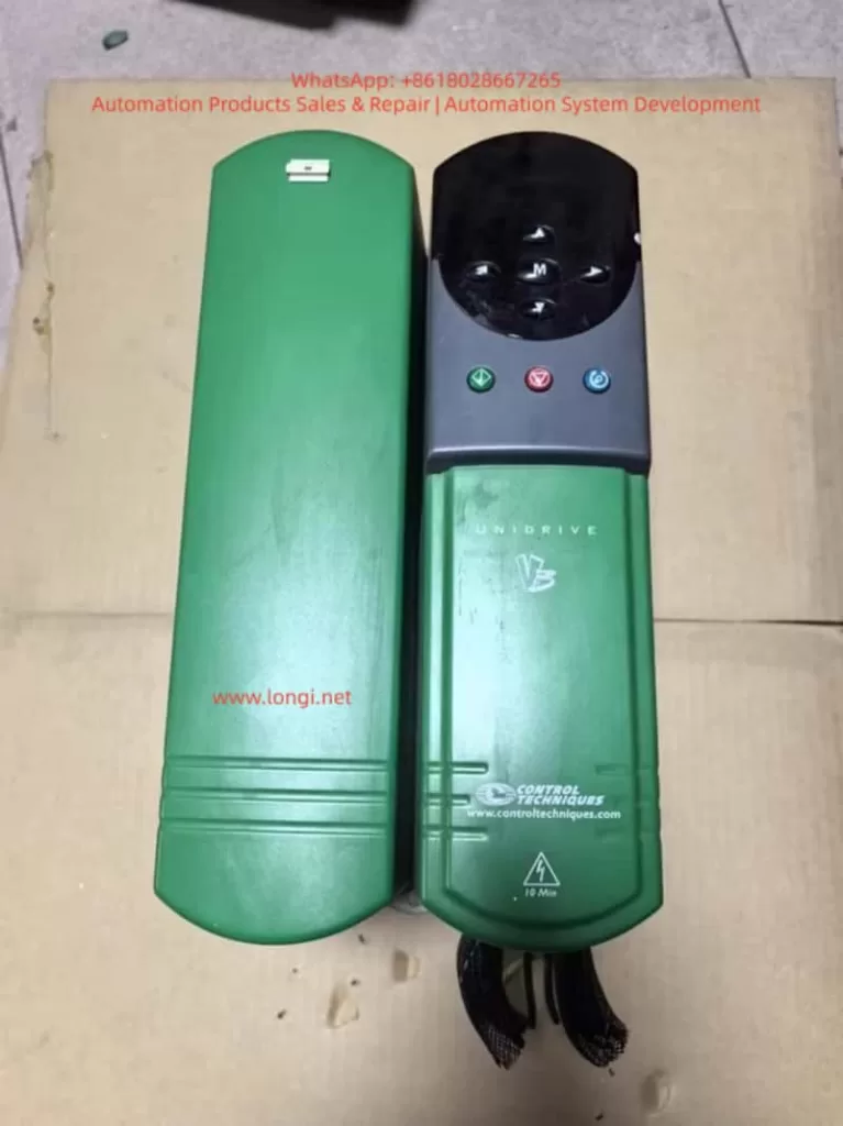
The UNIDRIVE V3 operation panel features a two-line LED display + 8 function keys, supporting parameter viewing, modification, and drive control (Figure 1).
| Key | Function Description |
|---|---|
| Up/Down | Increment/decrement parameter values or scroll menus |
| Left/Right | Switch parameter digits or enter submenus |
| Mode | Toggle display modes (status/parameter/edit) |
| Start | Start the drive (requires permissions) |
| Stop/Reset | Stop the drive or reset faults |
| Reverse | Reverse operation (requires permissions) |
| F1-F6 | User-defined function keys (assigned via parameters) |
Core Functions:
- Status Mode: Displays parameter values or status strings (e.g., frequency, current).
- Parameter Mode: View or modify parameters (e.g., Pr 0.00 = Operation Mode, Pr 1.04 = Reference Source Selection).
- Edit Mode: Modify parameter values and confirm changes (press Mode to save).
1.2 Password Setup and Access Restrictions
The UNIDRIVE V3 supports two-level password protection (Table 1) to prevent unauthorized operations or parameter tampering.
| Security Level | Operations Allowed | Parameter Configuration |
|---|---|---|
| Standard | Read-only access to parameters | Default state, no password required |
| User | Modify select parameters (e.g., frequency setpoint) | Set Pr 0.34 = 1–255 (password), Pr 0.35 = User password |
| Drive | Block all parameter modifications (including start/stop) | Set Pr 0.34 = 0 (disable User Security), Pr xx.00 = 2000 (disable Standard Security) |
Steps:
- Set User Password:
- Navigate to Parameter Mode, locate Pr 0.34 (User Security Enable).
- Enter a password value (e.g., 1234) and press Mode to save.
- Configure Pr 0.35 = User password (must match Pr 0.34).
- Remove Password:
- Set Pr 0.34 to 0 or reset via Pr 0.35 with the correct password.
- Execute Drive Reset (Pr 0.00 = 1000, press Stop/Reset).
- Restore Factory Defaults:
- Set Pr 0.00 = 1000 and press Stop/Reset.
- Alternatively, access “Trip Log” in the menu and select “Factory Reset”.
Chapter 2: External Terminal Control and Speed Regulation
2.1 Forward/Reverse Control via Digital Inputs
The UNIDRIVE V3 supports forward/reverse operation through digital input terminals (F1–F6).
Wiring:
- Connect F1 to a PLC output (e.g., 24V DC) for forward rotation.
- Connect F2 to another PLC output for reverse rotation.
- Ensure COM (common terminal) is tied to 0V DC.
Parameter Configuration:
- Assign functions to terminals:
- Pr 8.10 (F1 Destination) = 1 (Forward Enable).
- Pr 8.13 (F2 Destination) = 2 (Reverse Enable).
- Set operation mode to External Terminal Control:
- Pr 0.00 = 4 (Open Loop) or 5 (Closed Loop Vector).
- Configure safety parameters:
- Pr 6.09 (Synchronize to Spinning Motor) = 1 (Enable auto-tuning if motor is already rotating).
2.2 Analog Frequency Regulation via Potentiometer
To adjust speed using an external potentiometer, wire the Analog Input 1 (AI1) terminal.
Wiring:
- Connect the potentiometer wiper to AI1.
- Tie AI1+ to +10V DC (provided by the drive) and AI1– to 0V DC.
Parameter Configuration:
- Set reference source to Analog Input 1:
- Pr 1.04 = 1 (AI1 as frequency reference).
- Calibrate analog input:
- Pr 7.07 (AI1 Offset Trim) = 0% (eliminate zero offset).
- Pr 7.08 (AI1 Scaling) = 100% (full scale = 50Hz).
- Configure ramp rates:
- Pr 2.01 (Post-Ramp Reference) = 50Hz (target frequency).
- Pr 2.11 (Acceleration Rate) = 10s (0–50Hz acceleration time).
- Pr 2.12 (Deceleration Rate) = 10s (50–0Hz deceleration time).
Chapter 3: Fault Diagnosis and Resolution
The UNIDRIVE V3 logs fault codes and timestamps in the Trip Log, accessible via the operation panel or serial tools (Figure 3).
3.1 Common Fault Codes and Causes
| Fault Code | Description | Possible Causes |
|---|---|---|
| OV | DC Bus Overvoltage | Short deceleration time, missing brake resistor, grid voltage fluctuations |
| LU | DC Bus Undervoltage | Low grid voltage, blown fuse, rectifier module failure |
| OH | Heatsink Overtemperature | Poor ventilation, sustained overload, high ambient temperature |
| OC | Output Overcurrent | Motor short circuit, short acceleration time, low current limit (Pr 4.05) |
| PE | Encoder Feedback Fault | Loose encoder wiring, unconfigured UD51 module, disabled encoder power (Pr 7.25) |
| CF | Communication Fault | Mismatched RS485 baud rate (Pr 11.25), missing termination resistor, address conflict |
3.2 Fault Resolution Workflow
- Access Trip Log:
- Navigate to Menu 10 (Status Flags/Trip Log) to view the last 10 fault records (code, time).
- Record operational context (e.g., frequency, load) during the fault.
- Troubleshoot:
- OV Fault: Extend deceleration time (Pr 2.12), check brake resistor (Pr 5.18 = Brake Unit Enable).
- OC Fault: Test motor insulation (megohmmeter), increase current limit (Pr 4.05 = 150% rated current).
- PE Fault: Reconnect encoder (A/B/Z phases), configure UD51 parameters (Pr 16.01 = Module Type).
- Reset and Test:
- Clear Trip Log (Pr 10.36 = 1).
- Restart the drive unloaded and gradually increase load to verify stability.
Chapter 4: Advanced Features and Optimization
4.1 Multi-Speed Operation
Enable 8-speed control via digital input combinations (requires UD70 Large Option Module):
- Assign terminal functions (e.g., F1 = Speed 1, F2 = Speed 2).
- Set frequencies for each speed (Pr 9.01–Pr 9.08).
- Configure logic combinations (Pr 9.10–Pr 9.15).
4.2 Energy-Efficient Operation
Activate High-Efficiency Space Vector Modulation (Pr 5.19 = 1) to reduce switching losses for fan/pump loads:
- Path: Menu 5 (Machine Control) → Pr 5.19.
- Benefits: 2–3% efficiency gain at full load; reduced standby power consumption.
4.3 Communication Protocol Expansion
The UNIDRIVE V3 supports Modbus RTU, CANopen, Profibus-DP. Configure:
- Serial parameters (Pr 11.24 = Protocol Type, Pr 11.25 = Baud Rate).
- Node address (Pr 11.23 = 1–247).
- Map registers (e.g., Pr 0.00 = Status Word, Pr 1.04 = Frequency Setpoint).
Conclusion
This guide systematically explains the UNIDRIVE V3 (UNI2402) drive’s operation panel functions, parameter security, external control wiring, and fault handling, referencing key manual sections (e.g., Menu 0/6/10/13). Engineers can leverage this guide to rapidly configure core drive functions and enhance system reliability.