
I. Introduction
In the field of industrial automation, servo systems are core components for achieving precise motion control, and their stability directly impacts production efficiency and product quality. The Berger Lahr EXC-30 series servo drives are widely used in applications such as machine tools, packaging machinery, and robots due to their high precision and reliability. However, during long-term operation, the ER-13 overload fault is one of the most common alarms. If not addressed promptly, this fault can lead to motor burnout, drive damage, and even production shutdowns. Based on the hardware characteristics and control logic of the EXC-30 series, this article provides an in-depth analysis of the causes, troubleshooting procedures, and solutions for the ER-13 fault, offering practical guidance for engineering technicians.
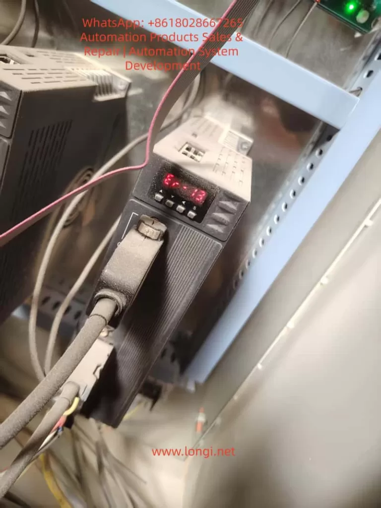
II. Definition and Classification of the ER-13 Fault Code
According to the Berger Lahr EXC-30 series user manual, the ER-13 fault corresponds to an “Overload” condition and is triggered in two scenarios:
- During power-on of the control supply: The drive detects abnormal current at the moment of power-up, usually related to hardware failures.
- During motor operation: The actual torque of the motor exceeds its rated torque (or the torque limit set by the drive), or excessive torque fluctuations occur due to control abnormalities.
The core logic of this fault is as follows: The drive continuously monitors the motor winding current through current sensors. When the current exceeds 1.5 times the rated value (or the set overload threshold) and persists for a certain duration (typically 1-3 seconds), the ER-13 alarm is triggered, and the drive output is cut off to protect the motor and the drive itself.
III. In-depth Analysis of the Causes of the ER-13 Fault
The causes of the ER-13 fault are complex and require a comprehensive assessment based on hardware status, load characteristics, and parameter settings. The following is a detailed classification analysis:
(I) ER-13 Triggered at Power-on: Primarily Hardware Failures
1. Circuit Board Failures
- Current Sensor Drift: In the EXC-30 series drives, failures in the current detection circuit (e.g., Hall sensors), drive circuit (e.g., IGBT modules), or control board (e.g., CPU board) can lead to abnormal current detection at power-up. For example:
- If the current sensor drifts, the detected current value may be significantly higher than the actual value, triggering overload protection.
- If the IGBT module is short-circuited, a short circuit occurs at the power output terminal, causing a sudden increase in current at power-up.
- If the control board program malfunctions, it may misinterpret current signals, resulting in false alarms.
2. Motor Winding Short Circuit
A short circuit between phases or to ground in the motor stator windings can cause a rapid increase in current at power-up, exceeding the drive’s overload threshold. This is often accompanied by motor overheating and a burning smell.
3. Brake Not Released (for motors with brakes)
For certain EXC-30 series models equipped with electromagnetic brakes (e.g., motors with brakes), if the brake coil is not energized or the brake is mechanically jammed, the motor is braked at power-up. The drive detects a “locked-rotor current” and triggers the ER-13 fault.
(II) ER-13 Triggered During Operation: Primarily Load and Control Issues
1. Operation Beyond Rated Torque
This is the most common cause and includes the following scenarios:
- Excessive Load: Mechanical transmission system issues such as insufficient lubrication on guide rails, worn screw nuts, or external impact loads (e.g., material jamming in packaging machinery) can increase the load beyond the motor’s rated capacity.
- Improper Parameter Settings: Incorrect settings for parameters such as the torque limit (e.g., P001 in EXC-30), start-stop frequency (P002), and acceleration/deceleration time (P004) can lead to operation beyond rated torque. For example:
- Setting the torque limit (P001) too high (exceeding the motor’s rated torque).
- Setting the start-stop frequency (P002) too fast, causing the starting impact torque to exceed the rated value.
- Setting the acceleration/deceleration time (P004) too short, resulting in excessive acceleration and a surge in torque.
2. Brake Not Released During Operation
For motors with brakes, if the brake coil loses power or experiences a mechanical failure (e.g., worn brake pads, failed springs) during operation, the brake may not fully release. The motor then has to overcome the braking torque, causing the actual torque to exceed the rated value.
3. Motor Instability and Oscillation
Improper adjustment of servo system gains (e.g., excessively high position gain P003 or speed gain P005) can cause the motor to oscillate during operation, with torque fluctuating periodically. If the peak torque exceeds the rated value, the ER-13 fault is triggered. This is common in scenarios with a high load inertia ratio (load inertia/motor inertia), such as robot arms or large worktables.
4. Wiring Errors
- Power Line Disconnection: If one of the three-phase power lines (UVW) to the motor is disconnected (e.g., due to loose connectors or crushed wires), the motor operates in a phase-loss condition, reducing torque. To maintain speed, the current increases, eventually leading to overload.
- Incorrect Encoder Wiring: If the encoder feedback lines (e.g., A/B phase, Z phase) are reversed or loose, the drive cannot accurately detect the motor’s position or speed, causing control algorithm disruptions and abnormal torque output.
IV. Systematic Troubleshooting Procedure for the ER-13 Fault
For the ER-13 fault in the EXC-30 series, follow the principle of “checking external factors before internal ones, mechanical issues before electrical ones, and parameters before hardware,” and proceed with the following steps:
Step 1: Visual and Wiring Inspection (Quickly Eliminate Obvious Faults)
- Check Wires and Connectors: Examine the power lines (UVW), encoder lines, and brake lines for breaks, oxidation, or looseness (e.g., bent connector pins).
- Check Mechanical Status: Manually rotate the motor shaft (after disconnecting the load) to check for any binding (e.g., sticky guide rails, bent screw rods). Check the load for foreign objects (e.g., material rolls in packaging machinery, iron filings in machine tools).
- Check the Brake: For motors with brakes, listen for a “click” sound at power-up (indicating brake release). Use a multimeter to measure the brake coil voltage (usually DC24V). If the voltage is normal but there is no release action, the brake has a mechanical failure.
Step 2: Load and Parameter Verification (Core Troubleshooting Step)
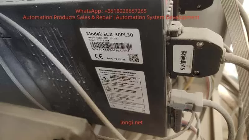
- Measure Load Torque: Use a torque wrench or torque sensor to measure the actual load torque and compare it with the motor’s rated torque (which can be found in the EXC-30 series model specifications, e.g., the rated torque of the ECX-30PL30 is 10 N·m).
- Verify Parameter Settings: Enter the drive’s parameter mode (set via the operation panel or software in the EXC-30 series) and check the following key parameters:
- Torque Limit (P001): Ensure it does not exceed the motor’s rated torque (recommended to be set at 1.2-1.5 times the rated value).
- Start-Stop Frequency (P002): Check if it is too high (e.g., exceeding 50% of the motor’s rated frequency).
- Acceleration/Deceleration Time (P004): Check if it is too short (e.g., start time < 0.1 seconds).
- Gain Parameters (P003 position gain, P005 speed gain): Check if they are too high (gradually reduce them using the “gain adjustment” function and observe for motor oscillation).
Step 3: Electrical Testing (Locate Wiring and Hardware Faults)
- Power Line Testing: Use a multimeter to measure the resistance between the three phases (UVW) of the motor. The resistance should be balanced (e.g., 0.5 Ω ± 10%). If one phase shows infinite resistance, there is a break. Measure the resistance between the power lines and ground (should be > 10 MΩ). A lower value indicates insulation damage.
- Encoder Line Testing: Use an oscilloscope to measure the encoder’s A/B phase signals (normal signals are differential pulses with a frequency proportional to the motor speed). If the signals are missing or distorted, the encoder wiring is incorrect or the encoder is damaged.
- Current Testing: Use a clamp-on ammeter to measure the motor’s operating current (should be less than the rated current). If the current exceeds 1.5 times the rated value, the load is too heavy or the parameters are improperly set.
- Brake Testing: Measure the brake coil resistance (normal values range from tens to hundreds of ohms). If the resistance is infinite, the coil is burned out. Measure the brake release time (should be < 0.5 seconds). A longer time indicates mechanical jamming.
Step 4: In-depth Hardware Testing (Circuit Boards and Drive)
If no fault is found in the previous steps, disassemble the drive for hardware testing:
- Current Sensor: Measure the sensor’s output voltage (should be proportional to the current, e.g., 2.5V for 10A). If the output is abnormal, the sensor is damaged.
- IGBT Module: Use a multimeter to measure the resistance between the collector (C) and emitter (E) of the IGBT (should be infinite). If it conducts, the module is short-circuited.
- Control Board: Check for swollen electrolytic capacitors or burned resistors on the board. Use a programmer to read the control board program (if corrupted, reprogram it).
V. Solutions and Case Studies for the ER-13 Fault
(I) Common Fault Solutions
| Fault Cause | Solution |
|---|---|
| Excessive Load | Clear mechanical foreign objects, lubricate guide rails, use a lighter load, or upgrade to a higher-power motor/drive. |
| Brake Not Released | Repair the brake coil (replace or rewind it), adjust the brake pad clearance, or check the brake power supply. |
| Improper Parameter Settings | Reduce the torque limit (P001), increase the acceleration/deceleration time (P004), or adjust the gains (P003/P005). |
| Power Line Disconnection | Reconnect the wires (crimp terminals) or replace damaged wires. |
| Incorrect Encoder Wiring | Verify the encoder pin definitions (usually a 25-pin D-type connector in EXC-30 series) and reconnect correctly. |
| Circuit Board Failure | Replace the current sensor, IGBT module, or control board (recommended to return to the manufacturer for repair). |
(II) Typical Case Studies
Case 1: ER-13 Due to Material Jamming in Packaging Machinery
- Fault Phenomenon: An EXC-30 servo motor (model ECX-30PL30) on a packaging machine suddenly reported ER-13 during operation and could not be restarted after shutdown.
- Troubleshooting Process:
- Manually rotating the motor shaft revealed that the load side (material roll) was jammed and could not rotate.
- Disassembling the packaging machine revealed that a piece of packaging paper was stuck on the material roll support, causing a sudden increase in load torque.
- After clearing the foreign object, the motor shaft rotated smoothly manually, and the drive restarted without fault.
- Solution: Add a protective cover to the material roll support and regularly clean foreign objects.
Case 2: ER-13 Due to Brake Coil Burnout
- Fault Phenomenon: An EXC-30 servo motor with a brake (model ECX-30BL30) on a machine tool frequently reported ER-13 during operation, and the brake did not release with a sound.
- Troubleshooting Process:
- Using a multimeter, the brake coil voltage was measured at DC24V (normal), but the coil resistance was infinite (normal value: 120 Ω).
- Disassembling the brake revealed that the coil winding was burned black (due to long-term overload).
- After replacing the brake coil, power-up testing showed normal brake release, and the motor operated without alarm.
- Solution: Check the brake load (ensure it does not exceed the rated braking torque) and avoid long-term overload.
Case 3: ER-13 Due to Improper Gain Adjustment
- Fault Phenomenon: An EXC-30 servo motor (model ECX-30HL30) on a robot arm oscillated during high-speed operation, accompanied by ER-13 alarms.
- Troubleshooting Process:
- Using an oscilloscope to measure the motor current revealed periodic fluctuations in the current waveform, with peak values exceeding the rated value.
- Checking the parameters revealed that the position gain (P003) was set to 1000 (rated value: 500), and the speed gain (P005) was set to 800 (rated value: 400).
- Gradually reducing the gains (P003 to 600, P005 to 500) eliminated the oscillation and prevented further ER-13 alarms.
- Solution: Based on the load inertia ratio (8:1 in this case), recalculate the gain parameters (recommended to reduce gains by 20%-30% when the inertia ratio exceeds 5:1).
VI. Preventive Measures for the ER-13 Fault
To reduce the occurrence of the ER-13 fault, take the following measures in terms of design, installation, and maintenance:
- Proper Component Selection: Select motors based on load torque and inertia (recommended load inertia ratio < 5:1) to avoid “overloading a small motor.”
- Parameter Optimization: Verify parameters (torque limit, start-stop frequency, gains) before power-up and adjust them according to load characteristics (e.g., increase acceleration/deceleration time for heavy loads).
- Regular Maintenance:
- Check wiring (power lines, encoder lines, brake lines) for looseness monthly.
- Lubricate mechanical transmission parts (guide rails, screw rods) and clean dust (to prevent it from entering the drive) quarterly.
- Test motor winding insulation annually (use a megohmmeter to measure ground resistance, which should be > 10 MΩ).
- Environmental Protection: Install the drive in a well-ventilated area (temperature < 40°C) and avoid humid or dusty environments (add protective covers if necessary for harsh environments).
VII. Conclusion
The ER-13 overload fault in the Berger Lahr EXC-30 series is the result of the interaction between hardware, load, and parameters. During troubleshooting, follow a logical approach from “external to internal” and “mechanical to electrical,” focusing on load status, parameter settings, and wiring integrity. Through the analysis and case studies in this article, engineering technicians can quickly locate the root cause of the fault and implement targeted solutions. Additionally, by selecting components properly, performing regular maintenance, and optimizing parameters, the occurrence of the ER-13 fault can be effectively prevented, ensuring the stable operation of the servo system.
In the field of industrial automation, the core of fault handling is “understanding system logic + mastering troubleshooting methods.” It is hoped that this article will provide practical technical references for Berger Lahr servo users and improve equipment maintenance efficiency.