
Introduction
In industrial automation systems, variable frequency drives (VFDs) are widely used for controlling motors in applications such as pumps, fans, compressors, conveyors, machine tools, and production equipment. As the operating environment becomes more demanding, VFDs are exposed to voltage fluctuations, temperature stress, dust contamination, and long-term electrical aging.
When a drive displays a fault code, many technicians immediately associate the alarm name with the failure location. For example, an overcurrent alarm is often considered an IGBT failure, while an undervoltage alarm is assumed to be caused by insufficient input voltage.
However, modern industrial VFDs use complex protection and monitoring systems. A fault code usually represents the condition detected by the control system, not necessarily the exact failed component.
A typical example is the Mitsubishi FR-F840-00620-2-60, a 400V-class high-power inverter with approximately 62A rated output current and 30kW motor capacity. In field repair work, this model may experience the E.UVT (Undervoltage Trip) alarm. Especially when the drive reports E.UVT immediately after power-on, the actual cause is often not simply an external power supply problem.
Possible causes include:
- Three-phase input abnormality;
- Rectifier circuit failure;
- DC bus charging problems;
- Pre-charge resistor or relay failure;
- DC bus voltage detection circuit malfunction;
- Control power instability;
- Main control board sampling errors.
This article provides a systematic troubleshooting method for Mitsubishi FR-F840 E.UVT faults, especially for cases where the inverter alarms immediately after energization and the power module has already been confirmed to be normal.
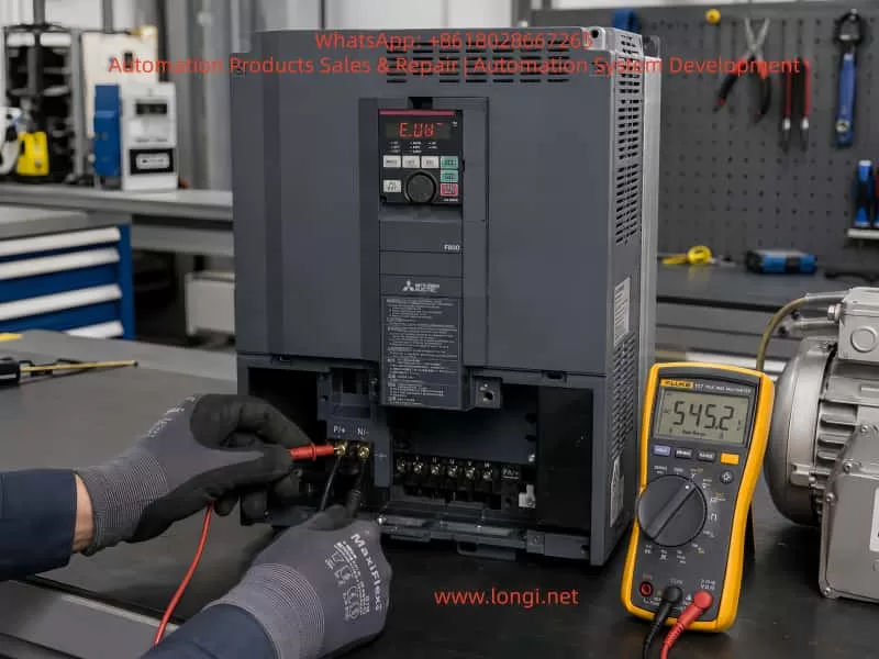
1. Basic Structure of Mitsubishi FR-F840-00620-2-60
Before troubleshooting an undervoltage fault, it is necessary to understand the internal power structure of the inverter.
The Mitsubishi FR-F840 belongs to the F800 series, designed mainly for industrial fan, pump, HVAC, and general-purpose drive applications.
The basic energy conversion process is:
Three-phase AC input

R / S / T

↓

Input protection and filtering

↓

Rectifier bridge

↓

DC bus

P(+) / N(-)

↓

DC capacitors

↓

IGBT inverter module

↓

U / V / W output

↓

Motor
The main functions of each section are:
Rectifier section
Converts three-phase AC voltage into DC voltage.
DC bus section
Stores energy and stabilizes the DC voltage.
IGBT inverter section
Converts DC voltage into variable-frequency AC output for motor control.
Control board
Responsible for:
- Voltage monitoring;
- Current detection;
- Protection logic;
- PWM generation;
- Fault judgment.
The E.UVT fault is mainly related to the section:
AC input
↓
Rectification
↓
DC bus charging
↓
DC voltage detection
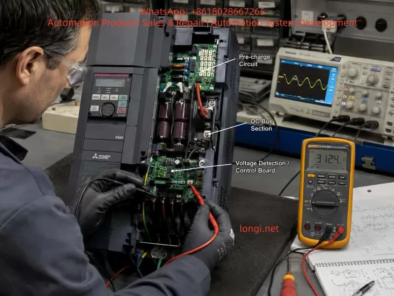
2. What Does E.UVT Mean?
E.UVT stands for:
Undervoltage Trip
It means:
The inverter has detected that the DC bus voltage has dropped below the allowable operating threshold and has activated protection.
For a 400V-class inverter:
The approximate DC bus voltage can be calculated as:
DC voltage ≈ AC voltage × 1.414
For example:
380VAC × 1.414 ≈ 537VDC
Normally, the FR-F840 DC bus voltage should be approximately:
500–560VDC
depending on the actual input voltage.
If the DC bus voltage decreases significantly, for example:
300VDC
or lower, the control system determines that the inverter cannot safely drive the IGBT section and triggers:
E.UVT
3. Why Is “Immediate E.UVT After Power-On” Important?
The timing of the fault provides valuable diagnostic information.
There are three typical situations:
Case 1: E.UVT During Normal Operation
Example:
The inverter runs normally for several minutes and then suddenly trips.
Possible causes:
- Utility voltage fluctuation;
- Insufficient transformer capacity;
- Large load startup on the same power network;
- Loose input contactor;
- Poor cable connection.
Case 2: E.UVT During Acceleration
Possible causes:
- Excessive motor load;
- Acceleration time too short;
- DC regenerative energy problems;
- Weak power supply.
Case 3: E.UVT Immediately After Power-On
This is the most important condition.
At this moment:
- The motor has not started;
- The IGBT output is inactive;
- Load influence is minimal.
Therefore, the problem is usually located in the power supply establishment and voltage detection circuits.
The main inspection areas are:
- AC input;
- Rectifier bridge;
- Pre-charge circuit;
- DC bus capacitors;
- DC voltage detection circuit.
4. Step-by-Step Troubleshooting Procedure
Step 1: Check Three-Phase Input Voltage
First measure:
R-S
S-T
T-R
Normal values:
380–440VAC
The three phases should be balanced.
Example:
Normal:
R-S = 402V
S-T = 401V
T-R = 403V
Abnormal:
R-S = 400V
S-T = 395V
T-R = 250V
Possible causes:
- Phase loss;
- Damaged contactor;
- Loose terminal;
- Power supply problem.
5. Step 2: Measure DC Bus Voltage
This is the most important measurement.
Measure between:
P(+)

and

N(-)
Expected value:
Approximately:
500–560VDC
The result determines the troubleshooting direction.
Situation A: DC Bus Voltage Does Not Build Up
Example:
P-N = 50VDC
The inverter cannot establish the DC bus.
Possible causes:
1. Rectifier Bridge Failure
The IGBT module may be normal, but the rectifier section can still fail.
Possible faults:
- Open rectifier diode;
- Damaged rectifier module;
- Input phase failure;
- Internal connection problem.
Important:
A normal IGBT does not mean the complete power section is normal.
The rectifier and inverter sections are independent.
2. Pre-Charge Circuit Failure
Large-capacity inverters cannot directly charge large DC capacitors because the initial charging current would be extremely high.
Therefore, they use a pre-charge circuit:
AC input

↓

Rectifier bridge

↓

Pre-charge resistor

↓

DC capacitors

↓

Bypass relay/contactor

↓

Normal operation
If any of the following fail:
- Pre-charge resistor open;
- Relay does not activate;
- Relay contact burned;
- Drive circuit failure;
the DC bus cannot charge correctly, resulting in E.UVT.
Situation B: DC Bus Voltage Is Normal but E.UVT Still Appears
This situation is very common during professional repairs.
Example measurement:
P-N = 530VDC
but the inverter still displays:
E.UVT
This means:
The actual DC voltage is normal, but the control system believes the voltage is too low.
The suspected area is:
DC bus voltage detection circuit.
6. DC Bus Voltage Detection Principle
The CPU cannot directly measure 500VDC.
Therefore, the inverter uses a voltage detection circuit:
DC 500V

↓

High-voltage resistor divider

↓

Isolation circuit

↓

ADC sampling

↓

CPU calculation

↓

Protection judgment
If this circuit fails:
Actual voltage:
530VDC
Detection result:
200VDC
The CPU will incorrectly trigger:
E.UVT
Common Detection Circuit Failures
1. High-Voltage Resistor Drift
High-voltage resistors operate continuously under electrical stress.
After years of operation:
- Resistance increases;
- Resistance decreases;
- Internal cracks occur.
The voltage division ratio changes, causing incorrect measurement.
2. Optocoupler Aging
Some inverter designs use isolation components.
After long operation:
- Optical transmission efficiency decreases;
- Signal amplitude becomes incorrect.
3. Detection IC Failure
Possible problems:
- ADC input abnormality;
- Operational amplifier damage;
- Reference voltage failure.
7. Control Power Supply Problems
The control board requires stable low-voltage supplies.
Important rails include:
+5V Power Supply
Used by:
- CPU;
- Digital circuits;
- Memory.
If:
5V drops to 4.5V
the CPU may misjudge voltage signals.
+15V Power Supply
Used for:
- Gate drive circuits;
- Analog detection circuits.
+24V Power Supply
Used for:
- Relays;
- External control interfaces.
Unstable control power can cause:
- E.UVT;
- CPU errors;
- Communication faults.
8. Common Repair Mistakes
Mistake 1: Replacing the IGBT Immediately
Many technicians see a power-related alarm and replace the IGBT module.
This is often unnecessary.
The IGBT may be completely normal.
Mistake 2: Only Measuring Input Voltage
Checking:
R/S/T voltage normal
does not prove the inverter is healthy.
The technician must also check:
P-N DC bus voltage
because the failure may exist in:
- Rectification;
- Pre-charge;
- Voltage detection.
Mistake 3: Assuming a Normal Power Module Means the Main Circuit Is Good
The main power system includes:
- Rectifier;
- DC capacitors;
- Pre-charge circuit;
- Voltage detection;
- IGBT inverter.
All sections must be verified.
9. Example Repair Case: FR-F840-00620-2-60 Immediate E.UVT
Equipment
Model:
Mitsubishi FR-F840-00620-2-60
Power:
30kW
Fault:
E.UVT immediately after power-on
Inspection Process
Step 1
Three-phase input voltage checked.
Result:
Normal.
External power supply was excluded.
Step 2
IGBT module checked.
Result:
Normal.
Power module failure was excluded.
Step 3
DC bus measured.
Result:
Approximately:
530VDC
The DC bus was successfully established.
Step 4
Voltage detection circuit inspected.
Finding:
The DC voltage feedback signal was abnormal.
Cause:
High-voltage divider components had drifted from their original values.
After repairing the detection circuit:
The inverter returned to normal operation.
This case demonstrates an important principle:
An undervoltage alarm does not always mean the actual voltage is low.
The failure may exist in the measurement system.
10. Recommended Diagnostic Strategy for High-Power VFD Repair
For inverters above 30kW, technicians should follow a fixed troubleshooting sequence:
Confirm fault code

↓

Analyze fault timing

↓

Measure AC input

↓

Measure DC bus voltage

↓

Check charging circuit

↓

Check voltage detection

↓

Check control power supply

↓

Repair and test
Avoid unnecessary replacement of expensive components such as:
- IGBT modules;
- Control boards;
- Main boards.
The correct approach is:
Measure first, diagnose second, replace components last.
Conclusion
For Mitsubishi FR-F840-00620-2-60 inverters displaying E.UVT undervoltage faults, especially when the alarm occurs immediately after power-on, the troubleshooting focus should not be limited to the external power supply.
The correct diagnostic sequence is:
- Verify three-phase input voltage;
- Measure DC bus voltage;
- Check rectifier and pre-charge circuits;
- Verify DC voltage feedback detection;
- Check control board power supplies.
When the power module has already been confirmed normal, technicians should pay special attention to:
- DC bus voltage detection circuits;
- Pre-charge charging circuits;
- Control board sampling circuits.
The key principle of industrial inverter troubleshooting is:
A fault code shows what the drive detected, not necessarily where the failure occurred.
Only by combining electrical measurements, circuit understanding, and systematic analysis can technicians accurately locate faults, reduce unnecessary component replacement, and improve repair efficiency.