
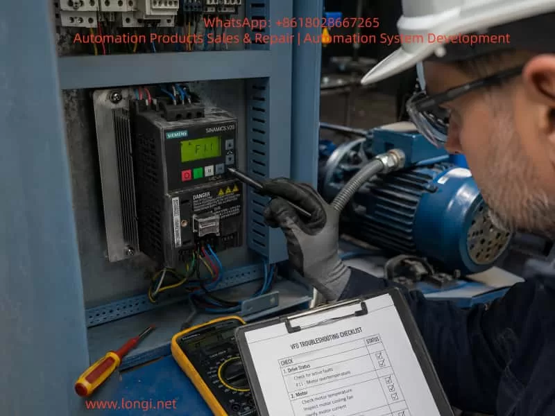
1. Introduction: Why Does SINAMICS V20 Display F11 Fault?
In industrial automation systems, Siemens SINAMICS V20 frequency converters are widely used in applications such as fans, pumps, conveyors, packaging machines, machine tools, and general-purpose drive systems. Due to their compact design, simple commissioning process, and reliable performance, V20 drives have become one of the most popular variable frequency drives for small and medium-power motor applications.
However, during operation, maintenance engineers frequently encounter one common fault:
SINAMICS V20 displays F11.
When technicians see this alarm, many immediately assume:
- The inverter power module is damaged.
- The IGBT module has failed.
- The control board is defective.
- The motor has already burned out.
In most cases, these judgments are incorrect.
The F11 fault on Siemens SINAMICS V20 means:
Motor overtemperature protection has been triggered.
The inverter has detected that the motor thermal load has exceeded the allowable limit and has stopped output to protect the motor.
According to Siemens SINAMICS V20 operating documentation, F11 belongs to the motor temperature protection category. It is related to motor overload and the internal thermal calculation model of the drive, rather than a direct indication of inverter hardware failure.
Therefore, the correct troubleshooting direction should focus on:
- Motor condition
- Mechanical load
- Motor parameters
- Operating current
- Running frequency
- Cooling conditions
Instead of replacing the inverter immediately.
2. How Does SINAMICS V20 Detect Motor Overtemperature?
2.1 Thermal Model Protection Principle
A common question from field engineers is:
“The motor does not have a temperature sensor. How does the inverter know the motor temperature?”
The answer is:
SINAMICS V20 uses an internal motor thermal model.
The drive estimates motor heating based on:
- Output current
- Operating time
- Motor parameters
- Load conditions
The basic principle is:
[
Motor\ Heating \propto I^2t
]
This means:
The larger the motor current and the longer the operating time, the greater the calculated thermal load.
When the calculated thermal value exceeds the protection limit, the inverter assumes:
The motor may be overheating and activates F11 protection.
This protection method does not require an actual temperature sensor inside the motor.
3. Why Does Low-Speed Operation Easily Cause F11?
This is one of the most common reasons for SINAMICS V20 F11 faults.
A standard asynchronous motor normally uses a shaft-mounted cooling fan.
For example:
At 50Hz operation:
A 4-pole motor runs around:
1450 rpm
The cooling fan operates at high speed, providing sufficient airflow.
However:
At 10Hz operation:
The motor speed drops to approximately:
290 rpm.
The cooling fan speed also decreases significantly.
The result:
- Cooling capacity decreases.
- Motor temperature rises.
- Copper losses continue.
- Thermal accumulation increases.
Eventually:
The V20 thermal model reaches the protection threshold and triggers F11.
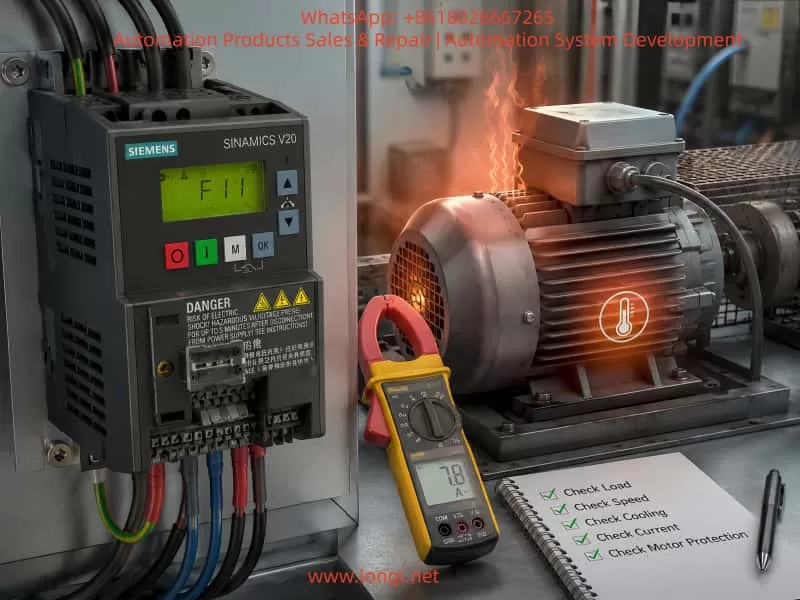
Siemens documentation specifically indicates that small motors (≤250W), especially 2-pole or 4-pole motors, may trigger this fault when operating continuously below approximately 15Hz, even if the actual motor temperature has not reached a dangerous level.
4. Main Causes of SINAMICS V20 F11 Fault
Cause 1: Actual Motor Overload
This is the most common reason.
Example:
Motor specification:
- Power: 1.5kW
- Rated current: 3.5A
Actual running condition:
- Current: 5A–6A continuously
The motor is overloaded.
The motor copper loss increases according to:
[
P=I^2R
]
If current increases by 20%, the heating effect can increase by approximately 44%.
The thermal model inside the inverter accumulates this overload condition and eventually activates F11.
Typical Mechanical Causes of Motor Overload
1. Bearing Damage
A damaged bearing increases:
- Mechanical friction
- Starting torque
- Running current
Typical symptoms:
- Abnormal noise
- Vibration
- Increased current fluctuation
Inspection method:
After power is removed:
Rotate the motor shaft manually.
A normal motor should rotate smoothly.
Problems may include:
- Tight rotation
- Mechanical resistance
- Grinding noise
2. Mechanical Jamming
Examples:
Conveyor systems:
- Chain blockage
- Roller obstruction
- Material accumulation
Pumps:
- Impeller blockage
- Valve problems
Fans:
- Blade collision
- Air duct blockage
All of these increase the required motor torque and cause excessive current.
Cause 2: Incorrect Motor Parameter Settings
SINAMICS V20 requires correct motor nameplate data.
Incorrect motor parameters can cause inaccurate thermal calculations.
Important parameters include:
| Parameter | Description |
|---|---|
| P0304 | Motor rated voltage |
| P0305 | Motor rated current |
| P0307 | Motor rated power |
| P0310 | Motor rated frequency |
| P0335 | Motor cooling method |
| P0604 | Motor temperature threshold |
| P0610 | Motor overload protection mode |
P0304 – Motor Rated Voltage
Example:
Motor nameplate:
400V
Parameter:
380V
Incorrect voltage data may affect:
- Flux calculation
- Torque performance
- Current estimation
P0305 – Motor Rated Current
This is one of the most important parameters.
Example:
Motor:
2.2kW
Rated current:
4.8A
If the parameter is incorrectly set to:
3A
or
8A
the thermal protection calculation will become inaccurate.
P0307 – Motor Power
The motor power rating must match the actual motor.
Incorrect power settings can cause:
- Wrong protection calculation
- Poor torque performance
P0310 – Motor Frequency
Most industrial motors:
50Hz
If incorrectly set:
60Hz
the magnetic flux calculation may become incorrect.
5. Step-by-Step Troubleshooting Procedure for F11
Step 1: Confirm Operating Conditions
Do not immediately reset the fault.
Record:
- Fault occurrence time
- Output frequency
- Output current
- Motor load condition
- Motor temperature
Check the actual operating current.
If current is higher than the motor nameplate rating:
Investigate the mechanical load first.
Step 2: Check Actual Motor Temperature
Use:
- Infrared thermometer
- Thermal imaging camera
Measure:
- Motor housing temperature
- Bearing temperature
- Terminal box temperature
Normal industrial motor temperature:
Approximately:
60–80°C
If the temperature exceeds:
90–100°C
real overheating is likely.
Step 3: Check Motor Cooling Condition
Inspect:
Cooling fan
Confirm:
- Fan rotation
- Airflow
- Dust accumulation
- Ventilation opening
Installation environment
Check:
- Ambient temperature
- Cabinet ventilation
- Heat sources nearby
Example:
A motor installed near:
- Heating equipment
- Furnace
- Closed enclosure
may overheat even with normal electrical load.
Step 4: Measure Motor Current
Use a clamp meter.
Measure:
- U phase current
- V phase current
- W phase current
Normal:
Three-phase current should be balanced.
Example:
Normal:
U = 4.2A
V = 4.3A
W = 4.1A
Abnormal:
U = 4A
V = 4.2A
W = 7A
Possible causes:
- Motor winding problem
- Phase imbalance
- Mechanical overload
Step 5: Verify V20 Parameters
Check:
| Parameter | Function |
|---|---|
| P0304 | Motor voltage |
| P0305 | Motor current |
| P0307 | Motor power |
| P0310 | Motor frequency |
| P0335 | Cooling method |
| P0604 | Temperature protection threshold |
| P0610 | Overload protection |
Special attention should be given to P0335.
If the motor uses:
- External cooling fan
- Forced ventilation
the cooling method setting should match the actual motor configuration.
6. Special Case: False F11 Alarm Caused by Low Frequency Operation
This is a very typical SINAMICS V20 application issue.
Example:
Equipment:
- SINAMICS V20
- 0.25kW motor
Operating frequency:
5–10Hz
Load:
Normal
After several hours:
F11 appears.
The motor is not necessarily damaged.
The reason:
The standard motor cooling fan cannot provide enough airflow at low speed.
Solutions:
Solution 1:
Increase minimum operating frequency.
Example:
Before:
5Hz
After:
15Hz
Solution 2:
Install an independent cooling fan.
This is common for:
- Conveyor systems
- Hoisting equipment
- Slow-speed mixers
Solution 3:
Adjust motor cooling-related parameters.
7. Can F11 Be Caused by a Faulty Inverter?
The probability is relatively low.
However, inverter-related causes should be considered under these conditions:
Situation 1:
A different normal motor still produces F11.
Possible causes:
- Control board problem
- Current detection abnormality
- Parameter memory error
Situation 2:
Displayed current is incorrect.
Example:
Actual current:
2A
Display:
8A
Possible causes:
- Current sensor failure
- Control board malfunction
Situation 3:
Parameter corruption
After:
- Long storage
- Electrical interference
- Incorrect operation
parameters may become abnormal.
Recommended action:
Perform:
Factory reset
then:
Complete motor commissioning again.
8. Practical Maintenance Case Study
Equipment Background
Drive:
Siemens SINAMICS V20
Fault:
F11 appears after 30 minutes operation.
Motor:
1.5kW
Operating frequency:
12Hz
Current measurement:
Near rated current.
Initial judgment:
No obvious overload.
Further inspection:
Motor installation space was too limited.
The rear of the motor was only 50mm from the wall.
The cooling fan could not obtain enough airflow.
Solution:
- Improve installation clearance.
- Clean ventilation path.
Result:
The system operated continuously for 24 hours without F11.
Final diagnosis:
The inverter was healthy.
The actual problem was insufficient motor cooling.
9. Common Mistakes During F11 Troubleshooting
Mistake 1:
Replacing the inverter immediately.
Why wrong:
F11 protects the motor, not the inverter power section.
Mistake 2:
Only performing insulation tests.
A motor can have:
- Good insulation
- Normal resistance
but still suffer from:
- Mechanical overload
- Bearing problems
- Poor cooling
Mistake 3:
Ignoring operating frequency.
Low-frequency operation must always consider cooling performance.
Mistake 4:
Increasing protection parameters blindly.
For example:
Increasing P0604 may temporarily remove alarms.
However:
The motor may actually overheat and fail.
10. SINAMICS V20 F11 Troubleshooting Summary Table
| Cause | Inspection Method | Solution |
|---|---|---|
| Mechanical overload | Measure current, inspect machine | Reduce load |
| Bearing damage | Noise and vibration inspection | Replace bearing |
| Incorrect motor parameters | Check P0304-P0310 | Correct settings |
| Low-speed operation | Check frequency | Increase minimum speed |
| Poor cooling | Temperature measurement | Improve ventilation |
| Motor undersized | Compare motor/load rating | Select proper motor |
| Current detection error | Compare actual/displayed current | Repair inverter |
11. Conclusion
The SINAMICS V20 F11 fault is fundamentally a:
Motor thermal protection fault.
It does not directly indicate:
- IGBT failure
- Power module damage
- Control board failure
The majority of F11 cases are caused by:
- Motor overload;
- Low-speed operation with insufficient cooling;
- Incorrect motor parameters;
- Mechanical resistance or blockage;
- High ambient temperature.
A correct troubleshooting strategy should follow this sequence:
Mechanical system → Motor condition → Electrical parameters → Inverter diagnosis
By following a systematic inspection process, engineers can avoid unnecessary inverter replacement, reduce downtime, and quickly identify the real root cause.
For industrial maintenance engineers, understanding the protection logic behind SINAMICS V20 F11 is far more valuable than simply memorizing the fault code. Effective troubleshooting is not about eliminating the alarm—it is about identifying and correcting the condition that caused the alarm in the first place.