
1. Fault Overview
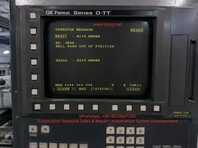
On a CNC lathe equipped with a GE Fanuc Series O-TT control, the operator screen may display an OPERATOR MESSAGE such as:
NO. 2056
BELL WASH OUT OF POSITION
The screen may also show channel-related information such as:
HEAD1 : 0119 N0000
HEAD2 : 0219 N0000
This indicates that the machine is most likely a twin-turret, twin-channel CNC lathe, not a simple single-channel turning machine. The alarm is not a standard Fanuc servo alarm, spindle alarm, or CNC main board alarm. It is a machine-builder PMC/operator message, generated by the ladder logic written for the machine’s peripheral mechanisms.
The key phrase is:
BELL WASH OUT OF POSITION
This can be understood as:
The Bell Wash mechanism is not in the correct position.
“Bell Wash” is not a universal Fanuc standard term. It is usually a machine-builder name for a washing, flushing, spraying, or cover-type cleaning mechanism. The word “Bell” may refer to a bell-shaped cover or a moving cleaning hood, while “Wash” refers to washing or flushing.
Therefore, this alarm should not be interpreted as a general coolant pump fault, spindle cooling failure, or Fanuc CNC control failure. The real meaning is that a certain washing mechanism has not reached the required home, retracted, extended, or safe position, or the PMC has not received the correct position confirmation signal.
2. System Background: GE Fanuc Series O-TT
The GE Fanuc Series O-TT is commonly used on more complex CNC turning machines, especially those with:
- Twin turrets;
- Twin machining channels;
- Upper and lower turrets;
- One or two spindles;
- Multiple hydraulic and pneumatic auxiliary mechanisms;
- Automatic loading or unloading devices;
- Workpiece washing or flushing systems;
- Complex M-code controlled peripheral functions.
Compared with a simple single-turret lathe, a twin-channel machine has far more interlocks. One auxiliary mechanism may affect both channels. For example, if a washing cover is not retracted, it may prevent turret movement, spindle start, automatic cycle start, or work transfer.
This is why the screen may display HEAD1 and HEAD2 information. The fault may be related to one channel, or it may be a shared peripheral interlock that blocks both channels.
When diagnosing this type of alarm, the technician must consider:
- Whether the alarm is associated with HEAD1 or HEAD2;
- Whether the Bell Wash mechanism serves one channel or both channels;
- Whether the machine is in manual, automatic, or interrupted cycle mode;
- Whether the alarm blocks turret movement, spindle rotation, loading, or washing operation;
- Whether both channels require a safe-position confirmation signal before the alarm clears.
3. Meaning of “BELL WASH OUT OF POSITION”
The term Bell Wash may refer to several possible mechanisms depending on the machine builder’s design:
- A bell-shaped workpiece washing cover;
- A chuck or spindle-area flushing mechanism;
- A movable coolant or washing nozzle;
- A cleaning arm driven by a pneumatic cylinder;
- A washing unit used during automatic loading/unloading;
- A cover or nozzle that must extend for washing and retract before machining;
- A machine-builder-specific washing device with a custom name.
The important part of the message is OUT OF POSITION. This means the PMC does not see the required position state.
The expected position may be:
- Home position;
- Retracted position;
- Extended washing position;
- Safe position;
- Cycle-ready position;
- A valid combination of position sensor signals.
In most machines, the Bell Wash unit will have at least one position confirmation switch. Many designs use two switches:
| Mechanism Status | Possible Sensor State |
|---|---|
| Bell Wash retracted / home | Home or retract sensor ON |
| Bell Wash extended / wash position | Forward or wash sensor ON |
A typical two-sensor logic may be:
| Bell Wash Status | Home Sensor | Forward Sensor |
|---|---|---|
| Retracted home position | ON | OFF |
| Extended wash position | OFF | ON |
| Stuck in middle position | OFF | OFF |
| Sensor logic abnormal | ON | ON |
If the PMC expects the mechanism to be home but the home signal is missing, it may generate BELL WASH OUT OF POSITION.
If the PMC commands the mechanism to the washing position but the forward signal does not appear, it may also generate the same message.
If both sensors are ON at the same time, the ladder logic may judge the status as contradictory and raise an alarm.
4. Why This Is a PMC Interlock Alarm
This type of fault is normally controlled by the machine’s PMC logic.
The typical control sequence is:
- CNC or PMC issues a command.
- A PMC output drives a solenoid valve.
- The solenoid valve actuates an air cylinder or hydraulic cylinder.
- The Bell Wash mechanism moves.
- A proximity switch or limit switch confirms position.
- The signal returns to a PMC input.
- The PMC confirms that the motion is complete.
- The next machine step is allowed.
If any part of this sequence fails, the machine can report an operator message.
The fault chain includes:
- Mechanical movement;
- Pneumatic or hydraulic pressure;
- Solenoid valve action;
- Position sensor switching;
- Wiring to the I/O module;
- PMC input recognition;
- Channel interlock logic.
This is why replacing Fanuc CNC boards or changing CNC parameters is usually the wrong first step.
5. Difference from a Chuck Jaw Sensor Alarm
A machine may previously have had a chuck jaw or chuck clamping sensor alarm. That type of fault and the Bell Wash alarm are different in component location, but similar in logic.
| Item | Chuck Jaw Sensor Alarm | Bell Wash Position Alarm |
|---|---|---|
| Component | Chuck clamp/unclamp mechanism | Washing cover/nozzle/arm |
| Control logic | PMC ladder | PMC ladder |
| Feedback | Clamp/unclamp sensor | Home/forward Bell Wash sensor |
| Actuator | Hydraulic cylinder or chuck drawtube | Air cylinder, hydraulic cylinder, or solenoid |
| Common faults | Sensor misalignment, hydraulic failure, wiring fault | Mechanism stuck, low air pressure, sensor failure, wiring fault |
| Safety role | Chuck clamping confirmation | Mechanism clearance and cycle interlock |
Both alarms belong to the same broad category: machine-side position confirmation faults.
The CNC is waiting for a position signal. If the signal is missing, wrong, or contradictory, the PMC stops the machine and displays an operator message.
6. Common Causes
6.1 Bell Wash Mechanism Not Returned to Home Position
The simplest cause is that the mechanism is physically out of position.
Possible reasons include:
- Chips blocking the washing cover;
- Coolant sludge around the sliding mechanism;
- Deformed washing nozzle or cover;
- A workpiece interfering with the washing unit;
- A bent cylinder rod;
- Dry or rusted guide rods;
- Loose linkage;
- Shifted mechanical stop;
- Incorrect manual movement after maintenance;
- Machine guard deformation.
In this case, the sensor and wiring may be normal. The problem is mechanical: the Bell Wash device has not actually reached the position required by the PMC.
The technician must inspect the actual mechanism before replacing electrical parts.
6.2 Low Air Pressure or Hydraulic Pressure
Many Bell Wash mechanisms are pneumatic because the motion is light, fast, and repetitive. If air pressure is low, the cylinder may move only partially and fail to reach the end position.
Possible pneumatic causes include:
- Low main air supply;
- Regulator pressure set too low;
- Air valve not fully opened;
- Air hose disconnected;
- Bent or blocked air tubing;
- Cylinder seal leakage;
- Solenoid valve leakage;
- Flow control valve closed too much;
- Muffler blocked;
- Water separator clogged;
- Worn air cylinder.
If the mechanism moves slowly, stops halfway, or lacks force, the pressure system must be checked before the sensor circuit.
The same principle applies if the unit is hydraulically driven. In that case, check hydraulic pressure, solenoid valves, cylinder movement, oil level, filters, and leakage.
6.3 Solenoid Valve Not Switching
The Bell Wash unit is usually controlled by a solenoid valve. If the valve does not switch, the cylinder will not move.
Common causes include:
- Burned solenoid coil;
- No coil voltage;
- Loose connector;
- Sticking valve spool;
- Contaminated valve body;
- Faulty output relay;
- No PMC output;
- Blown fuse;
- 24 VDC supply problem.
Field checks include:
- Observe whether the valve LED turns ON.
- Listen for the clicking sound of the coil.
- Measure voltage at the coil.
- Press the manual override on the valve.
- Watch whether the cylinder moves.
- Check exhaust air from the valve ports.
If the mechanism works when the manual override is pressed, the air supply, valve body, and cylinder are probably functional, and the fault may be in the electrical command or PMC output.
If the mechanism does not move even with manual override, check air supply, valve body, cylinder, and mechanical binding.
6.4 Misadjusted Position Sensor
The Bell Wash mechanism usually uses one or more position sensors, such as:
- Inductive proximity switch;
- Magnetic cylinder switch;
- Mechanical limit switch;
- Photoelectric sensor;
- Microswitch.
These sensors are exposed to vibration, coolant, oil, chips, and occasional mechanical impact. A slight shift in sensor position can prevent the switch from detecting the target.
Typical symptoms include:
- The mechanism appears to move correctly;
- The alarm occurs intermittently;
- The sensor LED is unstable;
- The alarm disappears when the mechanism is pushed manually;
- The alarm disappears after adjusting the sensor gap;
- Vibration makes the alarm more frequent.
The sensor should be adjusted so that it is not at the edge of its detection range. After adjustment, the machine should be tested repeatedly.
6.5 Damaged Position Sensor
The sensor itself may also fail.
Typical symptoms include:
- 24 VDC supply is present but there is no output;
- LED never turns ON;
- LED remains ON all the time;
- Output voltage does not change;
- Signal changes when the cable is moved;
- Sensor head is cracked or damaged;
- Sensor face is covered with metal chips or oil sludge.
When replacing a sensor, the following specifications must match:
- Voltage;
- NPN or PNP output;
- Normally open or normally closed logic;
- Two-wire, three-wire, or four-wire type;
- Sensing distance;
- Thread size and mounting style;
- Protection rating;
- Cable type and wiring color.
Using the wrong sensor type may reverse the logic or make the alarm harder to diagnose.
6.6 Wiring or Terminal Fault
Older Fanuc machines often suffer from wiring faults in peripheral circuits. The Bell Wash unit is usually located near coolant, chips, and moving machine parts, so cables and connectors are vulnerable.
Common wiring problems include:
- Broken sensor power wire;
- Broken sensor output wire;
- Loose 0 V common line;
- Oil-contaminated connector;
- Loose terminal strip;
- Oxidized relay contact;
- Loose I/O module connector;
- Wrong reconnection after maintenance;
- Damaged cable insulation.
The key diagnostic method is to compare three points:
- Sensor LED condition;
- Sensor output voltage;
- Corresponding Fanuc PMC X input state.
If the sensor LED changes but the PMC input does not change, the signal is not reaching the CNC I/O. The technician must trace the wiring from the sensor to the terminal strip and then to the I/O module.
6.7 PMC Input or Output Fault
If the mechanism, valve, sensor, and wiring are confirmed good, then the I/O module or PMC control path should be considered.
Possible issues include:
- Defective PMC input point;
- Defective PMC output point;
- I/O Link problem;
- Interface board fault;
- Common power supply problem;
- Relay fault;
- Fuse fault;
- Incorrect keep relay condition;
- Ladder condition not satisfied.
However, Fanuc board failure should not be the first assumption. In most real field cases, this type of alarm is caused by mechanical sticking, air pressure, sensors, valves, wiring, or terminals.
7. Diagnostic Procedure
Step 1: Confirm When the Alarm Appears
Record when the alarm occurs:
- Immediately after power-on;
- After reset;
- During manual operation;
- During automatic cycle start;
- Before spindle start;
- Before turret movement;
- After an M-code command;
- After washing operation;
- In HEAD1 or HEAD2 operation.
If the alarm appears immediately after power-on, focus on the home/retracted signal.
If it appears after a washing command, focus on the forward or completed-position signal.
If it appears during automatic cycle start, focus on safe-position interlocks.
If it appears in one channel only, check the relationship between HEAD1, HEAD2, and shared peripherals.
Step 2: Locate the Bell Wash Mechanism
Since “Bell Wash” is a machine-builder name, the physical unit must be identified on the machine.
Check these areas:
- Chuck area;
- Main spindle area;
- Sub-spindle area;
- Upper/lower turret area;
- Workpiece transfer area;
- Automatic loader area;
- Machine door area;
- Coolant flushing unit;
- Small pneumatic cover or nozzle mechanism.
In the electrical drawings, look for terms such as:
- BELL WASH;
- WASH;
- BW;
- B.W.;
- WASH HOME;
- WASH EXTEND;
- WASH RETRACT;
- WASH POSITION;
- IN POSITION;
- CYLINDER;
- SOLENOID.
Once located, inspect:
- Cylinder;
- Solenoid valve;
- Proximity switch;
- Limit switch;
- Sensing target;
- Mechanical stop;
- Linkage;
- Air or hydraulic tubing;
- Cable route.
Step 3: Check for Mechanical Obstruction
With the machine in a safe condition, inspect whether the mechanism is stuck between positions.
Check for:
- Chips;
- Coolant sludge;
- Workpiece interference;
- Bent bracket;
- Bent cylinder rod;
- Damaged guide;
- Loose linkage;
- Worn sliding parts;
- Impact damage;
- Interference with turret, chuck, or guard.
If the mechanism is mechanically stuck, correct the mechanical fault first. Do not force the valve or repeatedly command the mechanism, because this may damage the cylinder, sensor, bracket, or surrounding components.
Step 4: Check Air or Hydraulic Pressure
If pneumatic, check:
- Main air pressure;
- Regulator pressure;
- Air gauge;
- Air shutoff valve;
- Water separator;
- Air hose;
- Flow control valve;
- Cylinder leakage;
- Valve exhaust.
A normal pneumatic movement should be quick and positive. Slow or incomplete motion usually indicates pressure, leakage, or flow restriction.
If hydraulic, check:
- Hydraulic pressure;
- Oil level;
- Filters;
- Solenoid valve;
- Cylinder stroke;
- Leakage;
- Return line restriction.
Step 5: Check the Solenoid Valve
Identify the solenoid valve that controls the Bell Wash mechanism.
Check:
- Whether the valve LED turns ON when commanded;
- Whether coil voltage is present;
- Whether the valve clicks;
- Whether manual override moves the mechanism;
- Whether the cylinder moves fully;
- Whether air exhaust changes.
Diagnostic interpretation:
| Result | Likely Direction |
|---|---|
| Coil has voltage but valve does not move | Valve spool stuck, coil fault, air problem |
| Coil has no voltage but PMC output is ON | Wiring, relay, fuse, terminal issue |
| Coil has no voltage and PMC output is OFF | Ladder condition not satisfied |
| Manual override works | Air circuit and mechanism mostly OK; check electrical control |
| Manual override does not work | Check air supply, valve, cylinder, mechanical binding |
Step 6: Check Position Sensors
Find the home and forward position sensors of the Bell Wash unit.
Observe sensor LEDs while moving the mechanism.
Typical logic:
| Mechanism Status | Home Sensor | Forward Sensor |
|---|---|---|
| Retracted | ON | OFF |
| Extended | OFF | ON |
| Stuck halfway | OFF | OFF |
| Abnormal logic | ON | ON |
If the mechanism is physically home but the home LED is OFF, check sensor distance, target position, sensor power, and sensor condition.
If the LED is ON but the alarm remains, check PMC input.
If both sensors are ON, check sensor placement, target design, or wiring short.
If both sensors are OFF, check whether the mechanism is really between positions or whether sensor power is missing.
Step 7: Check Fanuc PMC Diagnosis
The most reliable electrical confirmation is to check the PMC input state.
The general operation path is usually:
- Press SYSTEM.
- Enter PMC.
- Select PMCDGN or PMC DIAGNOSIS.
- Display the related X input address.
- Operate the Bell Wash mechanism.
- Observe whether the input bit changes.
If the electrical drawings are available, use them to identify the exact X input address. Without drawings, an experienced technician can observe changing X bits while operating the mechanism, but this must be done carefully, especially on a twin-channel machine where many signals may change simultaneously.
8. Repair Methods
8.1 Clean and Restore the Mechanism
If chips or sludge block the mechanism:
- Remove chips;
- Clean coolant sludge;
- Clean the guide;
- Inspect nozzle and cover;
- Lubricate sliding parts;
- Repair bent brackets;
- Confirm there is no workpiece interference;
- Return the mechanism to its proper home position.
After cleaning, cycle the unit repeatedly.
8.2 Restore Air or Hydraulic Supply
For pneumatic systems:
- Adjust air pressure;
- Replace damaged air hoses;
- Clean the water separator;
- Adjust flow controls;
- Repair air leakage;
- Replace cylinder seals;
- Replace faulty solenoid valves.
For hydraulic systems:
- Check hydraulic pressure;
- Check oil level;
- Replace filters;
- Check valve operation;
- Repair leakage;
- Confirm cylinder stroke.
8.3 Adjust Position Sensors
If the mechanism reaches position but the sensor does not switch:
- Clean the sensor face;
- Clean the sensing target;
- Adjust the sensing distance;
- Avoid edge-of-range adjustment;
- Tighten the bracket;
- Confirm stable LED switching;
- Verify corresponding PMC input change.
Do not rely only on the LED. The signal must reach the PMC input.
8.4 Replace Defective Sensors
If the sensor is defective, replace it with the correct type.
Confirm:
- Voltage;
- NPN/PNP type;
- NO/NC logic;
- Wiring system;
- Sensing distance;
- Mechanical size;
- Cable and connector style;
- Protection rating.
After replacement, test both manual and automatic operation.
8.5 Repair Wiring
If the sensor output is good but PMC input is missing:
- Tighten terminals;
- Clean connectors;
- Replace damaged cables;
- Check intermediate relays;
- Check I/O module terminals;
- Measure 24 VDC and 0 V;
- Confirm wire numbers;
- Eliminate loose or intermittent connections.
8.6 Check I/O and PMC Signals
If all external components are good:
- Check whether the PMC input responds;
- Check whether the PMC output activates the valve;
- Check I/O module power;
- Check common terminals;
- Check fuses;
- Check relays;
- Check connector condition;
- Compare with known good input or output points.
PMC ladder modification should not be attempted without correct documentation and proper authorization.
9. Why Parameters Should Not Be Changed First
When BELL WASH OUT OF POSITION appears, the following actions should not be the first response:
- Changing CNC parameters;
- Initializing the control;
- Clearing PMC data;
- Replacing the Fanuc main board;
- Permanently shorting sensors;
- Bypassing the alarm;
- Forcing automatic cycle;
- Forcing spindle or turret movement.
This is a peripheral position interlock alarm. Bypassing it may allow a washing cover, nozzle, or cleaning arm to remain in the path of a turret, spindle, chuck, or workpiece. On a twin-channel lathe, that can cause serious mechanical collision.
Temporary signal simulation is only acceptable for controlled troubleshooting by qualified personnel, with the machine made safe and original wiring restored immediately after testing.
10. Special Considerations on Twin-Channel Lathes
A GE Fanuc Series O-TT machine can have complex synchronization between channels.
Important points include:
- HEAD1 and HEAD2 relationship
One mechanism may be commanded by one channel but required as a safe interlock by both channels. - M-code waiting logic
One channel may wait for a Bell Wash complete signal while the other channel waits for synchronization. - Turret interference area
If the Bell Wash unit is not retracted, it may block upper or lower turret movement. - Spindle and sub-spindle interlocks
The washing mechanism may be related to chuck cleaning, work transfer, or sub-spindle handling. - Automatic loading/unloading
If the machine has a loader, the Bell Wash position may be part of the loading sequence. - Signal stability
Intermittent sensor signals may stop automatic operation even if manual operation appears normal.
After repair, the machine must be tested not only in manual mode but also in automatic operation, preferably with low-speed dry run and careful observation.
11. Post-Repair Verification
After repair, verify the complete sequence:
- Reset the alarm.
- Manually extend the Bell Wash mechanism.
- Manually retract the Bell Wash mechanism.
- Observe sensor LEDs.
- Observe PMC input status.
- Check cylinder movement speed.
- Check for mechanical interference.
- Perform a dry run.
- Test HEAD1 operation.
- Test HEAD2 operation.
- Test related M-codes.
- Confirm spindle, turret, and automatic cycle recovery.
- Repeat several cycles to ensure stability.
If the alarm clears in manual mode but returns in automatic mode, check program sequence, M-code completion signals, PMC timers, and twin-channel synchronization logic.
12. Field Repair Conclusion
When a GE Fanuc Series O-TT twin-channel lathe displays:
NO. 2056 BELL WASH OUT OF POSITION
the most likely meaning is:
The Bell Wash washing mechanism is not in the position required by the CNC/PMC, or the correct position confirmation signal is not reaching the PMC input.
This is not normally a Fanuc CNC main board fault. It is not a standard coolant pump alarm. It is not necessarily a spindle cooling problem.
The most likely fault points are:
- Bell Wash mechanism blocked by chips, sludge, or a workpiece;
- Washing cover, nozzle, or arm not returned home;
- Low air pressure causing incomplete cylinder movement;
- Solenoid valve not switching;
- Cylinder leakage or sticking;
- Home or forward position sensor misadjusted;
- Proximity switch or limit switch damaged;
- Sensor cable broken or terminal loose;
- PMC input not receiving the signal;
- Twin-channel interlock condition not satisfied.
The correct troubleshooting method is to start from the physical mechanism, then check air or hydraulic supply, solenoid valve, sensors, wiring, and PMC inputs.
13. Summary
BELL WASH OUT OF POSITION is a typical peripheral mechanism position alarm on older twin-channel Fanuc CNC lathes. The key diagnostic point is not the CNC control itself, but the relationship between the washing mechanism and the PMC interlock logic.
The correct principle is:
First confirm whether the mechanism is physically in position. Then confirm whether the sensor detects that position. Finally confirm whether the PMC receives the signal.
The practical sequence is:
- Locate the Bell Wash mechanism.
- Check for mechanical blockage.
- Check air or hydraulic pressure.
- Check the solenoid valve.
- Check position sensors.
- Check wiring.
- Check Fanuc PMC inputs.
- Verify both HEAD1 and HEAD2 automatic operation.
A reliable repair must restore the real movement and true position feedback of the Bell Wash mechanism. Long-term bypassing, shorting, or disabling the alarm is unsafe, especially on a twin-turret/twin-channel lathe where one misplaced auxiliary device can cause turret collision, spindle interference, or automatic cycle failure.