
The Delta VFD-L series is a widely used compact AC motor drive designed for small conveyor systems, fans, pumps, laboratory equipment, textile auxiliary mechanisms, packaging machines, and other light-duty speed control applications. Because the VFD-L family includes multiple generations, different power ranges, and different panel structures, technicians often confuse manuals from different versions during troubleshooting. One of the most common misunderstandings involves the control method selection system. Early 25W–100W VFD-L models used a 7-position DIP switch for selecting operating modes, while newer 0.2kW, 0.4kW, and 0.75kW versions with LED keypads rely primarily on parameter settings instead of external DIP switches.
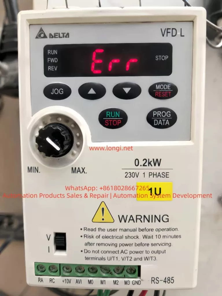
In actual field maintenance, a common symptom is that the user can enter the parameter menu, browse parameters, and even modify displayed values, but when pressing the PROG/DATA key to save the new setting, the inverter immediately displays “Err”. In many cases, this does not indicate a damaged power module or motor fault. Instead, it means the drive is refusing the parameter write operation. On Delta VFD-L drives, parameter save errors are most commonly related to operation status restrictions, parameter protection locks, read-only parameters, external control commands, or control board memory issues.
Understanding the Different VFD-L Versions
One of the first steps in troubleshooting is identifying the exact VFD-L version. Not all VFD-L models use DIP switches for control mode selection.
Older 25W–100W VFD-L models include a 7-position DIP switch used for:
- Maximum output frequency selection
- Reverse rotation prohibition
- Torque setting
- Electronic thermal relay configuration
- Operation command source selection
- Communication mode selection
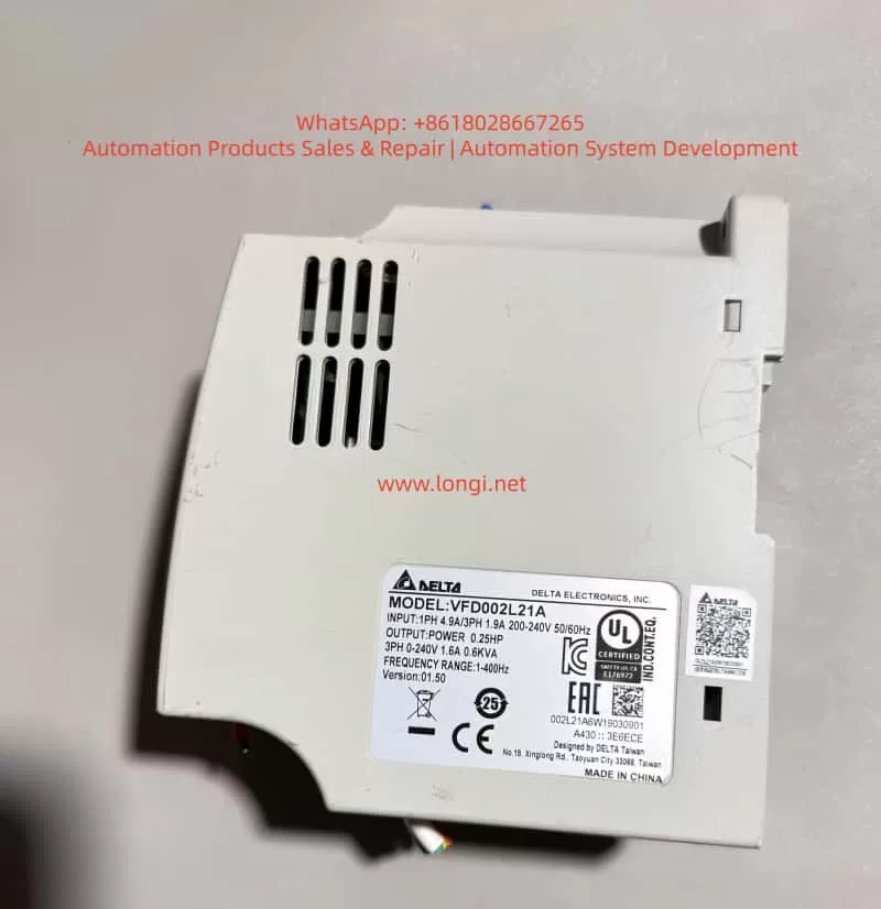
However, larger VFD-L models such as:
- VFD002L21A (0.2kW)
- VFD004L21A (0.4kW)
- VFD007L21A (0.75kW)
- VFD015L21A (1.5kW)
- VFD022L21A (2.2kW)
use a parameter-based configuration system instead. These models include:
- LED digital display
- MODE/RESET button
- PROG/DATA button
- RUN/STOP button
- Up/down keys
- Frequency adjustment potentiometer
- RS-485 communication interface
For these units, operation mode selection is handled through parameter groups, especially Group 2 parameters, rather than a physical 7-position DIP switch.
Therefore, if a technician attempts to locate a DIP switch inside a parameter-based VFD-L model and cannot find one, this is completely normal. The correct troubleshooting direction is through parameter configuration.
What “Err” Actually Means
On Delta VFD-L drives, “Err” generally means the parameter write operation has been rejected. It is not a fixed hardware alarm code like OC (overcurrent) or OV (overvoltage). Instead, it indicates the current operation is not permitted under the present conditions.
Common causes include:
- Attempting to modify parameters while the inverter is running
- Parameter protection lock enabled
- Trying to modify read-only parameters
- Entering a value outside the allowed range
- External control logic preventing changes
- EEPROM or control board memory failure
Among these possibilities, parameter protection is often overlooked because users can still browse parameters and change displayed values temporarily. However, the drive only checks write permission when the user attempts to save the parameter. If parameter protection is active, the display will show “Err” during the save operation.
Parameter 0-07 and Parameter Locking
On parameter-based VFD-L models, parameters 0-07 and 0-08 are associated with password protection.
- 0-07: Password unlock / parameter protection entry
- 0-08: Password configuration parameter
When parameter 0-07 displays d1, it means parameter protection is enabled. Under this condition, the drive allows parameter browsing but blocks write operations. Therefore, attempts to save changes to parameters such as 2-00 or 2-01 will result in “Err”.
This is extremely important because many technicians mistakenly believe the inverter is malfunctioning, while the drive is simply enforcing parameter protection rules.
If 0-07 shows:
d0 = unlocked
d1 = locked
then parameter modification will be blocked until the correct password is entered.
Why Parameters 2-00 and 2-01 Commonly Trigger “Err”
Group 2 parameters define the operating method of the VFD-L.
Parameter 2-00: Frequency Command Source
This parameter determines where the speed reference comes from. Possible sources include:
- Digital keypad
- Analog voltage input (AVI)
- Current input (4–20mA)
- Built-in VR potentiometer
- RS-485 communication
Parameter 2-01: Operation Command Source
This parameter determines where the RUN/STOP command originates.
Typical options include:
d0 = digital keypad
d1/d2 = external terminals
d3/d4 = RS-485 communication
If the goal is panel operation, the standard configuration is:
2-01 = d0
which means the RUN/STOP command comes from the keypad.
If the user wants to control speed using the front potentiometer, then:
2-00 = d3
which means frequency reference comes from the drive’s built-in VR knob.
If speed should be adjusted using the arrow keys instead:
2-00 = d0
In practice, when parameter protection is active, the drive still allows the user to navigate to these parameters and temporarily modify displayed values. However, pressing PROG/DATA to save causes “Err” because the actual write operation is blocked.
Therefore, repeatedly attempting to modify 2-00 and 2-01 is pointless until the parameter lock issue is resolved.
Another Common Cause: Attempting Changes While Running
Some VFD-L parameters can only be modified when the inverter is stopped. Parameters marked with the “a” symbol in the manual are adjustable during operation, while unmarked parameters generally require the inverter to be idle.
Parameters related to operation mode, command source, and maximum frequency are typically restricted during RUN status.
Even if the motor is not visibly rotating, the inverter may still consider itself in a RUN condition if external terminals remain active.
For example:
M0 = Forward Run
M1 = Reverse Run
GND = Common
If M0 and GND remain shorted by an external switch, relay, or PLC output, the inverter may reject parameter modifications.
Therefore, before troubleshooting “Err”, technicians should:
- Stop the inverter completely
- Remove external RUN commands
- Disconnect M0/M1 control wiring temporarily
- Power cycle the inverter
- Retry parameter modification
If “Err” persists after complete stop conditions are confirmed, parameter lock becomes the primary suspect.
Relationship Between External Control and Keypad Control
VFD-L control terminals typically include:
- RA
- RC
- +10V or +15V
- AVI
- M0
- M1
- M2
- M3
- GND
Default functions are usually:
M0 = Forward/Stop
M1 = Reverse/Stop
M2 = Reset
M3 = Multi-step speed
GND = Digital common
If parameter 2-01 is configured for external terminal control, the drive ignores the keypad RUN/STOP button and waits for terminal signals instead.
Therefore, if a technician presses RUN/STOP and nothing happens, this does not automatically mean the keypad is defective. The inverter may simply be configured for external control.
When combined with parameter protection, this creates a confusing situation:
- Keypad RUN/STOP does not work
- Parameter changes produce “Err”
- User assumes hardware failure
In reality, the inverter may simply be:
- Locked by parameter protection
- Configured for external control
Correct Troubleshooting Sequence
Step 1: Identify the Correct Model
Confirm whether the drive is:
- DIP-switch-based old version
or - Parameter-based keypad version
Never mix manuals from different VFD-L generations.
Step 2: Ensure Complete Stop Condition
Stop the inverter completely.
Disconnect:
- M0
- M1
- External PLC outputs
- Relay control wiring
to prevent hidden RUN commands.
Step 3: Power Cycle the Drive
Turn power OFF.
Wait until the display fully disappears and DC bus capacitors discharge.
Then power ON again.
Step 4: Check Parameter 0-07
If:
0-07 = d1
then parameter protection is active.
This immediately explains the “Err” message during saves.
Step 5: Test Another Writable Parameter
Try modifying a simple writable parameter such as:
- acceleration time
- deceleration time
- display mode
If all writable parameters still produce “Err”, continue investigating parameter lock or EEPROM issues.
Step 6: Configure Keypad Operation
For keypad RUN/STOP operation:
2-01 = d0
For front potentiometer speed control:
2-00 = d3
For keypad arrow-key speed control:
2-00 = d0
Step 7: Functional Testing
Return to the main display.
Set a low frequency such as:
- 5Hz
- 10Hz
Press RUN/STOP and verify:
- output frequency
- motor direction
- running current
If motor direction is reversed, swap any two motor output phases.
Distinguishing Password Lock from EEPROM Failure
Not all “Err” conditions are caused by password protection.
Signs of Password Lock
- 0-07 displays d1
- All writable parameters produce “Err”
- Browsing parameters still works
Signs of EEPROM or Memory Failure
- 0-07 displays d0
- Inverter fully stopped
- Writable parameters still cannot save
- Parameters reset after power loss
- Save operation intermittently succeeds or fails
Under these conditions, technicians should inspect:
- EEPROM IC
- Control board supply voltage
- Crystal oscillator
- Reset circuitry
- MCU peripheral circuits
Common Troubleshooting Mistakes
Mistake 1: Using the Wrong Manual
Technicians often assume every VFD-L uses DIP switches because they found a DIP-switch manual online.
This is incorrect for keypad-type VFD-L models.
Mistake 2: Misidentifying PCB Connectors as DIP Switches
Rows of black connectors or headers are often mistaken for DIP switches.
Real DIP switches have:
- movable sliders
- ON markings
- numbered positions
Mistake 3: Ignoring Parameter 0-07
Many technicians repeatedly attempt to modify 2-00 and 2-01 without checking parameter protection status.
Mistake 4: Modifying Parameters While RUN Command Exists
External terminal commands may remain active even when the motor appears stopped.
Mistake 5: Assuming Factory Reset Bypasses Password Protection
Factory reset functions may also be blocked under parameter protection.
Mistake 6: Failing to Record Original Parameters
Always document critical parameters before modification:
- 2-00
- 2-01
- acceleration/deceleration times
- motor ratings
- terminal functions
This prevents accidental loss of original machine configuration.
Recommended Final Configuration for Keypad Operation
For standard keypad-controlled operation:
2-01 = d0
2-00 = d3
Meaning:
- RUN/STOP controlled by keypad
- Speed controlled by front potentiometer
For keypad operation with arrow-key frequency control:
2-01 = d0
2-00 = d0
If the original machine was PLC-controlled or relay-controlled, technicians should avoid permanently changing operation mode without understanding the machine’s original logic.
Conclusion
When a Delta VFD-L inverter displays “Err” while saving parameters, the problem is not necessarily a damaged inverter. On keypad-based VFD-L models, the most critical diagnostic point is parameter 0-07. If 0-07 displays d1, parameter protection is active, and save operations will be rejected until the correct password is entered.
For keypad operation, the correct configuration is typically:
2-01 = d0
2-00 = d3
or:
2-01 = d0
2-00 = d0
depending on whether frequency is controlled by the potentiometer or keypad buttons.
If the inverter remains unable to save parameters even when unlocked and stopped, technicians should proceed to EEPROM, storage circuitry, and control board diagnostics. Proper troubleshooting requires a structured sequence:
- identify the correct model
- confirm stop condition
- check parameter protection
- verify writable parameters
- configure operation mode
- investigate hardware memory faults if necessary
Following this process prevents simple parameter lock issues from being misdiagnosed as major hardware failures and avoids confusion between different VFD-L generations.