
Handheld XRF analyzers are widely used for alloy identification, scrap metal sorting, incoming material inspection, PMI testing, and field-grade composition screening. The InnoV-X / Innov-X Systems Alpha series is an older generation handheld XRF platform commonly used in alloy analysis applications. Although the instrument is compact, its internal structure includes an X-ray tube, high-voltage power supply, detector, preamplifier, digital pulse processing circuit, power management system, and PDA or embedded control terminal. After years of field use, these instruments may develop standardization failures, low count rate faults, unstable results, abnormal spectra, or poor repeatability.
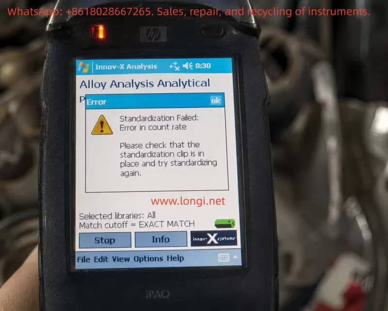
A typical fault case is an InnoV-X Alpha series handheld XRF analyzer showing the following message during standardization in Alloy Analysis mode:
Standardization Failed: Error in count rate
The instrument also prompts the operator to check whether the standardization clip is in place. In the information screen, the following diagnostic values are displayed:
| Item | Measured Value | Expected Value |
|---|---|---|
| Total counts | 474 | 1966 |
| Test resolution | 187 | 176 |
| Peak check Fe | 327.1 | 326 |
| Peak check Mo | 887.0 | 888 |
These values are very important. They show that the analyzer is not completely dead, and the problem is not caused by the alloy library or match cutoff setting. The main fault is that the total count rate during standardization is far lower than expected.
In XRF analysis, a low count rate usually means that the detector is receiving insufficient effective X-ray fluorescence signal. The cause may be in the standardization clip, analyzer window, X-ray tube output, shutter, collimator, detector, or signal-processing chain.
1. What Standardization Does in a Handheld XRF Analyzer
Many users misunderstand standardization as a normal software setting. In fact, standardization is a critical self-check and normalization process before reliable XRF measurement.
During XRF analysis, the X-ray tube emits primary X-rays onto the sample or standardization target. The atoms in the material generate characteristic fluorescent X-rays. The detector receives these signals and converts them into an energy spectrum. The software then calculates elemental composition based on peak position, peak intensity, background, and calibration algorithms.
Standardization is used to confirm several key conditions:
The X-ray tube must have enough output.
The detector must receive sufficient counts.
The energy scale must not be seriously shifted.
The characteristic peaks must appear at the correct positions.
The detector resolution must still be within an acceptable range.
The instrument must be normalized to its current operating condition.
For the InnoV-X Alpha series, standardization normally requires a dedicated standardization clip or check standard installed over the analyzer window. This clip contains a known standard material. The analyzer uses this known target to check whether the measuring system is working correctly.
Therefore, when the instrument says:
Please check that the standardization clip is in place and try standardizing again
it is not just a general reminder. The software is detecting that the expected XRF signal is too weak, similar to the situation where the standardization clip is missing, not seated properly, or blocked.
2. Why This Is a Count Rate Fault, Not a Library Problem
The core error is:
Standardization Failed: Error in count rate
The diagnostic screen shows:
Total counts: 474
Expected counts: 1966
The actual count is only about 24% of the expected value. This difference is too large to ignore. It means the analyzer is receiving only a small fraction of the signal it should receive during standardization.
The screen also shows:
Selected libraries: All
Match cutoff = EXACT MATCH
These settings are related to alloy grade matching after a measurement has been taken. They affect which alloy libraries are searched and how strictly the software matches the measured composition to known alloy grades. They do not control the physical X-ray count rate during standardization.
Changing the alloy library, match cutoff, or grade database will not solve a low standardization count rate fault. The correct diagnostic direction is the XRF signal chain: standardization clip, analyzer window, X-ray tube, high-voltage supply, shutter, collimator, detector, and preamplifier.
3. Interpreting the Fe and Mo Peak Check Values
The information screen also gives peak check data:
Peak check Fe = 327.1, factory set = 326
Peak check Mo = 887.0, factory set = 888
These values are close to the factory-set positions. This means the instrument can still identify the Fe and Mo peak positions. The energy calibration is not severely shifted.
This is an important diagnostic point. If the energy scale were seriously wrong, the peaks would appear in incorrect positions, the instrument might misidentify elements, or the spectrum would be unstable. In this case, however, the Fe and Mo peak positions are close to normal.
Therefore, the main problem is not energy calibration. The instrument can still “see” the peaks, but the signal strength is too low.
A practical way to summarize this fault is:
Peak position is basically correct, but total counts are seriously low.
This points more strongly to weak excitation, blocked X-ray path, poor standardization target contact, window contamination, tube output weakness, shutter obstruction, or detector count efficiency loss.
4. Understanding the Resolution Value
The screen shows:
Test resolution = 187
Expected resolution = 176
Detector resolution is normally a measure of how sharply the detector can separate nearby energy peaks. A lower value is generally better. The measured value of 187 is worse than the expected value of 176, but it is not the main reason for the current error.
If resolution were the primary fault, the instrument would usually report a resolution failure, broad peaks, unstable element identification, or poor separation between adjacent peaks.
In this case, the displayed error is clearly:
Error in count rate
So the first priority is to solve the low count rate problem. The slightly worse resolution should be treated as a secondary warning. If the count rate problem is solved but the analyzer still fails standardization due to resolution, then the detector, cooling, preamplifier, or signal-processing electronics should be checked further.
5. The Standardization Clip Is the First Suspect
For this type of older handheld XRF analyzer, the standardization clip is extremely important. It is not just a protective cover, and it cannot be replaced by any random piece of metal.
The standardization clip has a defined material, geometry, thickness, and position. The analyzer expects a specific response from this target. If the clip is missing, loose, reversed, damaged, or contaminated, the count rate can drop sharply.
Possible clip-related causes include:
The clip is not installed at all.
The clip is not fully seated on the analyzer nose.
The clip is installed in the wrong direction.
The internal standard plate has fallen off or moved.
The wrong clip from another model is being used.
The standard plate is dirty, oxidized, scratched, or covered with oil.
There is a gap between the standard plate and the analyzer window.
Plastic film, tape, dust, or debris is between the window and the clip.
In the reported case, the total counts are only 474 while the expected value is 1966. Such a large drop is very consistent with the analyzer not seeing the standardization target correctly.
Before opening the instrument, the operator should take clear photos of the standardization clip installed on the analyzer nose and check whether the clip is fully locked into position.
6. Analyzer Window Contamination or Damage
The analyzer window is another common cause of low count rate. The front window of an XRF analyzer is usually a very thin film designed to allow X-rays to pass while protecting the detector and internal optical path.
If the window is contaminated or blocked, both outgoing primary X-rays and incoming fluorescent X-rays may be attenuated. This can cause standardization failure.
Common window-related problems include:
Oil contamination.
Dust or metal powder on the window.
Transparent tape or plastic film covering the window.
A protective film left on the nose.
Sample debris stuck near the aperture.
Window film deformation or dents.
Cracked or torn window film.
Internal contamination after window damage.
Some operators apply tape or plastic film to protect the analyzer window. This may look harmless, but it can seriously affect XRF performance, especially during standardization and low-energy element detection.
The analyzer window and standardization plate should be clean and unobstructed. If the window is broken, continued testing is not recommended because dust and metal particles may enter the internal X-ray path and contaminate the detector or collimator.
7. Weak X-Ray Tube Output or High-Voltage Problem
If the standardization clip is correct, the standard plate is clean, and the analyzer window is not blocked, but the total counts remain far below the expected value, the next major suspect is weak X-ray excitation.
The excitation system includes:
X-ray tube.
High-voltage power supply.
Tube current control circuit.
High-voltage feedback circuit.
Safety interlock circuit.
Shutter mechanism.
Collimator and beam path.
An aging X-ray tube may still produce X-rays, but the output intensity can become too weak. This would allow the analyzer to detect some Fe and Mo peaks, while the total counts remain too low to pass standardization.
A weak high-voltage supply can produce a similar fault. The tube voltage or tube current may not reach the required operating value. The result is weak excitation, low peak intensity, and low total counts.
A partially closed shutter can also cause this problem. If the shutter does not open fully, the beam path may be partially blocked. The analyzer may still receive some signal, but not enough for standardization.
A blocked or misaligned collimator can produce the same symptom: detectable peaks with greatly reduced intensity.
These faults require professional repair. The X-ray tube and high-voltage section involve radiation safety and high voltage, so the instrument should not be opened casually by an unqualified operator.
8. Detector and Signal-Processing Faults
Although the current case points first to the standardization clip, window, or X-ray output, detector-related problems cannot be completely excluded.
The detector converts incoming X-ray photons into electrical pulses. These pulses are then processed by the preamplifier, shaping circuit, digital pulse processor, and software.
Detector or signal-chain problems may cause:
Low total count rate.
Poor resolution.
Broad peaks.
High noise.
Unstable spectra.
Large variation between repeated tests.
Temperature-related drift.
Intermittent standardization success and failure.
The resolution value in this case is 187 compared with the expected 176, which means the detector condition may not be perfect. However, because the primary error is count rate, the detector should be considered after the external target, window, X-ray source, shutter, and collimator have been checked.
If the count rate remains low on all known samples and the spectrum is noisy or unstable, then the detector bias, preamplifier power supply, pulse output, temperature control, and digital signal-processing board should be inspected.
9. Meaning of the Software Reset Prompt
The instrument also displays a message recommending that the operator shut down the Innov-X software, power off the instrument for 30 seconds, and restart.
This is a useful first step because older PDA-based or Windows CE-based XRF analyzers can occasionally suffer from software state errors, communication interruptions, or incomplete measurement sequences.
A restart may solve:
Temporary PDA software freeze.
Interrupted standardization process.
Temporary communication error.
Software cache or state fault.
Previous test not exiting correctly.
However, if the same count rate error returns after a full restart, the problem should no longer be treated as a simple software problem. The diagnostic direction should move to the physical measurement chain.
10. Recommended Field Troubleshooting Procedure
The troubleshooting process should go from simple to complex and from external to internal.
First, fully power off the instrument. Close the Innov-X software, turn off the analyzer, remove or disconnect the battery if possible, wait at least 30 seconds, restart the instrument, enter Alloy Analysis mode, install the standardization clip, and repeat standardization.
Second, inspect the standardization clip. Confirm that it is the original correct clip for this analyzer, that it is fully seated, that it is not reversed, and that the internal standard plate is present and clean.
Third, clean the standardization plate. Use a clean lint-free cloth. If there is oil or heavy dirt, a small amount of isopropyl alcohol may be used on the metal standard plate, but liquid must not enter the analyzer nose.
Fourth, inspect the analyzer window. Check for dust, oil, tape, plastic film, cracks, dents, torn film, or metal powder. The window must be clean and unobstructed.
Fifth, if the instrument allows testing, measure a known stainless steel sample such as 304 or 316 stainless steel. Observe whether Fe, Cr, and Ni peaks appear normally. If all peaks are extremely weak, the problem is not limited to the standardization clip.
Sixth, view the spectrum if the software allows it. Peak position, peak height, background, noise, and peak width can help separate excitation problems from detector problems.
11. Repair-Level Diagnostic Direction
If the external checks do not solve the problem, the analyzer needs internal repair-level diagnosis.
The X-ray tube output should be checked to confirm whether tube voltage and tube current are reaching the required levels.
The high-voltage power supply should be checked for weak output, excessive ripple, insulation leakage, or load failure.
The shutter mechanism should be checked to confirm whether it opens fully during measurement.
The collimator and internal beam path should be checked for blockage, contamination, or mechanical misalignment.
The detector and preamplifier should be checked for bias voltage, power supply stability, pulse output amplitude, noise, resolution, and thermal stability.
The main board and PDA communication should also be checked, although the presence of valid counts and peak check values suggests that this is not simply a communication failure.
12. How to Explain the Fault to the Customer
A clear technical explanation should be based on the diagnostic values.
The analyzer failed standardization because the standardization count rate is too low. The total counts are 474, while the expected counts are 1966. The analyzer is receiving only about one quarter of the expected signal.
The Fe and Mo peak positions are close to the factory-set values, so the energy calibration is basically normal. The main problem is not the alloy library or match cutoff setting. The problem is insufficient XRF signal during standardization.
The customer should first check the original standardization clip, standard plate cleanliness, analyzer window condition, and whether anything is blocking the window. If these are normal, the instrument should be inspected for weak X-ray tube output, high-voltage supply fault, shutter problem, blocked collimator, or detector count performance problem.
13. Can the Analyzer Continue to Be Used?
If standardization fails, the analyzer should not be used for formal inspection. Even if it can still enter measurement mode, the results may be unreliable.
Low count rate affects:
Detection sensitivity.
Low-concentration element identification.
Alloy grade matching.
Repeatability.
Quantitative accuracy.
Weak peak recognition.
Measurement statistics.
The analyzer may still show element results, but the statistical error will be much higher. In scrap sorting, this may cause wrong grade identification. In quality control, it may cause false acceptance or false rejection.
14. Final Technical Conclusion
The InnoV-X Alpha series handheld XRF analyzer in this case fails standardization in Alloy Analysis mode due to a count rate error. The total counts are only 474, while the expected count value is 1966. The actual signal is only about 24% of the expected signal.
The Fe and Mo peak check values are close to the factory-set values, which means the energy scale is basically normal. The main fault is not library selection, match cutoff, or alloy database configuration. The main fault is insufficient XRF signal strength during standardization.
The most likely causes are:
Incorrectly installed standardization clip.
Missing, damaged, dirty, or wrong standardization clip.
Dirty, covered, or damaged analyzer window.
Weak X-ray tube output.
Abnormal high-voltage or tube current control.
Shutter not fully opening.
Blocked collimator or internal beam path.
Detector efficiency loss or signal-processing fault.
The correct diagnostic sequence is:
standardization clip → standard plate → analyzer window → X-ray tube output → high-voltage supply → shutter → collimator → detector and preamplifier.
A practical repair rule is:
If the peak positions are basically correct but the total counts are seriously low, the energy calibration is not the main problem. The main problem is weak signal generation, signal blockage, or poor count collection.