
1. Fault Background
In CNC lathe maintenance, Fanuc system alarms and machine-builder custom alarms are often confused. When an alarm appears on the CNC screen, many technicians first suspect the CNC control, servo amplifier, spindle drive, system parameters, or encoder feedback. However, a large percentage of lathe alarms are not caused by the Fanuc control itself. They are generated by the machine builder through the PMC ladder logic.
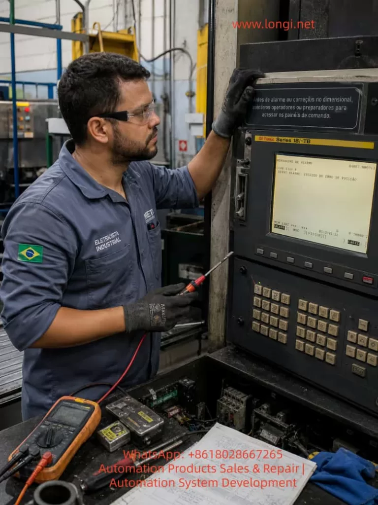
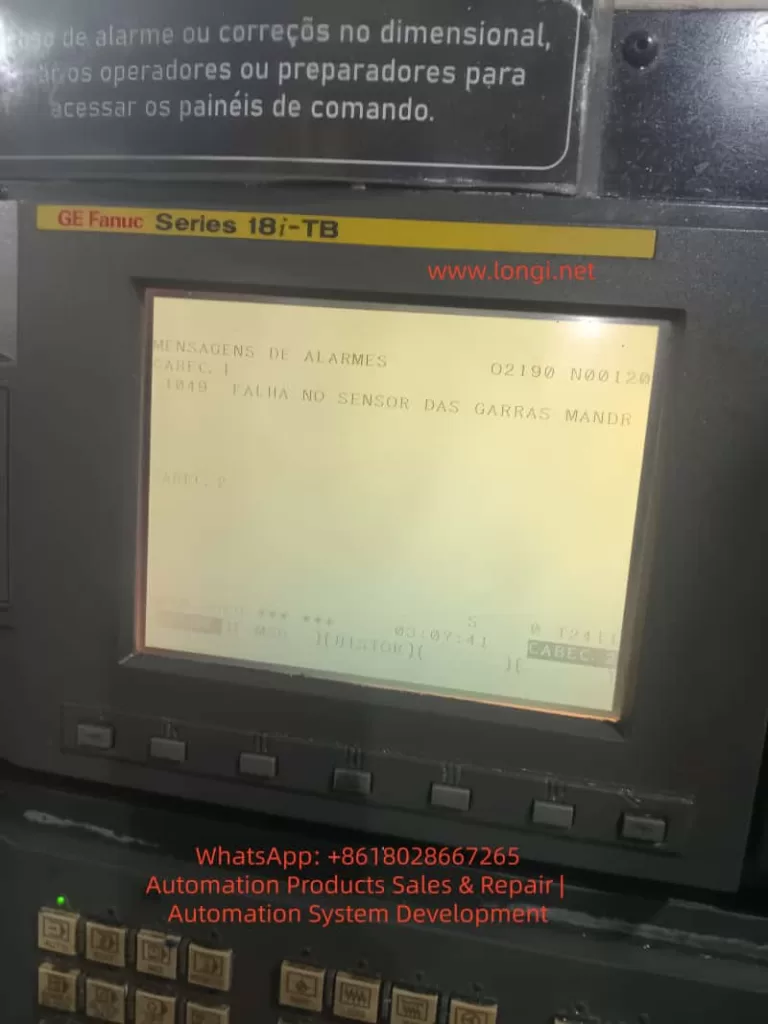
A typical example is a GE Fanuc Series 18i-TB CNC lathe displaying the following Portuguese alarm message:
1049 FALHA NO SENSOR DAS GARRAS MANDR
This can be translated as:
1049: Failure in the chuck jaw sensor
or more specifically:
Abnormal detection of the spindle chuck clamping/unclamping position sensor.
The Portuguese terms can be understood as follows:
FALHA means fault or failure.
SENSOR means sensor.
GARRAS means jaws or clamping jaws.
MANDR is most likely an abbreviation of mandril, meaning chuck, mandrel, or clamping device.
Therefore, this alarm does not primarily indicate a damaged Fanuc CNC main board, servo axis fault, or spindle amplifier failure. The key fault area is the machine-side chuck clamping detection circuit, especially the chuck jaw sensor, hydraulic chuck position detection, and the PMC input logic.
On a CNC lathe, chuck clamping confirmation is a critical safety interlock. If the control cannot confirm that the workpiece is securely clamped, the machine may inhibit spindle rotation, block automatic cycle start, or stop the machine with an alarm. This prevents dangerous situations such as workpiece ejection, chuck accidents, and serious injury.
2. Meaning of the Alarm
The Fanuc 18i-TB is a widely used CNC control for turning machines. It controls axis movement, spindle commands, program execution, operator interface, diagnostics, and CNC functions. However, many auxiliary machine actions are not defined only by the Fanuc CNC software. Functions such as the hydraulic chuck, turret, tailstock, lubrication, door lock, hydraulic unit, coolant pump, chip conveyor, and safety interlocks are usually controlled through the PMC ladder program written by the machine builder.
For this reason, an alarm number such as 1049 is normally a machine-builder custom alarm. The same alarm number may mean different things on different machines, even if both machines use a Fanuc 18i-TB control. In this case, the displayed alarm text clearly states:
FALHA NO SENSOR DAS GARRAS MANDR
This makes the fault direction clear: the problem is related to the sensor for the chuck jaws or chuck clamping device.
This alarm usually means that the PMC ladder is waiting for a specific input signal, but the expected signal is not present. Typical situations include:
- The chuck is commanded to clamp, but the clamp confirmation sensor does not turn ON.
- The chuck is commanded to unclamp, but the unclamp confirmation sensor does not turn ON.
- Both chuck clamp and chuck unclamp signals remain OFF.
- Both chuck clamp and chuck unclamp signals appear ON at the same time.
- The internal/external clamping mode does not match the actual sensor logic.
- The hydraulic cylinder does not reach its end position.
- The sensor is damaged, the cable is broken, the 24 VDC supply is missing, or the PMC input point is defective.
Therefore, troubleshooting should focus on the machine-side chuck mechanism, hydraulic circuit, proximity switches, sensor wiring, and PMC input status, rather than immediately replacing Fanuc CNC boards.
3. Basic Logic of Chuck Position Detection on CNC Lathes
To diagnose this type of alarm correctly, it is necessary to understand how chuck position detection normally works on a hydraulic CNC lathe.
A standard CNC lathe uses a chuck at the front of the spindle. At the rear of the spindle, a hydraulic rotary cylinder drives a drawtube or drawbar. This drawtube moves the internal wedge mechanism of the chuck, causing the jaws to clamp or unclamp the workpiece.
To allow the CNC/PMC to know the chuck condition, the machine builder usually installs position detection sensors near the rear spindle hydraulic cylinder. These sensors detect the position of the drawtube, piston rod, detection ring, or metal target.
A common arrangement includes:
- One proximity switch for chuck clamp confirmation.
- One proximity switch for chuck unclamp confirmation.
- One or more metal targets or sensing blocks.
- A mounting bracket near the hydraulic cylinder or drawtube.
- A signal cable routed back to the machine I/O unit.
In a normal two-sensor configuration, the logic is usually:
| Chuck Status | Clamp Sensor | Unclamp Sensor |
|---|---|---|
| Chuck clamped | ON | OFF |
| Chuck unclamped | OFF | ON |
If the PMC requests chuck clamping but does not receive the clamp sensor signal, it interprets the chuck as not clamped.
If the PMC requests chuck unclamping but does not receive the unclamp sensor signal, it interprets the chuck as not unclamped.
If both signals are ON or both are OFF, the ladder may treat this as an abnormal sensor state.
Some machines also support internal clamping and external clamping modes. In external clamping, the jaws move inward to grip the outside diameter of the workpiece. In internal clamping, the jaws move outward to grip the inside diameter. Because the hydraulic cylinder direction and the definition of “clamped” may be different between these two modes, an incorrect internal/external clamping selection can cause a false chuck sensor alarm.
4. Common Causes of the Alarm
4.1 Proximity Switch Position Shift
This is one of the most common causes. The proximity switches near the spindle rear hydraulic cylinder are exposed to vibration, oil mist, coolant, chips, and mechanical impact. Over time, the sensor bracket may loosen or the sensing gap may change. The sensor may still be electrically good, but it cannot reliably detect the metal target.
Typical symptoms include:
- The chuck can physically clamp and unclamp.
- Hydraulic movement sounds normal.
- The sensor indicator LED sometimes turns ON and sometimes does not.
- The alarm appears intermittently.
- The machine works when cold but alarms after vibration or thermal expansion.
- Slightly moving the sensor or bracket changes the alarm condition.
- The alarm appears more often after maintenance near the spindle rear area.
The solution is to readjust the proximity switch position. The sensing gap should not be set at the maximum detection distance. It should have a safety margin. In many field cases, a gap of approximately 1–2 mm is a reasonable starting point, depending on the sensor model and target material. After adjustment, the technician should repeatedly clamp and unclamp the chuck to confirm stable switching.
4.2 Damaged Proximity Switch
Chuck position sensors work in a harsh environment. They are often exposed to oil contamination, coolant mist, metal chips, and vibration. Over time, the proximity switch or its cable may fail.
Typical signs of a damaged sensor include:
- 24 VDC supply is present, but the output never changes.
- The sensor LED never turns ON.
- The sensor LED remains ON all the time.
- The output voltage is unstable.
- The signal flickers when the sensor body is tapped.
- The cable near the sensor head is cracked or oil-damaged.
- The sensing face is damaged by metal contact.
- The sensor works only when the cable is bent in a certain position.
When replacing the sensor, the technician must not select a replacement only by physical size. The electrical specification must be correct. Important parameters include:
- Supply voltage, usually 24 VDC.
- Output type: NPN or PNP.
- Contact logic: normally open or normally closed.
- Two-wire, three-wire, or four-wire type.
- Sensing distance.
- Thread size, such as M8, M12, or M18.
- Shielded or unshielded construction.
- Cable color and wiring standard.
If an NPN sensor is replaced with a PNP type, or a normally open sensor is replaced with a normally closed type, the sensor may appear to work locally but the PMC logic will be wrong. This can cause the alarm to remain active or create a reverse chuck status indication.
4.3 Insufficient Hydraulic Pressure
A chuck sensor alarm does not always mean the sensor is defective. In many cases, the chuck has not actually reached the required mechanical position. If the hydraulic cylinder does not complete its travel, the sensor will naturally fail to detect the correct position.
Hydraulic-related causes include:
- Hydraulic power unit not running.
- Low hydraulic pressure.
- Low oil level.
- Contaminated hydraulic oil.
- Worn hydraulic pump.
- Pressure relief valve set too low.
- Solenoid valve not shifting.
- Valve spool sticking.
- Internal leakage in the rotary cylinder.
- External oil leakage.
- Faulty pressure switch.
- Blocked filter or restricted oil passage.
If the chuck movement is slow, weak, noisy, or incomplete, the hydraulic system must be checked before adjusting sensors. Adjusting a sensor to compensate for incomplete hydraulic movement is unsafe and unreliable.
Chuck clamping pressure must be appropriate for the workpiece size, material, chuck type, machining load, and spindle speed. Too little pressure may cause workpiece slippage or ejection. Too much pressure may deform thin-wall parts or accelerate chuck wear. The goal is not to set maximum pressure, but to restore the correct pressure range required by the machine and process.
4.4 Mechanical Sticking of the Chuck
The chuck itself can also cause this alarm. Over long-term operation, chips, sludge, dried grease, and coolant residues can accumulate inside the chuck. The jaw guides, wedge mechanism, master jaws, and scroll or wedge surfaces may become tight or uneven.
Typical symptoms include:
- Chuck movement sounds heavy or abnormal.
- Clamp or unclamp speed becomes slow.
- One jaw moves differently from the others.
- The chuck works without a workpiece but alarms when clamping a workpiece.
- The alarm appears after changing to a different workpiece diameter.
- The alarm occurs when the jaw travel is near the end of its range.
- The chuck requires unusually high hydraulic pressure to move.
Maintenance should include:
- Removing the jaws.
- Cleaning jaw grooves and serrations.
- Removing chips and hardened grease.
- Inspecting wedge and sliding surfaces.
- Checking the drawtube connection.
- Lubricating with proper chuck grease.
- Confirming that jaw travel is not at the mechanical limit.
- Checking the rotary cylinder stroke.
If the chuck is badly worn, heavily contaminated, or mechanically damaged, it should be rebuilt or replaced. A chuck is a high-risk rotating clamping device. It should not be forced into operation by bypassing sensors.
4.5 Wiring or Terminal Contact Fault
Sensor wiring problems are also very common on older CNC lathes. Cables near the spindle rear area are exposed to vibration, oil, coolant, and mechanical movement. They may develop intermittent open circuits, insulation failure, connector contamination, or broken conductors inside the cable sheath.
Common wiring faults include:
- Broken sensor power wire.
- Loose 0 V common wire.
- Broken output wire.
- Oil-contaminated connector.
- Loose terminal strip.
- Damaged cable insulation.
- Oxidized relay contact.
- Poor contact at the I/O module connector.
- Incorrect reconnection after maintenance.
The key diagnostic method is to compare the signal at three points:
- The LED indication on the sensor body.
- The voltage change on the sensor output wire.
- The corresponding input bit in the Fanuc PMC diagnosis screen.
If the sensor LED changes normally but the PMC input does not change, the problem is usually between the sensor output and the CNC I/O input. This includes cable, terminals, intermediate connectors, relays, interface boards, or the I/O module.
4.6 Defective PMC Input Point or I/O Module
Although less common than sensor or wiring faults, a defective PMC input point can also cause this alarm. The Fanuc 18i-TB usually receives external machine signals through an I/O unit, I/O Link module, or machine-side interface board. If an input point is defective, the external sensor may output correctly, but the control will not recognize the change.
Diagnostic methods include:
- Measuring the voltage directly at the I/O input terminal.
- Observing the corresponding X input bit in the PMC diagnostic screen.
- Comparing with adjacent input points.
- Temporarily testing the sensor signal on a known good input point.
- Checking I/O module power.
- Checking the common terminal.
- Inspecting the connector between the I/O board and CNC system.
If the input module is confirmed defective, replacement may be required. In some cases, a spare input point can be used, but this requires a correct ladder modification. PMC changes should only be performed by personnel who understand the original ladder logic and have the machine documentation.
4.7 Incorrect Internal/External Clamping Mode
Many CNC lathes allow selection between internal clamping and external clamping. In external clamping, the jaws clamp inward on the outside of the workpiece. In internal clamping, the jaws expand outward into the bore of the workpiece. The hydraulic cylinder movement and the meaning of “clamped” may be reversed depending on the machine design.
If the clamping mode is selected incorrectly, the machine may physically grip the workpiece, but the PMC may judge the sensor state as invalid.
Checks should include:
- Confirming whether the current operation uses internal or external clamping.
- Checking the clamping mode selector switch.
- Confirming jaw installation direction.
- Checking related PMC inputs or keep relays.
- Reading the machine manual for chuck sensor logic.
- Confirming which sensor should be ON after clamping in the selected mode.
This issue is especially common after chuck jaw replacement, soft jaw machining, maintenance work, or operator shift changes.
5. Field Diagnostic Procedure
Step 1: Record the Alarm Message and Operating Condition
The technician should first record the exact alarm number, alarm text, machine mode, and the moment when the alarm occurs. In this case, the alarm message points directly to the chuck jaw sensor, so the alarm should be treated as a machine-side PMC alarm.
Important questions include:
- Does the alarm appear immediately after power-on?
- Does it appear when clamping the chuck?
- Does it appear when unclamping the chuck?
- Does it appear when starting the spindle?
- Does it appear when starting automatic cycle?
- Does it appear during machining?
- Did it start after maintenance?
- Did it start after changing jaws or workpiece size?
The timing of the alarm provides a strong clue. If it appears during clamping, focus on the clamp confirmation signal. If it appears during unclamping, focus on the unclamp confirmation signal. If it appears only when starting the spindle, focus on the chuck clamp safety interlock.
Step 2: Manually Operate the Chuck
The next step is to operate the chuck manually and observe actual mechanical movement. The technician should not rely only on the screen or solenoid valve sound. The physical movement of the chuck jaws and rear hydraulic cylinder must be confirmed.
Check the following:
- Does the chuck clamp?
- Does the chuck unclamp?
- Do the jaws move smoothly?
- Is there a delay?
- Does the hydraulic cylinder move fully?
- Does the hydraulic pressure change?
- Is the workpiece held securely?
- Does the movement reach the end position?
If the chuck does not move at all, troubleshooting should shift toward the hydraulic power unit, solenoid valve, foot switch, interlock conditions, and control circuit.
If the chuck moves normally but the alarm remains, the focus should shift to sensors and input signals.
Step 3: Check the Hydraulic Unit and Pressure
Hydraulic pressure is essential for reliable chuck operation. If the pressure is too low, the sensor alarm may be a consequence rather than the root cause.
Check:
- Whether the hydraulic motor is running.
- Oil level.
- Oil temperature.
- Hydraulic pressure gauge reading.
- Chuck clamping pressure setting.
- Solenoid valve coil status.
- Valve shifting action.
- Oil leakage.
- Rotary cylinder internal leakage.
- Filter blockage.
If hydraulic pressure is abnormal, the hydraulic system must be repaired first. Only after the chuck movement is mechanically correct should the sensor circuit be judged.
Step 4: Inspect the Sensors at the Rear of the Spindle
Open the rear spindle cover and locate the proximity switches near the chuck hydraulic cylinder. Usually there are two sensors: one for clamp confirmation and one for unclamp confirmation.
Observe the sensor LEDs while operating the chuck:
- When clamped, the clamp sensor should turn ON.
- When unclamped, the unclamp sensor should turn ON.
- The two sensors should switch alternately.
- They should not both remain ON.
- They should not both remain OFF.
If the LED does not turn ON, check for 24 VDC supply.
If supply is normal but the LED does not change, adjust the sensing distance.
If adjustment does not help, replace the sensor.
If the LED changes correctly but the alarm remains, continue with PMC input diagnosis.
Step 5: Check Fanuc PMC Diagnostic Inputs
One of the most reliable ways to troubleshoot this problem is to inspect the PMC input status directly.
On many Fanuc 18i-TB controls, the general path is:
- Press SYSTEM.
- Enter PMC.
- Select PMCDGN or PMC Diagnosis.
- Display the relevant X input address.
- Clamp and unclamp the chuck.
- Observe whether the corresponding input bit changes.
The exact soft key names may vary depending on the machine configuration. The machine electrical drawings should identify the I/O address for chuck clamp confirmation, chuck unclamp confirmation, clamping mode, pressure switch, and related safety interlocks.
If the electrical drawings are unavailable, an experienced technician may observe the X input area while operating the chuck and identify the changing bits. This method must be used carefully because multiple signals may change at the same time.
Step 6: Measure the Sensor Output Signal
When the sensor LED and PMC input do not agree, use a multimeter to measure the signal path.
Measure at:
- Sensor power terminal.
- Sensor output wire.
- Intermediate junction box.
- Terminal strip.
- I/O module input terminal.
- 0 V common terminal.
For a common three-wire PNP proximity sensor:
- Brown is usually +24 V.
- Blue is usually 0 V.
- Black is usually output.
When a PNP sensor is active, the black output wire usually switches close to +24 V.
For an NPN sensor, the output is usually pulled toward 0 V when active.
The actual wiring must always be confirmed against the machine circuit diagram.
6. Repair Methods
6.1 Adjust the Sensor Position
If the sensor is electrically good but does not detect reliably, adjust its position.
Procedure:
- Clean the sensor face and metal target.
- Loosen the sensor mounting nut.
- Adjust the sensing gap.
- Watch the LED switching point.
- Avoid setting the sensor at the edge of detection.
- Tighten the mounting nut.
- Test repeated clamp/unclamp cycles.
- Confirm stable PMC input switching.
After adjustment, test under realistic operating conditions. Vibration during spindle operation should not cause signal flicker. If vibration affects the signal, reinforce the bracket or replace the sensor with a more suitable type.
6.2 Replace the Proximity Switch
If the sensor is defective, replace it with a compatible model.
After replacement, verify:
- 24 VDC supply.
- Correct LED operation.
- Correct output voltage.
- Correct PMC input status.
- Correct clamp/unclamp logic.
- Alarm reset.
- Spindle start interlock operation.
The repair is not complete just because the sensor LED turns ON. The CNC/PMC must also read the signal correctly.
6.3 Repair Cable and Terminal Problems
If the sensor output is normal but the PMC input does not change, repair the signal path.
Possible actions include:
- Tightening terminal screws.
- Cleaning oil-contaminated connectors.
- Replacing damaged cables.
- Repairing aviation plugs.
- Checking wire numbers against drawings.
- Checking the 0 V common line.
- Inspecting I/O module connectors.
- Re-routing cables away from moving parts.
Cable routing around the spindle rear area must be secure. The cable should not rub against rotating parts or sharp edges.
6.4 Repair the Hydraulic System
If the chuck does not reach its position, repair the hydraulic system.
Typical work includes:
- Refilling hydraulic oil.
- Replacing contaminated oil.
- Cleaning or replacing filters.
- Adjusting chuck pressure.
- Checking the hydraulic pump.
- Checking solenoid valves.
- Cleaning valve spools.
- Inspecting the rotary cylinder seals.
- Repairing oil leaks.
After hydraulic repair, chuck clamping force must be verified. A machine that no longer alarms but has weak chuck force is still unsafe.
6.5 Clean and Service the Chuck
If mechanical sticking is found, service the chuck.
Recommended work includes:
- Removing jaws.
- Cleaning jaw slots.
- Cleaning serrations.
- Removing chips and hardened grease.
- Inspecting wedge and sliding surfaces.
- Lubricating with correct chuck grease.
- Checking drawtube connection.
- Confirming full jaw stroke.
- Checking the rotary cylinder stroke.
A worn or damaged chuck should be professionally rebuilt or replaced. Bypassing sensors to continue using a faulty chuck is unsafe.
7. Safety Precautions
A chuck sensor alarm must not be permanently bypassed. Some technicians may short the clamp confirmation signal to allow the machine to run temporarily. This practice is dangerous.
The chuck clamp confirmation signal may participate in:
- Spindle start permission.
- Automatic cycle start permission.
- Hydraulic clamp confirmation.
- Door safety logic.
- Tailstock interlock.
- Robot or bar feeder interlock.
- Loader/unloader safety sequence.
If the signal is bypassed, the spindle may start even when the workpiece is not properly clamped. At high speed, this may result in workpiece ejection, machine damage, and serious injury.
Temporary signal simulation is acceptable only for controlled diagnosis by qualified personnel, and only under strict conditions:
- Spindle disabled.
- Workpiece removed.
- Speed command set to zero.
- Personnel away from the danger zone.
- Original wiring restored immediately after testing.
A proper repair must restore real and stable chuck position detection.
8. Case Summary
For the GE Fanuc Series 18i-TB CNC lathe displaying:
1049 FALHA NO SENSOR DAS GARRAS MANDR
the most reasonable diagnosis is:
The chuck jaw sensor or chuck clamping/unclamping detection signal is abnormal. The PMC does not receive the correct chuck status confirmation signal.
The most likely fault points are:
- Misadjusted clamp/unclamp proximity switch near the rear spindle hydraulic cylinder.
- Defective proximity switch.
- Broken or loose sensor cable.
- Low hydraulic pressure causing incomplete chuck movement.
- Mechanical sticking in the chuck.
- Incorrect internal/external clamping mode.
- Defective PMC input or I/O module.
The recommended troubleshooting sequence is:
- Manually operate the chuck and confirm mechanical movement.
- Check hydraulic pressure.
- Inspect the clamp/unclamp sensor LEDs.
- Adjust sensor position.
- Measure sensor power and output.
- Check the related X input in the Fanuc PMC diagnosis screen.
- Inspect cable, terminals, and I/O module.
- Repair hydraulic or mechanical problems if movement is incomplete.
- After alarm reset, test chuck operation and spindle interlock repeatedly.
9. Post-Repair Verification
After repair, the technician should not judge success only by the disappearance of the alarm. A complete functional test is necessary.
Recommended verification includes:
- Clamp/unclamp test without workpiece.
- Clamp test with workpiece.
- Test with different jaw positions if applicable.
- Low-speed spindle start test.
- Medium-speed spindle running test.
- Emergency stop and recovery test.
- Automatic cycle start test.
- Internal/external clamping mode check.
- Repeated clamp/unclamp cycles.
- PMC input stability confirmation.
The machine should be returned to production only when chuck movement is reliable, sensor signals are stable, hydraulic pressure is normal, and spindle safety interlocks function correctly.
10. Conclusion
When a Fanuc 18i-TB CNC lathe displays 1049 FALHA NO SENSOR DAS GARRAS MANDR, the fault is usually related to the chuck jaw sensor or chuck clamp/unclamp detection circuit. This is a typical machine-side PMC custom alarm, not a direct indication of Fanuc CNC board failure, servo drive failure, or parameter loss.
The correct diagnostic approach is to follow the chuck clamping chain step by step: hydraulic movement, mechanical travel, proximity switches, sensor wiring, and PMC input status. In field repair, the most common causes are misadjusted or damaged clamp/unclamp proximity switches near the rear spindle hydraulic cylinder, followed by low hydraulic pressure, mechanical chuck sticking, and wiring contact faults.
Chuck clamping detection is a critical safety function on CNC lathes. It must not be permanently bypassed, shorted, or disabled. A safe and reliable repair must restore true chuck status detection so that the CNC can correctly confirm clamping before allowing spindle rotation and automatic machining.