
1. Introduction
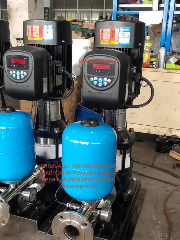
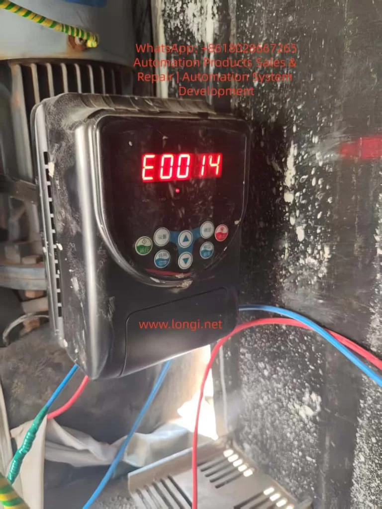
In the realm of industrial automation, the Variable Frequency Drive (VFD) serves as the “heart” of the motor drive system, undertaking core functions such as speed regulation, energy saving, and overload protection. The Weier (Weier) S320 series inverters, known for their high cost-performance ratio and stable vector control performance, are widely applied in constant pressure water supply, fans, pumps, conveyors, and packaging machinery. They cover a power range from 0.75kW to 37kW. However, during long-term operation, inverters inevitably encounter various faults. Among these, E0014 “Output Side Phase Loss (or Severe Load Three-Phase Imbalance)” is one of the most common fault codes in the S320 series.
If the E0014 fault is not addressed promptly, it can lead to motor burnout, equipment downtime, and even safety accidents. According to statistics from an industrial maintenance platform, E0014 accounts for approximately 18% of faults in S320 series inverters. Of these, 60% stem from wiring issues, 25% from motor or cable faults, 10% from inverter hardware damage, and 5% from load or parameter issues. This article provides a comprehensive analysis of the E0014 fault from the perspectives of fault principles, cause analysis, systematic troubleshooting processes, typical cases, and prevention strategies, offering a practical solution guide for engineers and technicians.
2. Definition and Detection Principle of E0014 Fault
2.1 Official Definition of Fault Code
According to the Weier S320 Series Inverter User Manual, the accurate description of the E0014 fault is:
Output Side Phase Loss (or Severe Load Three-Phase Imbalance): The inverter detects that one or two phases of the three phases (U, V, W) at the output terminal have no current output, or the imbalance of three-phase current (voltage) exceeds the set threshold.
2.2 Detection Principle: Current Sampling and Threshold Judgment
The S320 series inverter employs a detection mechanism based on Current Sensors (Hall Sensors) + Digital Signal Processing (DSP). The core logic is as follows:
- Current Sampling: Three-phase Hall sensors installed near the output terminals collect the output current of the U, V, and W phases in real-time (sampling frequency is approximately 10kHz).
- Imbalance Calculation: The DSP chip calculates the imbalance of the three-phase current using the following formula:
Imbalance=Average CurrentMax Current−Min Current×100%
- Threshold Trigger: When the imbalance exceeds the default value of 20% (adjustable via parameter F012), or when the current of a certain phase is zero (phase loss), the inverter immediately locks the IGBT drive signal, stops output, and displays E0014 on the panel.
Note: “Severe load three-phase imbalance” is also a triggering condition. For example, if a fan blade breaks or a pump impeller jams, the motor’s three-phase load becomes unbalanced, causing the three-phase current deviation to exceed the threshold. Even if the wiring and motor are intact, this will trigger E0014.
3. Core Cause Analysis of E0014 Fault
The essence of the E0014 fault is a severe imbalance in three-phase current (voltage) on the output side. The causes can be divided into four categories: Wiring Issues, Motor & Cable Faults, Inverter Hardware Damage, and Load Abnormalities.
3.1 Wiring Issues: The Most Common “Explicit Fault”
Wiring is the “energy transmission channel” between the inverter and the motor. Its reliability directly affects the current balance on the output side. Common problems include:
- Loose Terminals: Vibration or oxidation causes poor contact at the inverter output terminals (U, V, W) or motor terminal box terminals. Contact resistance increases (e.g., from 0.1Ω to 10Ω) or even disconnects completely. For instance, in a constant pressure water supply system, a loose V-phase terminal due to long-term vibration caused the phase current to drop from 15A to 0A, triggering E0014.
- Wire Breakage: Mechanical damage (e.g., crushed by heavy objects) or aging (insulation cracking leading to core wire breakage) causes a phase wire to disconnect. For example, the output cable of a conveyor equipment broke at the terminal due to frequent movement, resulting in no W-phase output.
- Wiring Errors: Although rare, reversing the U, V, W phase sequence or failing to connect a phase (e.g., connecting only two phases) will cause output phase loss. However, wiring errors more often cause the motor to reverse or fail to start rather than directly triggering E0014, but they must be checked.
3.2 Motor and Cable Faults: The “Hidden Danger” Zone
The motor is the load of the inverter. The condition of its windings and the insulation performance of the cable directly affect the current balance. Common issues include:
- Motor Winding Burnout: Long-term phase-loss operation (e.g., power supply side phase loss), overload, or poor heat dissipation causes winding insulation to age and eventually burn out a phase winding. For example, a pump motor’s U-phase winding burned out due to bearing wear causing overload. The resistance increased from 2.5Ω to infinity, and the inverter detected no current in that phase, triggering E0014.
- Cable Insulation Damage: Aging, moisture, or corrosion causes the insulation layer to crack, leading to short circuits between phases or between phase and ground, resulting in abnormal current in a phase. For example, an outdoor fan cable exposed to rain developed cracked insulation, causing a short between V-phase and ground. The V-phase current surged from 10A to 30A, and the three-phase imbalance exceeded 20%.
- Loose Motor Terminal Box: Vibration causes terminals inside the motor terminal box to loosen, leading to poor contact in a phase wire, similar to the inverter output terminal issue.
3.3 Inverter Hardware Faults: “Fatal Damage” to Core Components
The inverter’s output module (IGBT) and current sensors are key components for detecting output status. Their damage directly causes E0014:
- IGBT Module Damage: The IGBT (Insulated Gate Bipolar Transistor) is the power switching device. If an IGBT in a phase is damaged (open or short circuit) due to overcurrent, overheating, or voltage surge (e.g., lightning strike), there will be no output voltage in that phase, and the motor will have no current. For example, the W-phase IGBT of a fan inverter failed due to a cooling fan malfunction causing overheating. The Collector (C) to Emitter (E) opened, resulting in no W-phase output and triggering E0014.
- Current Sensor Fault: Current sensors (e.g., Hall sensors) detect three-phase output current. If dust accumulation or aging wires cause the sensor output signal to drift (e.g., U-phase sensor output drops from 2.5V to 0V), the inverter will falsely judge that there is no current in that phase and trigger E0014.
- Control Board Fault: Damage to components like A/D converters or operational amplifiers on the control board causes errors in current sampling signal processing, leading to a false phase-loss judgment. However, the probability of control board failure is low (about 5%) and is usually considered only after other causes are ruled out.
3.4 Load Abnormalities: The “Indirect Trigger” Often Overlooked
The three-phase balance of the load directly affects the current distribution of the motor. If the load has abnormalities like jamming or component damage, it causes three-phase load imbalance, leading to severe deviation in three-phase current:
- Fan Blade Damage: A fan blade breaks due to foreign object impact, causing the impeller to rotate with unbalanced three-phase load. The current in one phase increases significantly (e.g., from 10A to 20A), exceeding the imbalance threshold.
- Pump Impeller Jamming: Debris enters the pump, jamming the impeller. The motor needs to output more torque, causing overcurrent in one phase (e.g., from 15A to 30A) and triggering E0014.
- Conveyor Belt Deviation: A deviated conveyor belt causes uneven force on the rollers, leading to unbalanced three-phase motor load and triggering E0014.
- Note: E0014 caused by load abnormalities is usually accompanied by other fault codes (such as Overcurrent E0002) and requires combined judgment.
3.5 Parameter Setting Issues: The “Human Factor” for False Alarms
The phase-loss protection threshold of the inverter (e.g., current imbalance) can be adjusted via parameters. If the threshold is set too sensitive (e.g., less than 10%), even slight three-phase imbalance will trigger E0014. If set too insensitive (e.g., greater than 30%), it fails to provide timely protection, leading to motor burnout. For example, a user adjusted the “Output Phase Loss Detection Threshold” (Parameter F012) from the default 20% to 10%, causing false alarms during normal motor operation due to slight imbalance.
4. Systematic Troubleshooting Process for E0014 Fault
Troubleshooting E0014 must follow the principle of “Safety First, Easy to Difficult, External to Internal”. The specific process is as follows:
4.1 Step 1: Safety Preparation (Avoid Electric Shock Risk)
The DC bus (between P and N terminals) of the inverter stores high-voltage energy (with 380V input, DC bus voltage is approximately 537V). Even after power-off, the capacitor needs 5-10 minutes to discharge. Therefore, before troubleshooting:
- Cut off the inverter’s input power (R, S, T terminals) and hang a “Do Not Energize” warning sign.
- Use a multimeter to measure the DC bus voltage (between P and N terminals) to confirm it is below 36V (safe voltage) before proceeding.
- Wear insulated gloves and use insulated tools (e.g., screwdrivers, clamp meters) to avoid direct contact with live parts.
4.2 Step 2: Output Wiring Inspection (Priority Check)
Wiring issues are the most common cause of E0014 (60%), so check this first:
- Visual Inspection: Open the inverter output terminal cover (U, V, W) and check if wires are loose, broken, or if the insulation is damaged. If loose, tighten the terminals with a torque wrench (refer to the manual for torque values, e.g., 1.2N·m for M4 terminals). If wires are broken, replace them with new wires of the same specification (copper core cable).
- Resistance Measurement: Use the multimeter’s low resistance range (200Ω) to measure the resistance between output terminals (U-V, V-W, W-U). Under normal conditions, the resistance should equal the DC resistance of the motor windings (e.g., 2-3Ω for a 7.5kW motor), and the difference between the three phases should not exceed 5%. If the resistance between two phases is infinite, the wire in that phase is broken. If the resistance difference is too large (e.g., U-V is 2Ω, V-W is 5Ω), it indicates poor contact.
- Insulation Measurement: Use a Megger (Insulation Resistance Tester) to measure the insulation resistance of the output terminals to ground (PE terminal). It should normally be greater than 1MΩ (for low-voltage motors). If the insulation resistance is below 0.5MΩ, the cable insulation is damaged and needs replacement.
4.3 Step 3: Motor and Cable Testing
If the wiring is fine, check the motor and cable:
- Motor Winding Resistance Measurement: Open the motor terminal box and use a multimeter to measure the resistance of U-V, V-W, and W-U. If the resistance of a phase is infinite, the winding is broken. If the resistance difference exceeds 5%, it indicates a short circuit or poor contact in the winding.
- Motor Insulation Resistance Measurement: Use a Megger to measure the insulation resistance of the motor windings to ground (motor casing). It should normally be greater than 1MΩ. If it is below 0.5MΩ, the motor windings are damp or the insulation is aged. It needs to be baked (heat in an oven to 80°C for 4 hours) or the motor needs replacement.
- Cable Continuity Test: Use a multimeter to test the continuity of the cable at both ends (inverter side and motor side). If a phase wire is not conducting, the cable is broken. If there is continuity between phases, the cable is shorted.
4.4 Step 4: Inverter Hardware Diagnosis
If the motor and cable are fine, check the inverter itself:
- IGBT Module Detection: Open the inverter and locate the output IGBT module (usually a three-phase bridge structure, one IGBT per phase, model such as FS150R12KT3). Use the multimeter’s diode range to measure the resistance between the Collector (C) and Emitter (E) of the IGBT:
- Normally, the resistance between C-E is infinite when the IGBT is off. When conducting (red probe on E, black probe on C), the resistance is about 0.5-1Ω (due to the internal freewheeling diode).
- If the C-E resistance of a phase is infinite, the IGBT is open (damaged). If the resistance is very small (close to 0Ω), the IGBT is shorted (damaged).
- Current Sensor Detection: Locate the current sensors (usually near the output terminals, three sensors for three phases). Measure their output voltage with a multimeter (temporary power-on required, be careful). Normally, the sensor output voltage is proportional to the current (e.g., 0-5V corresponds to 0-rated current). If the output voltage of a phase is zero or abnormal (e.g., U-phase outputs 0V while V and W phases output 2.5V), the sensor is damaged.
- Control Board Check: Inspect the control board for signs of burning or bulging capacitors. Use an oscilloscope to measure the current sampling signal (e.g., the signal from the sensor to the control board) to see if it is normal (e.g., sine wave or PWM wave). If the signal is abnormal, replace the control board.
4.5 Step 5: Load Status Verification
If all the above steps show no issues, check the load:
- Manual Rotation: Disconnect the motor from the load (e.g., remove the conveyor chain) and turn the motor shaft by hand to check if it rotates flexibly. If the load is jammed, repair the load (e.g., clean debris from the pump, adjust fan blades).
- Three-Phase Balance Detection: Use a clamp meter to measure the three-phase current of the motor during operation (temporary power-on required, be careful). If the difference between the three-phase currents exceeds 20%, it indicates unbalanced three-phase load. Adjust the load (e.g., replace damaged fan blades, calibrate the pump impeller).
4.6 Step 6: Parameter and Waveform Analysis
If both hardware and load are fine, check parameters and waveforms:
- Parameter Check: Enter the inverter’s parameter setting interface (password required, e.g., default “0000” for S320 series) and check if the “Output Phase Loss Detection Threshold” (Parameter F012) is set reasonably. The default is 20%. If set too low (e.g., 10%), increase it to 20%-25%. If set too high (e.g., 30%), decrease it to 15%-20% (to avoid false alarms).
- Waveform Detection: Use an oscilloscope to measure the voltage waveform at the inverter output terminals (between U, V, W). Normally, it should display a three-phase PWM wave (Pulse Width Modulation wave) with an amplitude equal to the DC bus voltage (approx. 537V) and a frequency equal to the set frequency (e.g., 50Hz). If there is no waveform in a phase, the IGBT in that phase is damaged. If the waveform is distorted (e.g., uneven amplitude), the IGBT drive circuit is faulty.
5. Analysis of Typical Fault Cases
Case 1: Phase Loss Fault Caused by Loose Output Terminal
Scenario: A residential constant pressure water supply system uses a Weier S320-11kW inverter to drive two water pumps (one in use, one on standby). One day, the inverter suddenly reported E0014, and the pump stopped, causing a water outage in the community.
Troubleshooting:
- After shutdown and power-off, the output terminal cover was opened after discharging. The V-phase terminal wire was found to be loose, with obvious oxidation marks between the wire and the terminal.
- A multimeter measured the resistance between U-V and V-W. The resistance between V-W was infinite (normal should be 2.5Ω), indicating a broken V-phase wire.
- The V-phase terminal was retightened, and the oxidized end of the wire was polished with sandpaper. The resistance was measured again, and all three phases showed 2.5Ω, balanced.
- After power-on testing, the inverter operated normally, and the E0014 fault disappeared.
Root Cause: Loose terminal caused poor contact, which worsened due to oxidation over time, eventually leading to disconnection and phase loss.
Solution: Replace the wire end (crimp with a cold-pressed terminal) and inspect terminal tightness weekly.
Case 2: E0014 Triggered by Motor Winding Burnout
Scenario: A factory conveyor using a Weier S320-7.5kW inverter suddenly reported E0014 during operation. The motor stopped, and materials piled up on the conveyor.
Troubleshooting:
- After power-off, the motor terminal box was opened, and the U-phase winding wire was found to be burnt out with charred insulation.
- A multimeter measured the motor winding resistance. The resistance between U-V was infinite, while V-W and W-U were 3Ω (normal), indicating a burnt-out U-phase winding.
- The motor bearings were inspected and found to be severely worn (radial clearance exceeded 0.2mm), causing the motor rotor to rub against the stator, overheating and burning out the winding.
- The motor (same model 7.5kW) and bearings (model 6204) were replaced. After rewiring and power-on, the inverter operated normally.
Root Cause: Bearing wear caused motor overload, overheating the winding until it burned out, resulting in phase loss.
Solution: Inspect motor bearings quarterly (add lubricant) and avoid overload operation (keep conveyor load below 80% of rated value).
Case 3: Output Phase Loss Caused by IGBT Module Damage
Scenario: A workshop fan using a Weier S320-15kW inverter reported E0014 during operation. The fan stopped, and the workshop temperature rose.
Troubleshooting:
- After power-off and discharging, the inverter was opened, and burn marks were found on the Collector and Emitter of the W-phase IGBT module (FS150R12KT3).
- A multimeter measured the C-E resistance of the IGBT. The W-phase was 0Ω (shorted), while U and V phases were infinite (normal).
- The cooling fan was inspected and found not rotating (bearing seized