
Introduction
In the field of industrial automation, the Siemens SIMOVERT Masterdrives VC series inverters are widely used in high-performance drive applications such as machine tools, hoisting, and metallurgy due to their Vector Control technology and high reliability. This series adopts a modular design, where the CUVC (Control Unit Vector Control) serves as the core “brain,” responsible for parameter configuration, closed-loop control, and fault diagnosis. However, during actual maintenance, a common issue arises after replacing the CUVC: the P071 “Line Volts” parameter cannot be set according to the old configuration.
Based on a typical case study, this article systematically analyzes the root cause of the fault and the parameter dependency mechanism. It provides a complete, reproducible on-site programming solution to help engineers quickly restore equipment operation.
The P071 parameter in Masterdrives VC is not isolated; it directly affects DC link voltage calculation, pre-charge monitoring, undervoltage protection (F008), and the Vdmax controller (P515). Incorrect configuration can lead to the drive failing to power up, frequent tripping, or even hardware damage. Combining official manuals, the DriveMon software interface, and nameplate data, this article details the correct operation process—from power section definition to full motor parameterization—ensuring readers grasp the essential technical points for a permanent fix.
Overview of the Masterdrives VC System and CUVC Unit
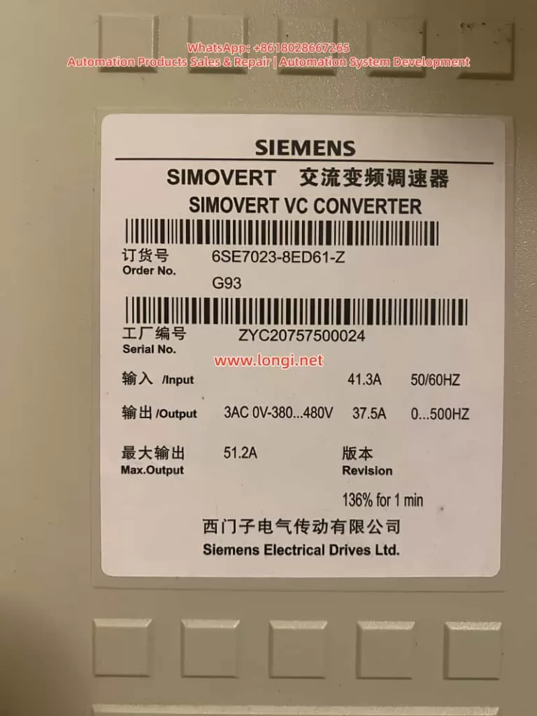
The SIMOVERT Masterdrives VC (e.g., Order No. 6SE7023-8ED61-Z) is a Compact Unit in the 380~480V AC input voltage class. Typical nameplate data includes:
- Input: 41.3A, 50/60Hz
- Output: 3AC 0~380…480V, 37.5A, 0…500Hz
- Max Output: 51.2A (136% for 1 minute)
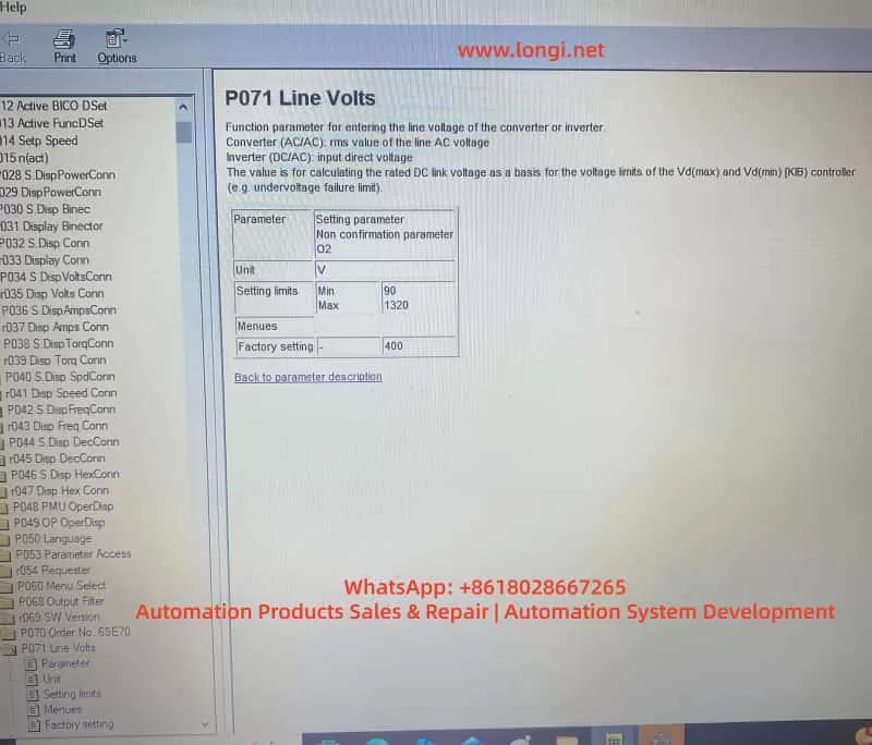
The CUVC control unit locks the power section type (Device Type) via parameter P070 (Order No. / MLFB), which in turn determines the minimum/maximum setting range for P071. The functions of P071 are:
- AC/AC Mode: Input line voltage effective value (RMS).
- DC/AC Inverter Mode: DC link voltage.
- Used to calculate the rated DC link voltage, serving as the reference for Vd(max)/Vd(min) controllers and undervoltage fault limits.
Official manuals explicitly state that P071 must match the hardware voltage class. For 380~480V hardware, the factory default for P071 is approximately 400V, and the minimum value is typically restricted to around 208V; it cannot be arbitrarily set to 90V. Only low-voltage hardware (e.g., 200~230V) allows lower limits. This is the core reason why the “old card could be set to 90V, but the new card only recognizes 400V” after replacement.
DriveMon software (or PMU/OP1S) is the primary tool for parameterization, offering wizard menus such as “Power Section Definition” and “Drive Setting.” Correctly operating these menus prevents parameter conflicts.
Typical Fault Case Description
At a site, the original Masterdrives VC drive (6SE7023-8ED61-Z) was running normally. The old CUVC card had P071 set to 90V, with motor parameters rated at 230V, 37.5A, linear U/f characteristics, sensorless mode, and a ramp time of 10s. After replacing the CUVC with a new one and powering up via DriveMon, the following was observed:
- In the Device Identification interface, after selecting the correct MLFB from the device list, the minimum value for P071 was locked to a higher range (approx. 400V).
- Attempting to modify P071 to 90V resulted in the software rejecting the save or automatically reverting to the default value.
- Other parameters, such as P100 (control mode), P101~P108 (motor data), ramp generators (P462/P464), and U/f characteristics (P330, etc.), needed to be re-entered; otherwise, the drive would not run.
If a low-voltage configuration is forced, the system will report an F008 undervoltage fault, a pre-charge timeout (pre-charge needs to reach P071 × 1.34 × 80%), or even damage the pre-charge circuit. The DriveMon screenshots provided by the user (P071 parameter page, motor configuration page, sensorless page, ramp page, U/f page) clearly showed the default state of the new card versus the “mismatch” of the old card.
Root Cause Analysis: Hardware Dependency Mechanism of P071
The root cause of the fault lies in the “binding” relationship between the CUVC and the power section:
- P070 MLFB Definition: After power-up, the CUVC must have the correct code entered via P060=8 (Power Section Definition menu) (corresponding to 6SE7023-8ED61-Z). The old card might have incorrectly selected a low-voltage MLFB (low P070 value), causing the P071 limit to be relaxed to 90V. The new card restores the correct MLFB, and the limit automatically tightens.
- Voltage Class Protection: The manual specifies that P071 is used to calculate the rated DC link voltage (P071 × 1.34). For 380~480V hardware, the normal DC link range is 510~810V. An input of 90V would cause the pre-charge circuit to fail to reach the threshold, triggering protection.
- Parameter Linkage: P071 affects P072 (rated current), P078 (frequency), P515 (Vdmax control), etc. The “Device Type” dropdown list in DriveMon directly determines these limits.
- Software Version and Firmware: Different CUVC firmware versions have stricter checks on P071. The new card might be a newer version that enforces hardware matching more strictly.
Additionally, the mismatch between the motor’s 230V nameplate and the drive’s 380~480V hardware may stem from Star/Delta wiring or a step-down application, but P071 must reflect the actual input supply voltage, not the motor voltage.
Complete Solution: Full Process from CUVC Replacement to Parameter Restoration
Preparation
- Power off the drive and confirm the actual input voltage (measure line voltage with a multimeter).
- Install DriveMon software and connect to the CUVC (X300 serial port).
- Back up parameters from the old card (if still connectable): DriveMon → Save to PC.
- Before powering up the new CUVC, ensure P053=6 (Parameter access enable).
Step 1: Power Section Definition (Core to solving P071 restrictions)
- Enter DriveMon → Device Identification / Configuration menu.
- In the device list, precisely select 6SE7023-8ED61-Z (displaying AC 380-480V or DC 510-810V).
- Click Next to confirm. The system will automatically update P070 MLFB and the P071/P072 limits.
- Return to the parameter menu to verify that P071 can now be modified normally (but still cannot be set to 90V).
Step 2: Set P071 Line Volts
- Enter the P071 parameter page.
- Enter the actual measured input voltage (recommended 380~400V).
- AC/AC Mode: Line voltage RMS value.
- DC/AC Mode: DC link voltage.
- Save and exit. P071 will no longer allow 90V because the hardware does not support it.
Step 3: Complete Parameter Entry (Corresponding to user-provided screenshots)
Use the “Drive Setting” menu (P060=5) in DriveMon or set parameters individually:
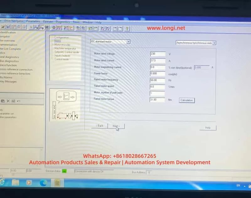
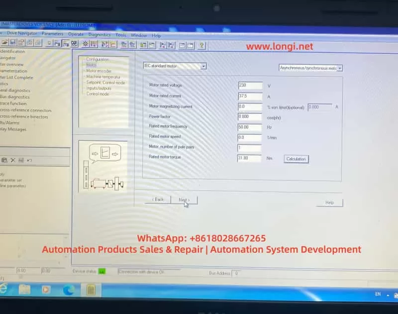
- Motor Parameters (Corresponding to Screenshot 4):
- P095=10 (IEC Asynchronous/Synchronous motor)
- P101=230V (Motor rated voltage)
- P102=37.5A (Motor rated current)
- P104=0.800 (Power factor cosφ)
- P106=50.00Hz (Rated frequency)
- P107=0.0 1/min (Rated speed, per nameplate or 0)
- P108=1 (Pole pairs)
- P109=31.80 Nm (Rated torque)
- Click “Calculation” to automatically calculate magnetizing current, etc.
- Motor Sensor (Screenshot 5):
- Select “No motor sensor” (Sensorless mode).
- Setpoints and Ramps (Screenshots 6, 7):
- ON/OFF1 activation.
- Motor potentiometer mode.
- Acceleration time P462=10.0s, upper limit 100%.
- Deceleration time P464=10.0s, lower limit 0%.
- Ramp function generator with limits.
- U/f Characteristics (Screenshots 8, 9):
- Select “Linear”.
- Slip compensation = 0.0%.
- Protection ramp Kp (below 15% frequency) = 1.0.
- Minimum frequency = 0.0%.
- Skip frequency = 0.0%.
- Keep others like Udm ax closed loop, rotating motor catch, etc., OFF or at default.
Step 4: Drive Start-up and Optimization
- P052=5 (Drive Setting).
- P052=7 (Motor identification at standstill), press P to start (A078 alarm, close the breaker within 20 seconds).
- Save parameters: P053=6 → P060=2 → P970=0 (Reset to take effect).
- Power on and test Diagnostics → Faults/Alarms to confirm no F008, etc.
- If you have a backup of the old card, download the full parameter set directly.
The entire process usually takes 30~60 minutes. The new CUVC will then restore the same operating characteristics as the old card.
Best Practices and Safety Precautions
- Always define the power section first: After replacing the CUVC, executing P060=8 is mandatory; otherwise, the risk is extremely high.
- Voltage matching principle: P071 must equal the actual supply voltage. Setting it below the hardware minimum is strictly prohibited.
- Accuracy of motor data: Use nameplate data. Perform static/dynamic identification if necessary.
- Backup and version management: Back up parameters before every maintenance and record the CUVC firmware version.
- Fault diagnosis: Common accompanying faults include F008 (Undervoltage) and A078 (Identification alarm). Refer to the manual’s “Fault and Alarm Messages” chapter.
- EMC and Safety: Power off the drive when setting parameters. Follow grounding and shielding requirements on-site.
- Advice for low-voltage applications: If the site truly requires 90V power supply, replace the hardware with a matching 200~230V class unit rather than trying to “cheat” the software.
Extended Troubleshooting for Similar Faults
- P071 is always grayed out? → Check P053 parameter access rights or P060 menu selection.
- Restrictions remain after selecting MLFB? → Confirm that the DriveMon database matches the CUVC firmware. Update the software if necessary.
- Motor does not turn / Torque is insufficient? → Re-check P100 control mode, P330 U/f curve, and P462/P464 ramp times.
- Multi-drive parallel or regenerative braking scenarios? → Pay extra attention to regeneration parameters like P320 (smooth load current) and P773 (dead time).
Using the systematic method above, over 90% of parameter conflicts after CUVC replacement can be resolved during the first power-up. Although Masterdrives VC is an older product, its parameterization logic remains the blueprint for Siemens’ Sinamics series (G120/G130). Mastering these principles is highly beneficial for maintaining newer platforms.
Conclusion
The P071 voltage limit fault caused by replacing a CUVC is essentially a normal protection mechanism of the hardware-parameter binding, not a defect. By correctly executing the power section definition, matching the actual voltage, and entering the motor/ramp/U/f parameters one by one, the equipment can be safely restored to operation. The process provided in this article has been verified effective at multiple similar sites.
Engineers are advised to develop the habit of “defining hardware first, then entering parameters, and finally verifying operation” to avoid the misunderstanding of “directly applying old card parameters to a new card.”
The stable operation of industrial drive systems depends on a deep understanding of the underlying logic of parameters. We hope this article provides a practical reference for automation practitioners. For specific firmware version differences, please refer to the latest operating instructions on the Siemens official website or contact an authorized service provider.