Posted on

Designing and Debugging an M221 PLC Modbus RTU System for Multiple VFDs: ATV310, ATV31P and PowerFlex 525 Mixed-Network Application

In small automation systems, tank control, pump stations, mixing equipment, conveyors and multi-motor applications, it is common to use one PLC to control several variable frequency drives. The control requirements usually include start, stop, speed reference, fault monitoring, running status feedback and centralized operation from an HMI. Compared with traditional terminal control, Modbus RTU control reduces hardwiring, allows the PLC to read more drive data, and makes it easier for the HMI to display frequency, current, status and fault information for each drive.

However, many field problems in these systems are not caused by a single wiring mistake or a missing ladder rung. The real problems often come from unclear system architecture, incorrect Modbus roles, duplicated slave addresses, wrong register addresses, misunderstanding of relay feedback, improper power supply conditions, and an incorrect commissioning sequence. This becomes even more obvious when different brands and series of drives are connected on the same Modbus RTU network, such as Schneider ATV310, Schneider ATV31P and Allen-Bradley PowerFlex 525. If all drives are treated as if they use the same control word, the same speed reference register and the same status word, the system will easily fail.

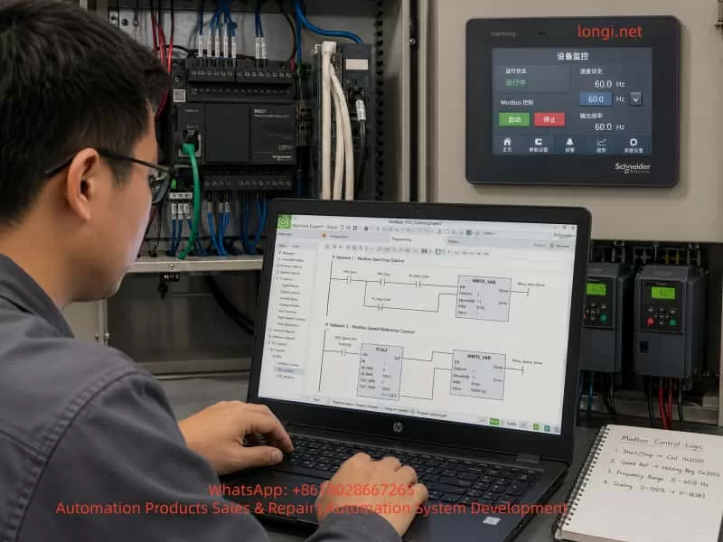
A typical system may consist of a Schneider M221 PLC as the main controller, an LU9GC3 as the Modbus RTU distribution module, several variable frequency drives as Modbus slaves, and a Schneider Harmony HMI as the operator interface. In this type of project, the key is not only how to draw the ladder logic. The complete engineering work must include communication architecture, Modbus address planning, drive parameter settings, PLC logic structure, relay feedback wiring, HMI design, power supply verification and step-by-step commissioning.


Chinese engineer commissioning a Schneider M221 PLC and multiple ATV310 VFDs in an industrial Modbus RTU control cabinet.

1. Correct System Architecture: PLC as Master, Drives as Slaves, HMI as Operator Interface

In a Modbus RTU system, there must be only one master on the same serial bus. The master sends read and write requests, and the slaves only respond to the master. In this application, the correct structure should be:

Schneider Harmony HMI
        ↓
Ethernet or HMI communication to PLC
        ↓
Schneider M221 PLC / TM221CE24R
        ↓
Modbus RTU Master
        ↓
Schneider LU9GC3 Modbus distribution module
        ↓
Multiple VFDs as Modbus RTU slaves

The HMI should not directly control all the drives on the Modbus RTU line. Its function is to send operator commands to the PLC, such as start, stop, reset and speed reference. The PLC then processes the logic and sends Modbus commands to the drives. The PLC also reads the drive status and sends this information back to the HMI for display.

A common misunderstanding in the field is confusing “HMI” with “HDMI.” HDMI is a video interface. HMI means Human Machine Interface, which is the industrial touchscreen used for operation and monitoring. A Schneider Harmony 7-inch touchscreen is an HMI, not an HDMI control device. It should communicate with the PLC, and the PLC should handle the actual drive control.


Close-up of Schneider ATV310 Modbus wiring and R1 relay feedback terminals being checked with a test probe.

2. LU9GC3 Is Not an Ethernet Switch

The LU9GC3 module has several RJ45 ports, so it is often mistaken for a normal Ethernet switch. This is a serious misunderstanding.

The LU9GC3 is a Modbus serial distribution module, not a TCP/IP Ethernet switch. It is used to distribute one Modbus serial line to several devices such as VFDs or soft starters. It does not perform Ethernet switching, and it does not automatically convert Modbus TCP to Modbus RTU.

The correct use is:

PLC serial port / Modbus RTU master
        ↓
LU9GC3
        ↓
ATV310, ATV31P, PowerFlex 525 and other Modbus RTU slaves

The HMI should not be connected to the LU9GC3 as if it were an Ethernet network switch. If the HMI has an Ethernet port, it should normally connect to the PLC Ethernet port or to a real Ethernet switch in the PLC-HMI network. The LU9GC3 should only be used for the serial Modbus RTU connection between the PLC and the drives.


Engineer programming Modbus VFD start-stop and speed control logic in Schneider Machine Expert Basic with HMI monitoring screen.

3. Each Drive Must Have a Unique Modbus Address

A Modbus RTU bus can have multiple slave devices, but each slave must have a unique address. If two drives have the same address, both may respond when the PLC sends a request to that address. This causes communication conflicts, invalid data, timeouts or unstable operation.

For a system with five drives, the address plan can be:

DeviceSuggested Modbus Address
PowerFlex 5251
ATV310 7.5 kW2
ATV310 5.5 kW #13
ATV310 5.5 kW #24
ATV31P 5.5 kW5

The exact order is not mandatory, but two rules must be followed:

Each address must be unique.
The slave address in the PLC program must match the actual address set in the drive.

If all drives remain at the factory default address, for example address 1, communication may work when only one drive is connected. But once several drives are connected to the bus, the PLC will receive conflicting replies. This is one of the most common reasons why a single-drive Modbus test succeeds but a multi-drive network fails.


Safe VFD power supply setup showing a three-phase step-up transformer feeding PowerFlex 525 and ATV310 drives under engineer inspection.

4. Communication Format Must Be the Same for All Devices

Modbus RTU communication requires not only correct slave addresses but also identical serial settings. The main settings are:

Baud rate: 9600 or 19200
Data bits: 8
Parity: Even or None
Stop bit: 1
Protocol: Modbus RTU

A practical starting point is:

19200 bps, 8E1

or:

9600 bps, 8E1

The most important point is consistency. The PLC, ATV310 drives, ATV31P drive and PowerFlex 525 must use the same baud rate, parity and stop bit. If one device has a different communication format, that device will not respond correctly to the PLC.

For initial commissioning, it is not recommended to use a very high baud rate. A Modbus RTU network with several VFDs is exposed to electrical noise, long cables, grounding problems and shielding issues. Lower or moderate baud rates are usually more stable during commissioning. After the system is working reliably, the communication cycle and baud rate can be optimized if necessary.


5. Modbus Control Principle for Schneider ATV310

To start and control an ATV310 through Modbus, two conditions must be met.

First, the drive communication parameters must be correct.
Second, the command source and frequency reference source must be set to the communication channel.

If the drive is still configured for terminal start or keypad speed reference, the PLC may write control words and frequency references successfully, but the drive will not run. This often leads technicians to believe that the PLC program is wrong, when the real issue is the drive control channel setting.

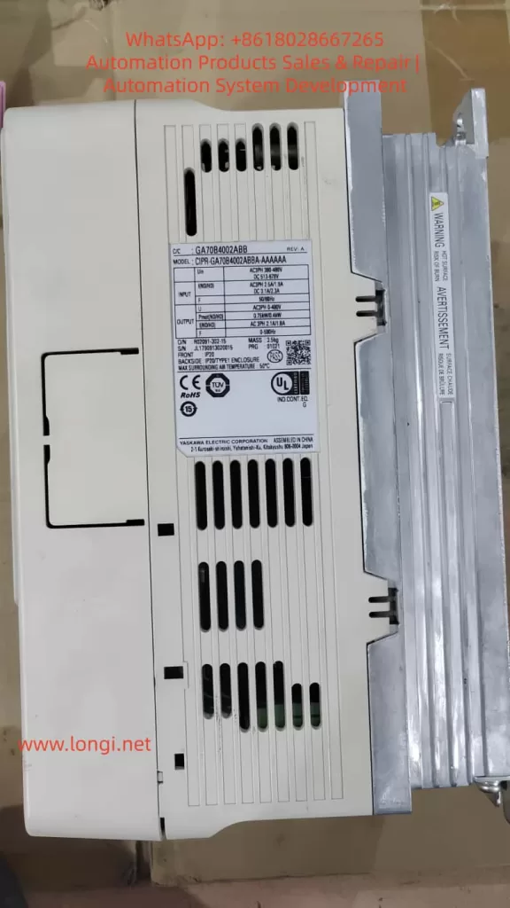
The ATV310 normally requires configuration of the following items:

Modbus slave address
Baud rate
Communication format
Command source
Frequency reference source
Control profile

In the PLC program, at least two write operations are normally required:

Write command word: start, stop, reset
Write frequency reference: for example 10 Hz, 20 Hz, 50 Hz

At the same time, the PLC should read status information:

Running status
Fault status
Actual frequency
Output current
Communication status

For the first commissioning stage, the best approach is not to build the full automatic process immediately. A safer and clearer sequence is to test one ATV310 first:

1. PLC reads the ATV310 status register successfully.
2. PLC writes a low speed reference, such as 10 Hz.
3. PLC writes a start command.
4. ATV310 starts from the PLC command.
5. PLC writes a stop command.
6. ATV310 stops from the PLC command.
7. PLC identifies drive fault or communication error.

After one ATV310 works correctly, the same logic can be copied and adjusted for the other ATV310 drives.


6. PowerFlex 525 Cannot Use the Same Register Table as Schneider ATV310

In a mixed system, the Allen-Bradley PowerFlex 525 must be treated separately. It may support Modbus, but its parameter numbers, command source settings, Modbus register addresses, speed reference scaling and status word definitions are not the same as Schneider ATV310.

This is a critical point. All VFDs are not identical just because they all use Modbus. Different manufacturers implement Modbus control in different ways. Even when they all have a command word and a speed reference, the addresses, bit definitions, scaling and command values can be different.

For PowerFlex 525, the RS485 Modbus node address is typically set in:

C124 [RS485 Node Addr]

If the PowerFlex 525 is planned as slave address 1, then:

C124 = 1

Other important parameters include:

P046 [Start Source 1]: start command source
P047 [Speed Reference 1]: speed reference source
C123 [RS485 Data Rate]: RS485 communication speed
C127 [Comm Format]: communication format
C128 [Comm Write Mode]: communication write mode

If the drive must start and receive speed reference through Modbus, the start source and speed reference source must be set to the serial or DSI communication source. Otherwise, the PLC may communicate with the drive but still fail to start it.

In the PLC program, the PowerFlex 525 should have its own control block, for example:

VFD1_PowerFlex525

It should not share the same internal register mapping as the ATV310. The external interface can look the same for all drives, such as Start, Stop, Reset, Speed_Set, Run_Status, Fault_Status and Comm_Error. But the internal Modbus read/write addresses must match the specific drive model.


7. Recommended PLC Program Structure: Common Interface, Separate Drive Blocks

In a multi-drive system, the operator wants a consistent HMI interface, but each drive may require different Modbus registers. The best PLC structure is therefore:

Common HMI interface
Different internal Modbus blocks for each drive

For example, the HMI can provide the same commands for every VFD:

Start
Stop
Reset
Speed reference
Running status
Fault status
Communication status
Actual frequency
Actual current

But inside the PLC, each drive should have its own logic section or function block:

VFD1_PowerFlex525
VFD2_ATV310_7K5
VFD3_ATV310_5K5
VFD4_ATV310_5K5
VFD5_ATV31P_5K5

Each block should handle:

1. Generate internal run command from HMI request.
2. Check permissive conditions.
3. Generate the correct command word for that drive.
4. Write speed reference.
5. Read status word.
6. Decode running and fault states.
7. Detect communication error.
8. Send status back to the HMI.

This structure keeps the main program clear. The HMI remains consistent, while the brand-specific details are isolated inside each drive control block.


8. Ladder Logic Should Not Copy a Direct Motor Starter Diagram

A normal motor starter ladder diagram usually contains:

Start button → latch circuit → contactor output
Stop button → break output
Timer → start next motor

This logic is useful for learning ladder basics, but it cannot be directly used for Modbus drive control. A Modbus-controlled VFD does not start because a PLC output coil turns on. It starts because the PLC writes the correct command word to the correct Modbus register.

The correct logic should be:

Start button or HMI start command
        ↓
PLC internal run command
        ↓
Check safety and permissive conditions
        ↓
Write drive command word
        ↓
Write frequency reference
        ↓
Read drive status word
        ↓
Display running, stopped, fault or communication error on HMI

The PLC physical outputs Q0.0, Q0.1, etc. may not be used for drive start at all. The main control is through Modbus. Physical inputs and outputs are mainly used for emergency stop, interlock, relay feedback and backup hardwired protection.

A basic internal run latch can be designed with the following conditions:

Start condition:
HMI_START = 1
Emergency stop OK = 1
Drive R1 feedback OK = 1
Modbus communication OK = 1
Drive fault = 0

When all conditions are satisfied:

RUN_CMD = 1

Stop conditions include:

HMI_STOP = 1
Emergency stop active
R1 feedback abnormal
Communication fault
Drive fault

If any stop condition is present:

RUN_CMD = 0

Then the Modbus command is generated from RUN_CMD:

RUN_CMD = 1 → write start command
RUN_CMD = 0 → write stop command

The frequency reference is written separately, for example:

HMI_SPEED_SET = 10.0 Hz
PLC converts it to the correct register value
PLC writes it to the drive speed reference register

9. R1 Relay Feedback Is Auxiliary Protection, Not a Replacement for Modbus Status

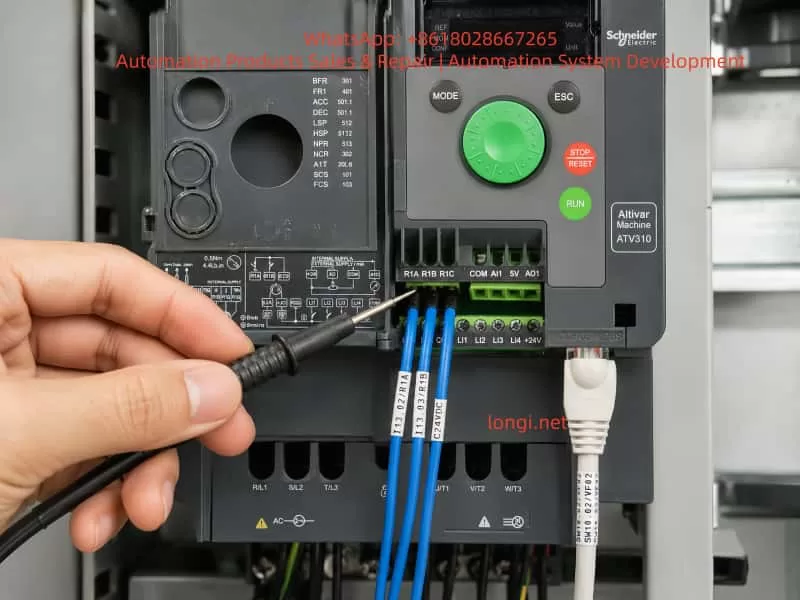
The ATV310 has relay terminals R1A, R1B and R1C. In most cases:

R1C = common
R1A = normally open contact
R1B = normally closed contact

R1A and R1B are not two separate fault signals. They are opposite contacts of the same relay. If R1C is connected to +24 V, R1A is connected to one PLC input, and R1B is connected to another PLC input, the two inputs will normally show opposite states.

For example:

Relay energized: R1A-R1C closed, R1B-R1C open
Relay de-energized: R1B-R1C closed, R1A-R1C open

In practical engineering, one contact per drive is normally enough for a fault or permissive feedback signal. A normally closed contact is often preferred for protection because a broken wire can also be detected as an abnormal condition.

A typical connection can be:

+24 V → R1C
R1B → PLC input
PLC input common → 0 V

However, the actual meaning of the input depends on how the drive relay function is configured. The R1 relay can be assigned to fault, run, ready, frequency reached or other functions. The PLC program must clearly define what the input means. It should not mix “running feedback,” “fault feedback” and “start permissive” without clear logic.

The best practice is to use both Modbus status and relay feedback:

Modbus status word: running, stopped, fault code, frequency, current
R1 relay: hardwired permissive or fault protection

If only R1 is used, the PLC cannot know the detailed fault. If only Modbus is used, a communication failure may remove an important hardwired protection path. Combining both gives a more robust system.


10. Each VFD Should Have Its Own Fault Feedback Input

For a five-drive system, each drive should ideally have a separate relay feedback input to the PLC:

VFD1 R1 → PLC input
VFD2 R1 → PLC input
VFD3 R1 → PLC input
VFD4 R1 → PLC input
VFD5 R1 → PLC input

This allows the HMI to display:

VFD1 fault
VFD2 fault
VFD3 fault
VFD4 fault
VFD5 fault

If all R1 contacts are combined into one general fault input, the PLC will only know that one drive has a problem, but it will not know which one. This makes troubleshooting slower and less professional.

If PLC inputs are limited, a compromise can be made. Critical drives can have separate hardwired feedback, while less critical devices can rely on Modbus status. But in a new system design, saving a few input points should not be more important than clear fault diagnosis.


11. Modbus Wiring Must Consider Bus Topology, Shielding, Termination and Grounding

RS485 / Modbus RTU wiring is simple in principle, but it is sensitive to poor installation. VFDs are strong sources of electrical noise. PWM motor cables, braking resistors, contactor coils, grounding problems and power harmonics can all affect communication quality.

Important wiring rules include:

  1. Use twisted shielded cable for RS485 communication.
  2. Do not run communication cable parallel to motor power cables for long distances.
  3. Keep the bus structure clear and avoid random star wiring.
  4. Use termination resistors at the ends of the bus when required.
  5. Handle shield grounding correctly to avoid ground loops.
  6. Do not reverse D0 and D1.
  7. Do not treat RJ45 Modbus ports as normal Ethernet ports.
  8. Each slave address must be unique.
  9. All serial settings must be the same.
  10. Add one device at a time during commissioning.

Many Modbus failures are not caused by the PLC program. They are caused by wiring topology, shielding, grounding, termination or duplicated addresses. When five VFDs are connected to the same bus, it is much better to add and test one device at a time.


12. Commissioning Should Start with One Drive, Not the Entire System

A reliable commissioning sequence is essential. The recommended order is:

  1. Confirm PLC model, HMI model, VFD models and communication interfaces.
  2. Confirm the function and wiring of the LU9GC3.
  3. Connect only one ATV310 first.
  4. Set its Modbus address, baud rate, parity and stop bit.
  5. Set its command source and speed reference source to Modbus.
  6. Configure the M221 serial line as Modbus RTU master.
  7. Read one status register from the ATV310.
  8. Write a low frequency reference, such as 10 Hz.
  9. Write the start command.
  10. Confirm that the drive starts.
  11. Write the stop command.
  12. Confirm that the drive stops.
  13. Read fault and running status.
  14. Copy the logic to the other ATV310 drives.
  15. Commission the ATV31P separately.
  16. Commission the PowerFlex 525 separately.
  17. Integrate the HMI operation screen and alarm screen.
  18. Test emergency stop, communication loss, relay feedback and fault reset.
  19. Finally run the motors under correct power supply conditions.

The worst approach is to connect all five drives, write all the logic, power everything up and then start troubleshooting. When many problems exist at the same time, it becomes difficult to know whether the fault is caused by addressing, parameters, wiring, registers, power supply or logic.


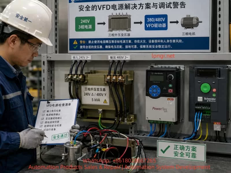
13. Do Not Run VFDs from an Improvised Single-Phase Capacitor Supply

In some field situations, the available power supply may not match the VFD input voltage. For example, the site may only have 240 V three-phase power, while the drives or equipment require 380 V, 400 V or 480 V three-phase input. Sometimes a technician may try to create a temporary “480 V single-phase” supply and use a capacitor to simulate a missing phase.

This is not a proper power supply for VFD operation.

A VFD input rectifier requires a stable and balanced AC power source. A single-phase high-voltage supply with a capacitor does not become a real three-phase supply. It may cause:

Severe input voltage imbalance
DC bus ripple
Input phase loss fault
Undervoltage or overvoltage fault
Rectifier bridge overheating
Pre-charge circuit damage
Capacitor overheating or explosion
Ground fault or leakage trip
Permanent drive damage

If the site only has 240 V three-phase power and the drives require 380/400/480 V three-phase input, the correct solution is:

240 V three-phase supply
        ↓
Three-phase step-up transformer
        ↓
380/400/480 V three-phase supply
        ↓
VFD input

A properly sized three-phase transformer, correct grounding and correct protection devices are required. PLC, HMI and Modbus communication can be tested first without running the motor. High-voltage drive operation should only be tested when the power supply is correct and safe.


14. HMI Design Should Include Operation, Status and Alarms

In a multi-drive system, the HMI should not only have start and stop buttons. A practical HMI should include operation commands, real-time status and alarm information.

Single-Drive Control Area

Each VFD should have its own control section:

Start
Stop
Reset
Speed reference
Forward / reverse selection
Manual / automatic mode

Single-Drive Status Area

Each VFD should display:

Communication OK / communication fault
Running / stopped
Fault status
Actual frequency
Output current
Output voltage
Fault code
R1 relay input status

Overview Screen

The overview screen should show the status of all drives:

VFD1: running / fault / communication error
VFD2: running / fault / communication error
VFD3: running / fault / communication error
VFD4: running / fault / communication error
VFD5: running / fault / communication error

Alarm History

A good system should record:

Which drive faulted
Fault time
Reset time
Communication loss time
Emergency stop time

If the HMI only has start and stop buttons, maintenance personnel will not have enough information to diagnose problems quickly.


15. Example PLC Variable Planning

Clear variable naming is important for maintenance. For example, for the second drive, an ATV310, the PLC variables can be:

VFD2_Start_HMI
VFD2_Stop_HMI
VFD2_Reset_HMI
VFD2_Speed_Set
VFD2_Run_Cmd
VFD2_Command_Word
VFD2_Frequency_Ref
VFD2_Status_Word
VFD2_Running
VFD2_Fault
VFD2_Comm_Error
VFD2_R1_OK
VFD2_Actual_Freq
VFD2_Actual_Current

For the PowerFlex 525, similar naming can be used:

VFD1_Start_HMI
VFD1_Stop_HMI
VFD1_Reset_HMI
VFD1_Speed_Set
VFD1_Run_Cmd
VFD1_Command_Word
VFD1_Frequency_Ref
VFD1_Status_Word
VFD1_Running
VFD1_Fault
VFD1_Comm_Error

The naming style should be consistent. This makes it easier to copy logic, link HMI objects and troubleshoot the system later. The brand-specific differences should be handled inside the drive block, not scattered throughout the HMI and main program.


16. Run Command and Safety Permissives Must Be Separated

The PLC program should separate the operator request from the actual permission to run. An HMI start button only means the operator wants to start the drive. It does not mean the drive is allowed to start immediately.

Before the PLC sends a start command, it should check:

Emergency stop OK
Safety door OK
Drive not faulted
Communication OK
R1 feedback OK
Motor protection OK
Process conditions OK
Valid speed reference
No interlock conflict

The logic should be layered:

HMI_START → operator request
RUN_PERMISSION → permissive conditions
RUN_CMD → internal PLC run command
MODBUS_COMMAND → actual command written to the VFD

This prevents accidental operation and makes diagnostics easier. If the operator presses Start but the drive does not run, the HMI can show “start condition not satisfied” and then indicate whether the problem is R1 feedback, communication fault, emergency stop, drive fault or another interlock.


17. Stop Command Must Have Higher Priority Than Start

In any motor control system, stopping and fault handling must have higher priority than starting. The PLC logic should follow these rules:

Stop has priority over start.
Fault has priority over run.
Emergency stop has priority over normal stop.
Communication fault should inhibit start.

If HMI_START and HMI_STOP are active at the same time, the PLC should stop the drive.
If RUN_CMD is active but R1 feedback becomes abnormal, the PLC should remove the run command.
If Modbus communication is lost, the PLC should stop sending run commands and display a communication fault.

The VFD’s own communication-loss behavior should also be configured. Some drives can be set to coast stop, ramp stop, hold last command or trip on communication timeout. For most industrial systems, communication loss should cause a stop or a fault response, not continued operation with the last command.


18. Main Challenges in a Mixed-Brand VFD System

The difficulty in this type of project is not only one drive. It is the mixed-brand system. The main challenges include:

  1. Schneider ATV310 and Allen-Bradley PowerFlex 525 use different Modbus register maps.
  2. The command word bit definitions may be different.
  3. The speed reference scaling may be different.
  4. The status word decoding may be different.
  5. The fault reset command may be different.
  6. The communication parameter menus are different.
  7. Some drives default to terminal control, while others may default to keypad control.
  8. Communication timeout behavior must be configured.
  9. The HMI should be unified, but the low-level Modbus control cannot be identical.
  10. The field power supply may not be suitable for all drives.

Therefore, the project should not be reduced to “how to draw the ladder.” The complete design must include architecture, parameters, addresses, communication, power, safety and commissioning sequence.


19. Recommended Implementation Procedure

For similar projects, the following implementation procedure is recommended.

Step 1: Build a Device List

Record the following information for each device:

Brand
Model
Power rating
Input voltage
Communication interface
Modbus address
Communication format
Command source
Speed reference source

Step 2: Confirm Power Supply Conditions

Check:

Voltage level
Number of phases
Available capacity
Grounding
Circuit breaker
Leakage protection
Transformer capacity
Motor rated data

If the power supply is not suitable, fix the power supply first. Do not force the VFDs to run from an unsafe temporary source.

Step 3: Test One Drive Communication

Connect only one drive and confirm that the PLC can read and write data.

Step 4: Test One Drive Operation

Run at low frequency, preferably no load or light load, and confirm start and stop.

Step 5: Test Status Reading

Read running state, stopped state, fault state, current and frequency.

Step 6: Test R1 Relay Feedback

Create or simulate a status change and confirm that the PLC input changes correctly.

Step 7: Add Drives One by One

Add one drive to the Modbus bus at a time and test after each addition.

Step 8: Commission the HMI

Link HMI buttons, setpoints, status indicators and alarms.

Step 9: Test Safety Interlocks

Test emergency stop, communication interruption, drive fault, broken feedback wire and power recovery.

Step 10: Run with Load

Under correct three-phase power, gradually increase speed and monitor current, temperature and mechanical behavior.


20. Conclusion

Using an M221 PLC to control multiple VFDs through Modbus RTU is a practical and powerful industrial control solution. It reduces hardwiring, improves system integration, and allows the HMI to display drive status, fault information, current and frequency. But such a system cannot be understood as simply “the PLC sends one start command and the drive runs.” A reliable system must handle communication roles, unique slave addresses, serial settings, register differences, command word logic, relay feedback, HMI design, safety interlocks and correct power supply conditions.

In a mixed system using Schneider ATV310, Schneider ATV31P and Allen-Bradley PowerFlex 525, the most important rules are:

Use one clear architecture.
Assign unique slave addresses.
Keep communication settings consistent.
Use different Modbus register maps for different drives.
Build modular PLC logic.
Commission one drive at a time.

The HMI should be only the operator interface. The PLC should be the only Modbus RTU master. The drives should be Modbus slaves. The LU9GC3 should be treated as a Modbus serial distribution module, not as an Ethernet switch. The PowerFlex 525 Modbus address should be set through C124, and its start source, speed reference source and communication format must be configured separately. The ATV310 and ATV31P should be configured according to the Schneider drive communication table and control profile.

Power supply conditions must also be respected. If a drive requires 380 V, 400 V or 480 V three-phase input, but the site only has 240 V three-phase power, the correct solution is a properly sized three-phase step-up transformer. A single-phase high-voltage supply with a capacitor cannot replace a real three-phase supply and should not be used for normal VFD operation.

The safest commissioning strategy is to divide the project into small, verifiable steps. First test one drive, then expand to multiple drives. First read status, then write speed. First run at low speed, then test under load. First make communication stable, then complete the HMI and automatic logic. By following this method, a complex multi-drive Modbus RTU system can be transformed into a clear, maintainable and reliable industrial control project.

Posted on

Hardware Diagnosis of FANUC α Series Servo Amplifier 8-dot Alarm, 414 Axis Detect Error, and Repeated Fuse Blowing

1. Fault Background and Main Symptoms

On CNC machines equipped with a FANUC 18M control system, the servo system is usually composed of a PSM power supply module, SVM servo amplifiers, spindle amplifier, motor feedback circuits, and the CNC-side serial servo interface. FANUC α series servo systems are generally reliable, but once a fault occurs in the control card, power card, IPM module, auxiliary power supply, or serial feedback chain, the alarm symptoms can overlap and mislead the repair process.

The case discussed here involves a horizontal machining center using a FANUC 18M CNC system. The machine is fitted with FANUC α series servo amplifiers. The Y-axis servo amplifier is A06B-6079-H106, and the control board is A20B-2001-093.

The reported symptoms include:

  1. The Y-axis servo amplifier shows an 8-dot alarm on the seven-segment LED.
  2. The CNC screen displays 414 SERVO ALARM: Axis Detect Error.
  3. Another axis, such as B axis, also shows 351 SPC ALARM: Communication.
  4. At first, the LED flickered, then the internal fuse blew, with a burnt smell.
  5. A transistor marked C4148 on the control board was found shorted.
  6. After replacing C4148, the fuse did not blow immediately, but once the power card was connected, the amplifier again showed 8-dot, and after several minutes the fuse blew again.
  7. On the B-axis control card, when only 24V was supplied with the power card removed, the seven-segment LED showed a “-” sign. But after installing the power card, the “-” appeared briefly and then disappeared.
  8. On the CNC diagnostic monitor, one or more axes were not detectable.

These symptoms should not be treated as a simple parameter problem, encoder fault, or servo initialization issue. The combination of repeated fuse blowing, burnt smell, seven-segment 8-dot alarm, damaged transistor, and failure after installing the power card strongly indicates a real hardware fault inside the servo amplifier.

The most likely fault area is the auxiliary switching power supply, power card load, IPM/IGBT drive circuit, current detection circuit, or servo communication detection circuit.


Chinese engineer inspecting a FANUC 18M servo amplifier cabinet with the Y-axis drive showing an 8-dot alarm, indicating a FANUC alpha servo hardware fault.

2. Meaning of “L Axis” in FANUC α Servo Amplifiers

When diagnosing FANUC α series servo amplifier alarms, the terms L axis, M axis, and N axis often appear in alarm descriptions. These terms can easily be misunderstood.

They do not necessarily refer to the actual machine axes such as X, Y, Z, B, or C. Instead, they refer to the internal amplifier channels.

Generally:

Servo amplifier typeInternal channel names
Single-axis SVM1 amplifierL axis
Two-axis SVM2 amplifierL axis and M axis
Three-axis SVM3 amplifierL axis, M axis, and N axis

Therefore, if a single-axis amplifier is used for the machine Y axis, then the internal L axis of that amplifier is the machine’s Y axis.

For example, if the electrical cabinet arrangement is:

  1. First module: PSM power supply module;
  2. Second module: Y-axis single-axis servo amplifier;
  3. Third module: X/Z two-axis servo amplifier;
  4. Fourth module: spindle amplifier;

Then an 8-dot alarm on the second amplifier means the L-channel fault of that particular Y-axis amplifier. It does not mean that the machine has a separate “L axis”.

For the X/Z two-axis amplifier, the internal L and M channels must be identified by checking the motor power cable, feedback cable, CNC parameter assignment, and amplifier channel wiring. It cannot be judged only from the physical cabinet position.

This distinction is important. Otherwise, repair technicians may misinterpret “L axis” as the left-side module, left-side machine axis, or a nonexistent axis, causing the diagnosis to go in the wrong direction.


Close-up of a FANUC A20B-2001-093 control board with labeled C4148 transistor, TL1451 PWM controller, 7815F regulator, and auxiliary power circuit components under inspection

3. Relationship Between 414 Alarm and 351 Alarm

The FANUC 18M alarm 414 SERVO ALARM: Axis Detect Error is a broad servo detection alarm. It does not point to only one specific component. It means the CNC has detected a serious servo-related abnormality for one axis.

Possible causes include:

  1. Internal overcurrent in the servo amplifier;
  2. IPM or IGBT module abnormality;
  3. Current detection circuit fault;
  4. DC link voltage detection fault;
  5. Servo amplifier control power supply abnormality;
  6. Amplifier initialization failure;
  7. Serial communication failure between CNC and servo amplifier;
  8. Encoder feedback communication fault;
  9. Mismatch between CNC parameters and actual servo hardware;
  10. Failure of an upstream servo module affecting downstream detection.

The 351 SPC ALARM is usually related to serial pulse coder communication. Common causes include encoder cable failure, encoder damage, servo feedback interface fault, or CNC-side feedback communication abnormality.

In many actual repair cases, 414 and 351 appear together. This does not always mean the encoder itself is defective. If the control power supply of a servo amplifier is unstable, or if the servo communication chain is interrupted, the CNC may fail to detect downstream axes correctly and then generate both 414 and 351 alarms.

In a FANUC α servo system, several servo amplifiers may be connected in a communication chain. If the Y-axis amplifier has unstable control power, faulty serial communication, or a failed internal power supply, the following X/Z or B-axis amplifier may also become undetectable on the CNC screen. Therefore, a Z-axis or B-axis detect error does not automatically mean that the Z or B servo amplifier is the original fault.

The correct approach is to first repair or isolate the amplifier with obvious hardware failure, especially if it shows 8-dot, blows fuses, has burnt smell, and has damaged components.


Chinese technician measuring C4148 and 7815F waveforms on a FANUC Y-axis servo control board with an oscilloscope showing a 65 kHz switching signal.

4. Core Interpretation of the Y-Axis 8-dot Alarm

In this case, the Y-axis servo amplifier shows an 8-dot alarm and repeatedly blows the fuse. In FANUC α series servo amplifiers, 8-dot is typically related to inverter, IPM, overcurrent detection, or power drive section abnormality.

Although the exact meaning can vary depending on the amplifier generation and hardware version, the actual symptom combination is more important than the alarm code alone.

The key facts are:

  1. The LED initially flickered;
  2. The fuse blew;
  3. There was a burnt smell;
  4. C4148 on the control board was shorted;
  5. After replacing C4148, the amplifier still showed 8-dot when the power card was installed;
  6. The fuse blew again after a few minutes;
  7. The waveform around C4148 showed high-frequency switching pulses;
  8. The fault became worse only after the power card was connected.

These facts indicate that C4148 is unlikely to be the root cause. If C4148 were the only faulty component, replacing it should have restored stable operation. But the fault returned after installing the power card, which means the downstream load or related circuit is still abnormal.

A more reasonable conclusion is:

C4148 is being damaged by an abnormal load, short circuit, overvoltage spike, or switching power supply stress caused by the downstream power card or drive circuit.

The main suspect areas should therefore include:

  1. Power card;
  2. IPM / IGBT module;
  3. Gate drive supply;
  4. Current detection circuit;
  5. Protection feedback circuit;
  6. Secondary rectifier and filter circuit of the switching power supply;
  7. Zener diodes and clamp diodes;
  8. Optocoupler feedback circuit;
  9. Connector interface between the control card and power card.

Technician performing isolation tests on a FANUC servo amplifier power card, checking U/V/W disconnection, 24V, 15V, 5V supplies, and resistance with a multimeter.

5. Analysis of the C4148, 7815F, and TL1451 Circuit

The hand-drawn circuit shows several important components: TL1451, 7815F, C4148, TR50, TR52, TR53, L50, L51, ZD50, ZD51, D50, D51, PM50, and PM51. Combined with the oscilloscope waveform, this area is not a simple static logic circuit. It is more likely a DC-DC auxiliary switching power supply or drive supply circuit on the servo control board.

5.1 Role of TL1451

TL1451 is a PWM controller. In a servo amplifier control board, it can be used to generate high-frequency PWM signals. These PWM signals drive transistors and magnetic components to produce multiple auxiliary supplies.

These auxiliary supplies may be used for:

  1. IPM or IGBT gate drive;
  2. Current detection isolation supply;
  3. Protection and alarm detection;
  4. Power card feedback;
  5. Optocoupler isolation circuits;
  6. Internal fault detection circuits.

The oscilloscope waveform showed that the base and emitter of C4148 had a pulse around 65 kHz. This matches the behavior of a PWM switching power supply. Therefore, TL1451 is at least oscillating, and the drive stage is working.

However, PWM waveform presence does not mean the power supply is healthy. If the secondary rectifier, filter capacitor, zener clamp, optocoupler feedback, or power card load is abnormal, TL1451 may continue to output PWM until the transistor, fuse, resistor, or another protection component fails.

5.2 Condition of 7815F

The measured waveform shows that the 7815F input is around 24V, and the output is around 15V. Both are relatively stable.

This indicates that the 24V-to-15V linear regulator stage is basically working at the moment of measurement.

If 7815F were the main faulty component, typical symptoms would include:

  1. No 15V output;
  2. Output voltage much lower than normal;
  3. Large output ripple;
  4. Voltage collapse after loading;
  5. Severe heating of the regulator.

Since the 15V output is currently stable, 7815F should not be treated as the primary suspect. It is more likely providing supply voltage to TL1451 or nearby control circuits.

5.3 Meaning of the C4148 Waveform

The waveform on the base and emitter of C4148 shows a high-frequency pulse with about 30V peak-to-peak amplitude. If C4148 were used as a normal low-voltage transistor switch, such a waveform would be abnormal. A normal transistor base-emitter junction usually has about 0.6V to 0.8V forward voltage, and its reverse withstand voltage is limited.

Therefore, C4148 is probably located in a floating switching node, push-pull drive node, or transformer primary drive node.

Its failure may be caused by:

  1. Excessive switching current due to downstream short circuit;
  2. High leakage spike from a magnetic component;
  3. Failed clamp diode or zener diode;
  4. Cross-conduction in the transistor drive stage;
  5. Abnormal PWM duty cycle;
  6. Optocoupler feedback failure;
  7. Power card auxiliary supply being pulled down;
  8. IPM drive supply short circuit.

This also explains why replacing C4148 alone did not solve the fault.


6. Why the Fault Becomes Worse After Installing the Power Card

A key observation is that when the control card is powered alone, some voltages and waveforms can be established. But once the power card is installed, the Y-axis amplifier shows 8-dot and then blows the fuse. The B-axis has a similar pattern: the control card can display “-” with only 24V, but the display disappears after installing the power card.

This type of symptom usually means:

The power card or one of its connected loads is pulling down an auxiliary supply generated by the control board.

Possible causes include:

  1. Short circuit in the IPM/IGBT drive circuit on the power card;
  2. Shorted rectifier diode in the drive supply;
  3. Leaky electrolytic or tantalum capacitor;
  4. Shorted optocoupler or isolation amplifier;
  5. Faulty current detection circuit;
  6. Abnormal IPM alarm feedback line;
  7. Leakage inside the IPM auxiliary terminal;
  8. Contaminated, burnt, or bent connector pins between the control card and power card;
  9. Low resistance on a 5V, 15V, 24V, or isolated drive supply line.

The fact that the fault becomes severe only after the power card is installed is very important. It means the repair should not stay only at the small components on the control board. If C4148, fuses, or resistors are replaced repeatedly without checking the power card load, the fault will return and may damage more parts.


7. Fuse Blowing Must Not Be Solved by Using a Thicker Fuse

In this case, the fuse was reportedly changed to “0.12 mm diameter × 2 strands”, and then it no longer blew immediately, but the amplifier still showed 8-dot.

This approach is risky.

The fuse is not only there to allow the machine to power up. Its function is to limit fault energy when a downstream circuit has a short. If a thicker fuse is installed without removing the fault, the result may be:

  1. A small fault becomes a large burnt area;
  2. The switching transistor fails again;
  3. PCB copper tracks are damaged;
  4. The IPM module receives secondary damage;
  5. The CNC-side servo interface or communication circuit is damaged;
  6. The short point becomes carbonized and harder to locate.

Therefore, when a fuse repeatedly blows, the correct solution is not to increase the fuse capacity. The correct procedure is to find the overcurrent branch using resistance measurement, diode-mode testing, current-limited supply injection, thermal inspection, and circuit isolation.

Only after the root cause has been removed should the original fuse specification be restored.


8. Recommended Diagnostic Procedure

8.1 Disconnect Motor U/V/W First

The first step is to disconnect the Y-axis and B-axis motor power cables from the servo amplifiers, including U, V, and W.

This separates amplifier faults from motor, cable, or mechanical load faults.

The diagnostic logic is:

Test resultInterpretation
8-dot or fuse blowing still occurs with U/V/W disconnectedInternal amplifier fault is likely
Alarm disappears with U/V/W disconnected but returns when motor is connectedMotor, cable, or load-side fault is likely
Control power still collapses with the motor disconnectedControl card or power card auxiliary supply fault
Fault appears immediately when power card is installedPower card or internal drive load short circuit

It is not recommended to continue energizing the amplifier before disconnecting the motor power cables.

8.2 Check Motor and Cable Insulation

The motor power cable insulation should be tested between:

  1. U and PE;
  2. V and PE;
  3. W and PE;
  4. U and V;
  5. V and W;
  6. W and U.

If the insulation to ground is low, or the three-phase resistance is unbalanced, the motor or cable may have an insulation breakdown.

Important warning:

Do not use a high-voltage megger on encoder cables, feedback cables, or communication cables.
Doing so can damage the encoder and CNC feedback interface.

8.3 Check the IPM / IGBT Section

After full power-off and DC bus discharge, use a multimeter in diode mode or resistance mode to check:

  1. P-N DC bus short circuit;
  2. P-U, P-V, P-W;
  3. N-U, N-V, N-W;
  4. U/V/W phase-to-phase;
  5. U/V/W to PE;
  6. Braking circuit terminals, if applicable.

If one phase reads significantly different from the others, or if P/N to U/V/W shows near-short resistance, the IPM or IGBT module is highly suspect.

In that condition, further power-on testing may only cause more damage to the fuse, drive stage, or control board.

8.4 Check Control Board Low-Voltage Supplies

The following supplies should be measured carefully:

  1. 24V input;
  2. 15V regulated output;
  3. 5V logic supply;
  4. TL1451 Vcc;
  5. TL1451 reference voltage;
  6. C4148 collector, base, and emitter;
  7. ZD50 and ZD51 voltage;
  8. Auxiliary supply lines at the power card connector.

Measurements should be taken under different conditions:

  1. Power card removed;
  2. Power card connected;
  3. At the moment 8-dot appears;
  4. Just before the fuse blows;
  5. When the display disappears.

If the 15V or 5V collapses immediately after connecting the power card, the power card or its load is likely shorted. If the 24V current gradually increases and one component heats up, a thermal leakage fault may exist.

8.5 Measure Power Card Connector Resistance

With the machine powered off, discharged, and the power card removed, measure the resistance of the power card connector pins to 0V:

  1. 24V to 0V;
  2. 15V to 0V;
  3. 5V to 0V;
  4. Drive auxiliary supply to its reference ground;
  5. IPM alarm line to 0V;
  6. Current feedback line to 0V;
  7. Optocoupler supply line to 0V.

If one line reads only a few ohms or a few tens of ohms, follow that line to find the shorted component.

Common shorted parts include:

  1. Tantalum capacitors;
  2. Small electrolytic capacitors;
  3. Zener diodes;
  4. Rectifier diodes;
  5. Gate driver ICs;
  6. Optocouplers;
  7. IPM internal auxiliary pins.

8.6 Use Current-Limited Power Injection

Repeatedly powering the amplifier from the machine supply is dangerous. A safer method is to inject voltage into the suspected branch using a current-limited bench power supply.

Suggested starting limits:

Supply branchInjection voltageInitial current limit
5V branch3V to 5V0.2A to 0.5A
15V branch5V to 15V0.1A to 0.3A
24V branch12V to 24V0.1A to 0.5A

After injecting voltage, check which component heats up. A thermal camera, infrared thermometer, alcohol evaporation method, or careful finger temperature check can be used.

If a zener diode, capacitor, driver IC, or optocoupler heats quickly, the shorted branch has likely been found.

8.7 Analyze the Failure Mode of C4148

After C4148 fails again, it should not simply be discarded. Remove it and test the failure mode:

Failure modePossible cause
Collector-emitter shortExcessive switching current, downstream short
Base-emitter shortBase drive overvoltage or reverse breakdown
Base-collector shortSwitching spike or clamp failure
All three pins shortedSevere overcurrent or overheating
Open circuitComponent burned open after transient breakdown

If the failure mode is the same each time, it can help identify the stress direction. For example, repeated collector-emitter shorting points to the main switching current path. Repeated base-emitter damage points to the base drive or clamp circuit.


9. Independent Analysis of the B-Axis Symptom

The B-axis control card can display “-” when only 24V is applied and the power card is removed. But after the power card is installed, the “-” appears briefly and disappears.

This is different from the Y-axis 8-dot symptom, but it still points toward a hardware power supply problem.

The fact that the control card can display “-” with only 24V means that at least part of the low-voltage logic can start. But when the power card is connected, the logic supply collapses or the control card shuts down.

Possible causes include:

  1. Shorted power card;
  2. Shorted connector between control card and power card;
  3. Abnormal 5V, 15V, or 24V load on the power card;
  4. Shorted drive supply or isolated supply;
  5. IPM or gate driver IC internal short;
  6. Feedback line abnormality causing protection shutdown.

Therefore, the B-axis fault should not be diagnosed as a parameter issue first. The correct direction is to check the power card, low-voltage loading, connector resistance, and auxiliary drive supply.

If a known-good board is used for cross-testing, all short-circuit checks must be completed first. Otherwise, a good control card or power card may be damaged by the same shorted load.


10. Chain Reaction of Axis Detect Errors

In FANUC 18M servo systems, the CNC communicates with the servo amplifiers through a defined serial chain. If an upstream servo module has abnormal control power or communication, downstream axes may also become undetectable.

Therefore, when the CNC displays Z-axis detect error or B-axis detect error, it does not always mean the Z-axis or B-axis amplifier is the original fault.

In this case, the Y-axis amplifier already has clear hardware fault evidence:

  1. 8-dot alarm;
  2. Fuse blowing;
  3. Burnt smell;
  4. C4148 short circuit;
  5. Fault returns when the power card is connected.

Therefore, the Y-axis amplifier should be treated as the first priority. After the Y-axis amplifier is repaired or isolated, the technician should check whether the X/Z or B-axis alarms remain. If the downstream axes become detectable again, the previous alarms were secondary communication effects. If the alarms remain, then the corresponding axis feedback cable, encoder, amplifier, and CNC parameter configuration should be checked separately.


11. Repair Strategy and Risk Control

For this type of FANUC α servo amplifier fault, the repair principle should be:

Isolate first, then power on. Measure shorts first, then waveforms. Use current-limited testing first, then full machine testing.

11.1 Practices to Avoid

The following actions are not recommended:

  1. Repeatedly powering the amplifier directly on the machine;
  2. Replacing the fuse with a thicker one;
  3. Replacing only C4148 and continuing to test;
  4. Judging the amplifier before disconnecting the motor;
  5. Installing the power card before checking its resistance;
  6. Using a high-voltage megger on encoder cables;
  7. Swapping good and bad boards without short-circuit checks;
  8. Treating fuse blowing and burnt smell as parameter faults.

11.2 Recommended Practices

The correct repair process should include:

  1. Remove the faulty module for bench testing;
  2. Restore the original fuse specification after repair;
  3. Separate the control card, power card, and IPM for testing;
  4. Compare resistance readings with a known-good axis card;
  5. Measure TL1451-related supply and PWM signals;
  6. Measure all power card interface supply lines to ground;
  7. Find the downstream short before replacing C4148 again;
  8. Perform no-load testing before connecting the motor;
  9. Reconnect the motor only after 8-dot disappears;
  10. Finally check whether CNC 414 and 351 alarms clear.

12. Practical Fault Location Map

For this kind of failure, the suspected areas can be divided into four levels.

Level 1: Control Board Auxiliary Supply

Components to check:

  • TL1451 PWM controller;
  • C4148 / TR53 switching transistor;
  • TR50, TR51, TR52 drive transistors;
  • 7815F regulator;
  • ZD50, ZD51 zener diodes;
  • D50, D51 diodes;
  • L50, L51 magnetic components;
  • C57, C58, C59, C60, C61 capacitors;
  • PM50, PM51 optocouplers or feedback parts.

Possible faults:

  • PWM drive abnormality;
  • switching transistor overcurrent;
  • zener diode short;
  • filter capacitor leakage;
  • optocoupler feedback abnormality;
  • transformer or inductor winding fault.

Level 2: Power Card Load

Components or circuits to check:

  • 5V/15V/24V load on the power card;
  • gate driver circuit;
  • IPM alarm feedback;
  • current detection circuit;
  • isolated power supply circuit;
  • connector pins;
  • power card electrolytic and tantalum capacitors.

Possible faults:

  • low-resistance short;
  • voltage collapse after connection;
  • thermal leakage;
  • optocoupler or driver IC short;
  • connector carbonization or contamination.

Level 3: IPM / IGBT Inverter Section

Check:

  • P-N;
  • P-U, P-V, P-W;
  • N-U, N-V, N-W;
  • U/V/W phase-to-phase;
  • U/V/W to PE;
  • braking circuit.

Possible faults:

  • internal IGBT short;
  • diode failure;
  • IPM alarm output abnormality;
  • phase output leakage;
  • drive supply short inside the module.

Level 4: External Motor and Cable

Check:

  • motor winding resistance;
  • insulation to ground;
  • power cable damage;
  • coolant/oil contamination in connectors;
  • mechanical load seizure;
  • brake release condition, if the axis has a brake.

Possible faults:

  • phase-to-ground leakage;
  • phase-to-phase short;
  • cable insulation breakdown;
  • connector contamination;
  • motor internal winding damage.

13. Final Conclusion

This fault is not a simple CNC parameter issue, nor is it a normal encoder communication problem. It is a hardware fault inside the FANUC α series servo amplifier that triggers a chain of servo alarms.

The Y-axis A06B-6079-H106 amplifier shows 8-dot, blows the fuse, produces a burnt smell, and damages C4148. The fault returns after the power card is installed. These symptoms strongly indicate that the real problem is located in the power card, IPM/IGBT drive circuit, auxiliary switching power supply, current detection circuit, or protection feedback circuit.

C4148 is only one damaged component in the fault path. It should not be treated as the root cause by itself.

The hand-drawn circuit and waveform analysis further show that C4148 belongs to a high-frequency auxiliary switching power supply controlled by TL1451. The 7815F regulator has approximately 24V input and 15V output, so the linear regulator itself is not the main suspect at this stage. The more important area is the downstream load of the TL1451 switching supply, including drive transistors, magnetic components, rectifier diodes, zener clamps, filter capacitors, optocoupler feedback, and the power card interface.

The B-axis symptom, where the control card shows “-” with only 24V but shuts down after installing the power card, also points to a power card or auxiliary supply load problem. It should be diagnosed as a hardware supply-loading fault before considering CNC parameters.

The CNC 414 and 351 alarms must be interpreted together with the actual amplifier condition. If one upstream amplifier has unstable control power or communication failure, downstream axes may also become undetectable. Therefore, the amplifier with the clearest hardware fault evidence should be repaired or isolated first.

The correct repair path is:

  1. Disconnect motor U/V/W cables;
  2. Check motor and cable insulation;
  3. Measure IPM/IGBT bridge circuits;
  4. Measure control board 24V, 15V, and 5V supplies;
  5. Check TL1451 and C4148 switching supply behavior;
  6. Measure power card connector resistance;
  7. Use a current-limited bench supply to locate shorted branches;
  8. Repair the downstream fault before replacing C4148 again;
  9. Restore the original fuse specification;
  10. Perform no-load testing first;
  11. Reconnect the motor only after the 8-dot alarm disappears;
  12. Finally verify that CNC 414 and 351 alarms are cleared.

Only this layered and isolated diagnostic method can prevent repeated fuse blowing, repeated C4148 failure, and further damage to the control board, power card, IPM module, or CNC servo interface. For aging FANUC α series servo amplifiers, this approach is safer and much closer to the real root cause than blindly replacing small components or randomly swapping modules.

Posted on

Analysis and Solution Strategy for E16 Communication Abnormality Fault of Lingshida LSD-A1000 Inverter

1. Introduction

In industrial automation production, inverters serve as the core equipment for motor drive, and the stability of their communication function directly impacts the continuity of production processes and the accuracy of data transmission. The Lingshida LSD-A1000 series inverter, known for its high cost-effectiveness and stable performance, is widely used in industries such as textiles, packaging, and machine tools. However, the E16 communication abnormality fault is one of the most common issues with this series, accounting for approximately 15% to 20% of total faults. This fault causes interruptions in data transmission between the inverter and the host computer (e.g., PLC, industrial PC), leading to motor shutdowns, inability to adjust production parameters, and other problems that severely affect production efficiency. This article systematically analyzes the root causes of the E16 fault, provides step-by-step troubleshooting procedures, verifies solutions through case studies, and proposes preventive measures to guide on-site maintenance personnel.

E16 Fault of the LDS-A1000

2. Overview of E16 Fault

2.1 Fault Definition and Symptoms

According to the Lingshida LSD-A1000 inverter manual, the E16 fault code is defined as “Communication Error”. Typical symptoms include:

  • The inverter’s operation panel displays “E16” and cannot start the motor via the RUN key;
  • The host computer (e.g., PLC) fails to read the inverter’s operating parameters (e.g., frequency, current, voltage);
  • The host computer cannot send control commands (e.g., start, stop, frequency adjustment) to the inverter;
  • The communication indicator lights (e.g., RX/TX) between the inverter and the host computer do not flash or flash abnormally.

2.2 Impact of the Fault

The E16 fault disrupts production workflows. If not resolved promptly, it may trigger secondary issues such as:

  • Motor shutdowns, leading to production downtime and increased operational costs;
  • Inability to monitor motor operating status in real time, potentially causing overloads, overheating, or other faults;
  • Interruption of data transmission, affecting the statistics and analysis of production data (e.g., energy consumption, output).

3. Root Cause Analysis of E16 Fault

Based on the fault manual and on-site maintenance experience, the core causes of the E16 fault can be categorized into three major groups: abnormal host computer operationcommunication cable faults, and incorrect communication parameter settings. A detailed analysis of each category is provided below.

3.1 Abnormal Host Computer Operation

The host computer (e.g., PLC, industrial PC) acts as the “initiator” of communication with the inverter. Its operating status directly affects communication stability. Common host computer abnormalities include:

3.1.1 Power Supply Issues

  • Unstable power voltage: The host computer’s power voltage must remain stable within the rated range (e.g., AC 220V ± 10%). Excessive voltage fluctuations (e.g., beyond ± 15%) can cause the host computer’s communication interface (e.g., RS485 interface) to malfunction, preventing signal transmission or reception;
  • Incorrect power wiring: Reversing or failing to ground the host computer’s live (L), neutral (N), and earth (PE) wires can damage the interface circuit, leading to communication interruptions.

3.1.2 Software Faults

  • Communication software not running: If the host computer’s communication software (e.g., SCADA, PLC programming software) is not launched or crashes, a connection with the inverter cannot be established;
  • Incorrect software parameter configuration: Mismatched communication parameters (e.g., baud rate, data bits, stop bits) between the host computer software and the inverter result in incompatible data formats, making signal parsing impossible;
  • Software conflicts: Running multiple communication software programs (e.g., Modbus and Profibus protocols) simultaneously on the host computer occupies interface resources, causing communication errors.

3.1.3 Interface Damage

  • Physical interface damage: Bent, oxidized, or burnt pins on the host computer’s RS485 interface interrupt signal transmission;
  • Interface driver circuit damage: Overvoltage or overcurrent can damage the host computer’s RS485 driver chip (e.g., MAX485), preventing the conversion of TTL signals to RS485 differential signals.
Engineer on-site repairs LSD-A1000 frequency converter

3.2 Communication Cable Faults

Communication cables serve as the “signal channel” between the inverter and the host computer. Their connection status directly impacts communication quality. Common cable faults include:

3.2.1 Incorrect Wiring

  • Reversed A/B wires: RS485 communication uses differential signal transmission. The A wire (positive signal) and B wire (negative signal) must be connected correspondingly (inverter’s A to host computer’s A, inverter’s B to host computer’s B). Reversing them causes signal polarity mismatches, making it impossible for the inverter to recognize host computer commands;
  • Unshielded cables: The shielding layer of RS485 communication cables must be grounded at one end (usually the inverter’s PE terminal). Failing to ground the shielding layer allows external electromagnetic interference (e.g., high-frequency noise from motor startup) to enter the cable, causing signal errors;
  • Loose connections: Loose wiring terminals (e.g., inverter’s TXD/RXD terminals, host computer’s RS485 terminals) result in poor contact and signal interruptions.

3.2.2 Cable Damage

  • Broken wires: Pulling, squeezing, or rodent damage can break the internal conductors of the communication cable, interrupting signal transmission;
  • Short circuits: Shorting the A/B wires of the communication cable to power lines (e.g., AC 220V) or earth wires shorts the signal, preventing it from reaching the inverter;
  • Insulation aging: The insulation layer of the communication cable ages and cracks after long-term use (e.g., over 5 years), causing signal leakage and degraded communication quality.

3.3 Incorrect Communication Parameter Settings

Communication parameters are the “language rules” between the inverter and the host computer. Mismatched parameters prevent the two devices from “communicating.” The Lingshida LSD-A1000 inverter’s communication parameters are primarily stored in the P0 group (parameter numbers P0.00 to P0.15). Common parameter errors include:

3.3.1 Incorrect Communication Address

  • Mismatched inverter and host computer addresses: The inverter’s communication address (P0.01) must match the slave address set in the host computer software (e.g., if the inverter is set to 1, the host computer must also be set to 1). A mismatch prevents the host computer from identifying the inverter, causing communication interruptions;
  • Address conflicts: When multiple inverters are connected to the same host computer, duplicate addresses (e.g., two inverters both set to 1) cause communication conflicts, triggering the E16 fault.

3.3.2 Baud Rate Errors

  • Mismatched baud rates: The baud rate (P0.02) is the data transmission rate of the communication parties (e.g., 9600, 19200, 115200 bps) and must be identical. If the inverter is set to 9600 and the host computer to 19200, data bit synchronization fails, making signal parsing impossible;
  • Baud rate out of range: The Lingshida LSD-A1000 inverter supports a baud rate range of 1200 to 115200 bps. Setting a baud rate beyond this range (e.g., 230400 bps) renders the communication module inoperable.

3.3.3 Errors in Data Bits, Stop Bits, and Parity Bits

  • Mismatched data bits: The number of binary bits per character (data bits, P0.03) must match between the inverter and the host computer (e.g., 7 bits or 8 bits). A mismatch (e.g., inverter set to 7 bits, host computer to 8 bits) causes character parsing errors;
  • Mismatched stop bits: The number of idle bits after character transmission (stop bits, P0.04) must be consistent (e.g., 1 bit or 2 bits). A mismatch (e.g., inverter set to 1 bit, host computer to 2 bits) causes character boundary recognition errors;
  • Incorrect parity bits: Parity bits (P0.05) are used to detect data transmission errors (e.g., no parity, odd parity, even parity). A mismatch (e.g., inverter set to even parity, host computer to odd parity) causes parity check failures, leading to communication interruptions.

4. Troubleshooting Steps and Case Verification for E16 Fault

4.1 Troubleshooting Steps

Troubleshooting the E16 fault should follow the principle of “from simple to complex, from external to internal,” checking the host computer, communication cables, and parameter settings in sequence. Specific steps are as follows:

Step 1: Check Host Computer Operation Status

Objective: Confirm whether the host computer can normally send/receive communication signals.
Procedure:

  1. Check power supply: Use a multimeter to measure the host computer’s power voltage (AC 220V) and ensure it is stable within the rated range (± 10%); check if the power wiring (L, N, PE) is correct and the earth wire is grounded (grounding resistance ≤ 4Ω).
  2. Check software: Confirm that the host computer’s communication software (e.g., KingView, STEP 7) is running and that the software’s communication parameters (baud rate, data bits, stop bits, parity) match the inverter; close unnecessary software (e.g., antivirus, office software) to avoid resource occupation.
  3. Check interface: Observe the host computer’s RS485 interface indicator lights (e.g., RXD, TXD). If the lights do not turn on, use a multimeter to measure the interface’s power voltage (e.g., DC 5V) to confirm if the interface circuit is normal; replace the RS485 interface module if the interface is damaged.

Step 2: Check Communication Cable Connection Status

Objective: Confirm whether the communication cable can normally transmit signals.
Procedure:

  1. Power off inspection: Turn off the power to the inverter and host computer to avoid electric shock;
  2. Check wiring: Refer to the inverter’s wiring diagram (e.g., Figure 1) to confirm correct connection of the communication cable’s A/B wires (inverter’s TXD to host computer’s RXD, inverter’s RXD to host computer’s TXD); check if the shielding layer is grounded at one end (connected to the inverter’s PE terminal); tighten the wiring terminals to avoid looseness.
  3. Test cable continuity: Use a multimeter’s continuity mode to measure the A/B wires of the communication cable (inverter side and host computer side) and confirm there are no broken wires; use a megohmmeter to measure the insulation resistance between the A/B wires and power/earth wires (≥ 1MΩ) to confirm no short circuits.
  4. Replace communication cable: If the cable is damaged (e.g., broken wires, aged insulation), replace it with a new RS485 shielded cable of the same specification (e.g., 2×1.5mm² shielded wire).

Step 3: Check and Correct Communication Parameter Settings

Objective: Ensure the inverter’s communication parameters match the host computer.
Procedure:

  1. Read inverter parameters: Read the P0 group parameters (e.g., Table 1) via the inverter’s operation panel or use the inverter’s dedicated software (e.g., LSD-Config) to connect to the inverter and read parameters;
  2. Compare host computer parameters: Contrast the inverter’s parameters with those set in the host computer software to identify inconsistencies;
  3. Modify parameters: Adjust the inverter’s parameters via the operation panel (steps below) or use dedicated software to modify and download parameters to the inverter:
    • Press the “PRG” key to enter parameter setting mode;
    • Use the “↑/↓” keys to select P0 group parameters (e.g., P0.01);
    • Press the “DATA/ENT” key to enter the parameter modification interface;
    • Use the “↑/↓” keys to adjust the parameter value and the “SHIFT” key to switch parameter bits;
    • Press the “DATA/ENT” key to save the parameter and the “ESC” key to exit.

4.2 Case Verification

Case Background: An LSD-A1000-3KW inverter (controlling a textile machine motor) in a textile factory experienced an E16 fault, causing the textile machine to shut down and affecting production.
Troubleshooting Process:

  1. Check host computer: The host computer (industrial PC) had a stable power voltage (AC 220V), the communication software (KingView) was running, and the software parameters (baud rate 9600, data bits 8, stop bits 1, even parity) matched the inverter manual; the interface indicator lights (RXD, TXD) flashed normally, so the host computer was initially deemed normal.
  2. Check communication cable: After powering off, the wiring was inspected, and it was found that the inverter’s TXD (A wire) was connected to the host computer’s RXD (B wire), and the inverter’s RXD (B wire) was connected to the host computer’s TXD (A wire)—A/B wires were reversed. After re-wiring, the E16 fault persisted when power was restored.
  3. Check parameter settings: The inverter’s P0 group parameters were read via the operation panel, and it was found that P0.02 (baud rate) was set to 9600, while the host computer software’s baud rate was set to 19200—baud rate mismatch. After changing the inverter’s P0.02 to 19200 and saving the parameters, the E16 fault was resolved, and communication between the inverter and the host computer returned to normal.

5. Preventive Measures and Maintenance Suggestions for E16 Fault

To prevent the occurrence of the E16 fault, regular maintenance of the inverter’s communication system is essential. Specific measures are as follows:

5.1 Regular Inspection of Communication Cable Connections

  • Monthly inspection: Check the connection status of the communication cable once a month to ensure correct A/B wire connection, proper grounding of the shielding layer, and no loose wiring terminals;
  • Quarterly testing: Use a multimeter to measure the continuity and insulation resistance of the communication cable every quarter to ensure no damage;
  • Annual replacement: If the communication cable has been in use for more than 3 years, replace it with a new RS485 shielded cable to avoid insulation aging-related faults.

5.2 Regular Verification of Communication Parameters

  • Parameter backup: Back up the P0 group communication parameters (e.g., export via dedicated software) during initial inverter debugging to avoid parameter loss;
  • Semi-annual核对: Check the communication parameters (baud rate, data bits, stop bits, parity, address) between the inverter and the host computer every six months to ensure consistency;
  • Modification records: Record the time, operator, and content of any parameter modifications to avoid accidental misoperations.

5.3 Maintain Stable Host Computer Operation

  • Weekly reboots: Reboot the host computer weekly to clear software cache and avoid software conflicts;
  • Software updates: Promptly update the host computer’s communication software (e.g., KingView patches) to fix software vulnerabilities;
  • Avoid overloading: Install the host computer in a well-ventilated environment to prevent hardware damage due to high temperatures; do not run unrelated software (e.g., games, videos) on the host computer to avoid CPU overloading.

5.4 Establish a Fault Log

  • Record faults: Document the occurrence time, symptoms, troubleshooting process, and solution for E16 faults to establish a fault log;
  • Trend analysis: Regularly analyze the fault log to identify high-frequency causes (e.g., reversed A/B wires, incorrect baud rate settings) and develop targeted preventive measures;
  • Employee training: Train operators on the common causes and simple troubleshooting methods of the E16 fault (e.g., checking wiring, restarting the inverter) to reduce downtime.

6. Conclusion

The E16 communication abnormality fault of the Lingshida LSD-A1000 inverter is essentially an interruption in signal transmission between the inverter and the host computer. Its core causes include abnormal host computer operation, communication cable faults, and incorrect communication parameter settings. The key to resolving this fault lies in comprehensive troubleshooting, narrowing down the fault range step by step from the host computer to the communication cable and then to parameter settings. Through the case verification and step-by-step guidance in this article, on-site maintenance personnel can quickly locate the root cause of the E16 fault and take effective solutions.

Furthermore, preventing the occurrence of the E16 fault is even more critical. By regularly inspecting communication cable connections, verifying parameters, maintaining stable host computer operation, and establishing a fault log, the incidence of the E16 fault can be effectively reduced, improving production efficiency. In industrial automation production, the communication stability of inverters directly affects the continuity of production processes. Therefore, it is essential to attach importance to the maintenance and management of the communication system to ensure unimpeded “dialogue” between the inverter and the host computer.

Appendix: P0 Group Communication Parameter Table for Lingshida LSD-A1000 Inverter

Parameter No.Parameter NameValue RangeDefault ValueDescription
P0.01Communication Address1~2471Slave address of the inverter
P0.02Baud Rate1200~115200 bps9600Data transmission rate
P0.03Data Bits7~88Binary bits per character
P0.04Stop Bits1~21Idle bits after character transmission
P0.05Parity Bit0~200=No parity, 1=Odd parity, 2=Even parity
P0.06Communication Mode0~300=Modbus RTU, 1=Profibus DP
P0.07Timeout Time0~65535 ms100Communication timeout (ms)
Posted on

IMS-A Series Servo Controller Er-08 Fault Analysis and Troubleshooting Guide

The Er-08 alarm on the IMS-A series servo controller from Shiguang Technology is not a typical hardware protection fault such as overcurrent, overvoltage, undervoltage, or overheating. Instead, it is mainly related to internal parameter storage, QMCL program execution, CPU operation, and RAM memory retention.

According to the IMS-A series controller documentation, Er-08 indicates a QMCL language error or parameter initialization abnormality caused by CPU interference. Common causes include severe input power interference, corrupted parameter areas, abnormal QMCL programs, insufficient RAM backup battery voltage, or internal communication abnormalities.

Unlike ordinary frequency inverters, the IMS-A controller uses digital vector control combined with QMCL motion control programming. Therefore, the controller operation depends not only on electrical hardware but also on internally stored parameters and motion programs. Once these data become corrupted or lost, the controller may fail to initialize properly and trigger Er-08.


IMS-ACT42P2WG-AG

1. Understanding the Meaning of Er-08

The IMS-A series is designed for high-performance control of AC induction motors using PG-based vector control. The controller integrates speed control, position control, torque control, programmable I/O, communication functions, and QMCL motion logic inside the controller itself.

Because of this architecture, Er-08 is fundamentally different from ordinary drive alarms.

This alarm usually means one of the following:

  • The CPU detected abnormal QMCL program execution
  • RAM parameter data became corrupted
  • Internal parameters were unexpectedly initialized
  • The controller experienced severe electrical interference
  • The RAM backup battery voltage became insufficient
  • The QMCL motion program was lost or damaged

In practical applications, Er-08 commonly appears in these situations:

  • Equipment remained powered off for a long period
  • The machine was stored for years before reuse
  • The control cabinet contains heavy electrical noise
  • Nearby contactors or braking systems generate interference
  • Parameters were modified but not properly saved
  • The controller lost RAM retention power
  • The control board suffered moisture or dust contamination

2. Why the RAM Backup Battery Is Important

The IMS-A controller stores part of its parameters and QMCL programs inside RAM memory. RAM requires continuous backup power to preserve data after shutdown.

The controller uses an onboard backup battery for this purpose.

If the battery voltage becomes low, the RAM contents may partially or completely disappear during power-off periods. When the controller powers on again, the CPU may detect invalid parameter data or corrupted QMCL instructions and generate Er-08.

The IMS-A manual specifically mentions that the RAM backup battery must maintain sufficient voltage. Long-term storage without periodic power-up may cause parameter and QMCL data loss.

This is extremely important in real maintenance work.

Many technicians repeatedly power-cycle the controller after Er-08 appears, but the alarm remains because the issue is no longer temporary interference. The internal data itself may already be corrupted.

Replacing the battery alone does not automatically restore lost parameters or QMCL programs. The original data may still need to be rewritten manually.

Older machines, second-hand equipment, spare stock units, and machines stored for years are especially vulnerable to this issue.


Er-08 Fault of the IMS-A drive

3. Difference Between Er-08 and Normal Hardware Faults

Typical servo or inverter faults usually point to specific hardware problems:

  • Overcurrent
  • Overvoltage
  • Undervoltage
  • IGBT module overheating
  • Encoder disconnection
  • Motor overload
  • Cooling fan failure

Er-08 is different.

It mainly points to software-level or memory-level abnormalities rather than direct power hardware failure.

This means the motor, encoder, power module, and braking resistor may still be physically normal while the controller itself cannot correctly execute internal logic.

However, this does not mean hardware inspection should be ignored.

Electrical noise, grounding problems, unstable control power supplies, moisture contamination, and control board deterioration can all indirectly trigger parameter corruption and CPU instability.

Therefore, Er-08 troubleshooting must combine both software and hardware inspection.


4. First Troubleshooting Step: Check Power Supply and Electrical Noise

One major cause of Er-08 is severe electrical interference entering through the input power line.

The first step should always be verifying the incoming power quality.

Check the following carefully:

  • Three-phase input voltage balance
  • Loose input terminals
  • Burned contactor contacts
  • Voltage fluctuation during startup
  • Sudden voltage dips
  • Grounding quality
  • Cabinet interference sources

Particular attention should be paid to:

  • Large contactors
  • Welding machines
  • Solenoid valves
  • Brake units
  • Large motors
  • Frequent switching loads

Poor grounding can allow common-mode noise to enter the control board and CPU circuitry.

Encoder cables, communication lines, and motor power cables should not run together in parallel for long distances.

If Er-08 appears randomly during machine operation rather than immediately after startup, electrical interference becomes highly suspect.


5. Second Troubleshooting Step: Inspect the RAM Backup Battery

For older or long-stored equipment, the RAM battery must be inspected immediately.

Important inspection points include:

  • Battery voltage level
  • Corrosion around battery terminals
  • Loose solder joints
  • Oxidized connectors
  • Signs of leakage or swelling

If the battery voltage is low, parameter retention becomes unreliable.

Even if the controller temporarily starts normally, the parameters may disappear again after shutdown.

After battery replacement, the following items must still be verified:

  • System parameters
  • Motor parameters
  • Encoder settings
  • I/O assignments
  • QMCL programs
  • Motion control logic

Battery replacement alone does not guarantee recovery.


6. Third Troubleshooting Step: Verify Controller Parameters

After Er-08 occurs, parameters may revert to defaults or become partially corrupted.

The technician must compare the current settings against original machine records.

Critical parameters include:

  • Motor rated voltage
  • Rated current
  • Encoder pulse count
  • Speed loop settings
  • Position loop settings
  • Torque limits
  • Acceleration and deceleration settings
  • I/O terminal assignments
  • Communication settings
  • QMCL execution parameters

Machines using position control, synchronization, tension control, lifting systems, or indexing systems are especially sensitive to parameter corruption.

Improper parameters may cause:

  • Wrong motor direction
  • Brake release failure
  • Limit switch malfunction
  • Mechanical collisions
  • Servo instability

The machine should never be restarted aggressively before confirming parameter correctness.


7. Fourth Troubleshooting Step: Inspect the QMCL Program

The IMS-A controller uses QMCL programming for motion logic execution.

If the QMCL program becomes corrupted, missing, or incompatible with the hardware configuration, Er-08 may appear continuously.

Possible QMCL-related causes include:

  • Program corruption
  • Incomplete writing process
  • Incorrect parameter addressing
  • Invalid jump instructions
  • Program storage failure
  • Wrong hardware type configuration
  • PG configuration mismatch
  • Incorrect I/O definitions

If the machine previously operated normally for years and suddenly developed Er-08 after long storage or power interruption, the original program itself is usually not defective. Instead, the stored data may have been lost or damaged.

In such cases, restoring the original backup program is often necessary.

Without a backup, repair becomes significantly more difficult because the QMCL program may contain custom machine logic specific to the application.


8. Recommended Repair Procedure for Er-08

A proper troubleshooting sequence is extremely important.

Step 1: Power Down Safely

Disconnect main power and wait until the DC bus fully discharges.

Step 2: Inspect Input Power

Measure three-phase voltage and confirm stable power quality.

Step 3: Eliminate Electrical Noise

Check grounding, shielding, cabinet layout, and interference sources.

Step 4: Attempt Alarm Reset

Clear the alarm only after ensuring all run commands are removed.

Step 5: Verify Parameters

Compare all important parameters with original records.

Step 6: Inspect Backup Battery

Measure battery voltage and replace if necessary.

Step 7: Restore Parameters

Rewrite original motor and control parameters.

Step 8: Restore QMCL Program

Reload the original motion control program if required.

Step 9: Perform No-Load Testing

Check motor direction, encoder feedback, and brake control.

Step 10: Perform Full Load Testing

Gradually restore full machine operation while monitoring stability.


9. Common Mistakes During Er-08 Repair

Repeated Power Cycling

If RAM data is already corrupted, repeated restarting will not solve the issue.

Ignoring the Backup Battery

Low battery voltage is one of the most common root causes.

Treating Er-08 as a Power Module Failure

Er-08 does not directly indicate IGBT damage.

Restarting Without Parameter Verification

Incorrect parameters may cause dangerous machine movement.

Ignoring QMCL Programs

Many technicians only understand inverter parameters and overlook motion logic programs.


10. Verification After Repair

Successful repair means more than simply clearing the alarm.

The following conditions should be verified:

  • No Er-08 alarm during startup
  • Parameters remain stable after power cycling
  • QMCL programs execute correctly
  • Encoder feedback operates normally
  • Motor direction is correct
  • Brake control functions properly
  • Limit switches respond correctly
  • No abnormal vibration or noise
  • Long-term operation remains stable

11. Preventive Measures

To reduce the risk of future Er-08 faults:

  • Periodically power up long-stored equipment
  • Replace aging RAM batteries proactively
  • Maintain clean and dry control cabinets
  • Separate encoder cables from motor cables
  • Use proper cable shielding and grounding
  • Install surge suppression for inductive loads
  • Maintain backups of parameters and QMCL programs
  • Reduce electrical interference inside the cabinet

For older machines, maintaining complete backups is extremely important. Losing a custom QMCL program may lead to extended downtime and difficult recovery.


12. Conclusion

The Er-08 alarm on the IMS-A series servo controller is fundamentally related to QMCL program execution, parameter initialization abnormalities, CPU interference, and RAM memory retention problems.

Unlike standard hardware protection alarms, Er-08 mainly involves the controller’s internal software and storage system.

Effective troubleshooting requires systematic inspection of:

  • Input power quality
  • Electrical interference
  • Grounding
  • RAM backup battery condition
  • Parameter integrity
  • QMCL program integrity
  • Control board condition

In many cases, especially on older or long-stored equipment, low backup battery voltage and corrupted RAM data are the primary root causes.

Maintaining stable electrical environments, proper grounding, regular maintenance, and reliable backups of parameters and QMCL programs are the most effective long-term strategies for preventing recurring Er-08 faults.

Posted on

ABB ACS510 F0009 / MOT TEMP Fault Analysis and Troubleshooting Guide for Motor Overtemperature Protection

The ABB ACS510 is one of the most widely used low-voltage AC drives in HVAC systems, water pumps, constant-pressure water supply systems, ventilation equipment, conveyor systems, industrial fans, and various variable-speed motor applications. In real industrial maintenance work, one of the most common faults encountered on the ACS510 is F0009, also displayed in the fault list as MOT TEMP or Motor Overtemperature.

According to the ABB ACS510 user manual, fault code 9 “MOT TEMP” indicates that the drive has detected a motor overheating condition based on either the internal thermal model calculation or an external temperature feedback signal. ABB recommends checking whether the motor is overloaded, adjusting parameters 3005–3009 related to the motor thermal model, and checking the temperature sensor configuration and parameter group 35 settings.

This fault is frequently misunderstood in the field. Many technicians immediately assume the inverter itself is defective as soon as F0009 appears. In reality, this fault primarily concerns the motor thermal condition rather than the ACS510 heatsink temperature. The ACS510 has separate alarms and faults for drive overtemperature conditions. F0009 specifically focuses on motor thermal protection, including real motor overheating, overload conditions, insufficient cooling at low speed, incorrect motor parameter settings, thermal model mismatch, or external temperature sensor problems.

For this reason, troubleshooting F0009 must follow a systematic process. Resetting the drive repeatedly or replacing boards without analysis often leads to wasted time, unnecessary repair costs, and even motor damage.


F0009 Fault of the ACS510 VFD

1. Understanding the Real Meaning of F0009

The ACS510 determines motor overheating in two primary ways.

The first method is the internal motor thermal model. The drive continuously estimates motor temperature based on:

  • Motor rated current
  • Output current
  • Operating frequency
  • Load conditions
  • Running time
  • Thermal characteristics

When the calculated thermal level exceeds the protection threshold, the drive first may generate a warning and eventually trips with F0009.

The second method is external temperature feedback. If the motor is equipped with a PTC thermistor, PT100 sensor, thermal switch, or other temperature feedback device, and parameter group 35 is enabled, the ACS510 can monitor actual motor temperature through the sensor input.

This explains why the same F0009 fault may have completely different causes depending on the installation.

In some cases the motor is genuinely overheating. In others the issue is caused by incorrect parameters, sensor wiring problems, or thermal model configuration errors.


2. F0009 Does Not Mean the Drive Itself Is Overheating

One of the most common mistakes in industrial troubleshooting is confusing motor overtemperature with inverter overtemperature.

F0009 is specifically related to motor thermal protection.

This does not automatically mean the ACS510 heatsink or power section is overheating.

When the drive itself overheats, troubleshooting usually focuses on:

  • Cooling fan failure
  • Heatsink dust accumulation
  • Poor cabinet ventilation
  • High ambient temperature
  • Improper installation spacing
  • Airflow obstruction

However, when F0009 occurs, the primary focus must remain on:

  • Motor temperature
  • Motor current
  • Mechanical load
  • Motor cooling
  • Thermal protection settings

Even though drive heating and motor heating can occur together under overload conditions, the diagnostic sequence should not start with inverter hardware replacement.


3. Step One: Confirm Whether the Motor Is Actually Hot

The first action after F0009 appears is to verify the real motor temperature.

Use an infrared thermometer or contact thermometer to measure:

  • Motor housing temperature
  • Front bearing temperature
  • Rear bearing temperature
  • Cooling fan area
  • Coupling or pulley area
  • Gearbox or pump bearing temperature

If the motor surface is extremely hot, bearings are overheating, or there is a strong burnt insulation smell, then the fault is likely a real overtemperature condition.

In this situation, repeatedly resetting the drive is dangerous. Continuous restarting may eventually damage motor insulation, burn the winding, or cause mechanical failure.

On the other hand, if the motor is only slightly warm and F0009 occurs quickly after startup, parameter mismatch or sensor issues become more likely.


Industrial Chinese female engineer troubleshooting an ABB ACS510 variable frequency drive inside an electrical control cabinet, measuring PCB signals with multimeter probes while the inverter display shows F0009 motor overtemperature fault.

4. Step Two: Check Whether the Motor Current Exceeds Rated Current

Motor overheating is commonly caused by overload conditions.

The ACS510 should be monitored together with an external clamp meter.

The following values must be compared:

  • Motor nameplate rated current
  • Drive output current
  • Actual measured phase current
  • Phase current balance
  • Starting current
  • Loaded operating current

If the motor is rated at 20A but continuously operates at 25A or higher, overheating is expected.

If the phase currents are significantly unbalanced, such as:

  • Phase A: 18A
  • Phase B: 25A
  • Phase C: 19A

then the problem may involve:

  • Motor winding damage
  • Loose cable connections
  • Output terminal problems
  • Contactor issues
  • Partial short circuit
  • Ground leakage

When the drive display current differs greatly from actual measured current, additional investigation of current feedback or measurement accuracy may be required.


5. Step Three: Inspect Mechanical Load Problems

Many F0009 faults are not electrical failures at all.

Mechanical overload is extremely common.

Typical causes include:

  • Pump blockage
  • Fan blade contamination
  • Damper problems
  • Bearing seizure
  • Belt overtension
  • Gearbox damage
  • Conveyor jams
  • Coupling misalignment
  • Excessive friction
  • Product buildup
  • Increased process load

The inverter only sees increased motor current and rising thermal estimation.

The drive cannot determine the exact mechanical cause.

One effective troubleshooting method is to disconnect the mechanical load temporarily and run the motor unloaded. If the current drops significantly and the overheating fault disappears, the problem is mechanical rather than electrical.


6. Step Four: Low-Speed Operation and Cooling Problems

This is one of the most overlooked causes of motor overheating in variable frequency drive systems.

Standard induction motors use shaft-mounted cooling fans.

When the motor runs at low frequency, such as:

  • 10 Hz
  • 15 Hz
  • 20 Hz

the motor cooling fan also rotates slowly.

As airflow decreases, motor cooling performance drops dramatically.

Even if the current is not extremely high, the motor may gradually overheat.

This problem is especially common in:

  • Conveyors
  • Mixers
  • Compressors
  • Extruders
  • Constant torque applications

Solutions may include:

  • Increasing minimum operating frequency
  • Installing independent cooling fans
  • Using inverter-duty motors
  • Reducing mechanical load
  • Improving ventilation
  • Cleaning motor cooling fins

If the customer reports that the fault occurs mainly during summer or after long low-speed operation, insufficient cooling is a major suspect.


7. Step Five: Verify Motor Nameplate Parameters 9905–9909

The ACS510 motor thermal model relies heavily on accurate motor data.

Incorrect motor parameter settings are a very common cause of F0009.

The following parameters must be checked carefully:

Parameter 9905 — Motor Rated Voltage

This must match the actual motor nameplate voltage.

Parameter 9906 — Motor Rated Current

This is the most critical parameter.

It must match the actual motor nameplate current.

If 9906 is set too low, the ACS510 will falsely estimate motor overheating much earlier than normal.

Parameter 9907 — Motor Rated Frequency

Usually:

  • 50 Hz
  • 60 Hz

depending on the motor.

Parameter 9908 — Motor Rated Speed

Must match the motor nameplate RPM.

Parameter 9909 — Motor Rated Power

Must match actual motor power.

Parameter mismatch frequently occurs when:

  • Motors are replaced
  • Drives are restored to factory settings
  • Used equipment is installed
  • Parameters are copied from another machine
  • Control boards are replaced

For example, if the original motor was 7.5 kW and later replaced with an 11 kW motor while the old current settings remain unchanged, the drive may falsely trip with F0009.


8. Step Six: Check Parameters 3005–3009

The ABB manual specifically recommends checking parameters 3005–3009 when F0009 occurs.

These parameters control the motor thermal protection model.

Parameter 3005 — Motor Thermal Protection

Defines how the drive reacts to thermal overload.

Disabling this protection entirely is not recommended in industrial applications unless external thermal protection exists.

Parameter 3006 — Motor Thermal Time Constant

Defines how quickly the thermal model responds.

If set too low, the drive may trip prematurely.

If set too high, motor protection may become insufficient.

Parameters 3007–3009 — Load Curve and Low-Speed Thermal Characteristics

These parameters influence low-speed motor heating estimation.

Incorrect settings can easily cause false overheating trips.

This is particularly common in:

  • Used drives
  • Systems with modified parameters
  • Equipment with undocumented adjustments

9. Step Seven: Check Parameter Group 35 and Temperature Sensors

If external motor temperature sensors are used, parameter group 35 becomes extremely important.

Common problems include:

  • Open-circuit PTC sensors
  • Incorrect sensor type configuration
  • Broken wiring
  • Loose terminals
  • Grounding problems
  • Analog input interference
  • Incorrect sensor resistance
  • Wrong terminal assignment

In some cases, parameter group 35 is enabled even though no motor temperature sensor exists.

This can directly generate false F0009 faults.

Sensor-related faults often show these characteristics:

  • Motor is physically cool
  • Fault appears immediately after startup
  • Fault changes when wiring is moved
  • Intermittent trips occur randomly

10. Distinguishing Between Alarm and Fault Conditions

The ACS510 may first display a motor overtemperature warning before finally tripping with F0009.

This progression is important.

If the fault develops gradually over time, thermal accumulation is likely.

If the drive trips immediately after startup, parameter or sensor problems are more likely.

If the fault appears mainly in hot weather or during long operating cycles, cooling and environmental conditions become key suspects.


11. Recommended Field Troubleshooting Procedure

A professional troubleshooting sequence should follow these steps:

  1. Record the fault condition.
  2. Measure actual motor temperature.
  3. Measure three-phase motor current.
  4. Inspect mechanical load conditions.
  5. Verify motor nameplate parameters 9905–9909.
  6. Check thermal model parameters 3005–3009.
  7. Inspect parameter group 35 and temperature sensors.
  8. Test the system after reset under controlled load.
  9. Perform insulation resistance testing if necessary.

This structured approach prevents unnecessary board replacement and reduces downtime.


12. Real Overheating vs False Overheating

When the motor is genuinely overheating, the root cause must be corrected physically.

Possible solutions include:

  • Reducing load
  • Repairing bearings
  • Cleaning cooling fins
  • Improving airflow
  • Replacing cooling fans
  • Upgrading motor size
  • Installing forced cooling
  • Correcting alignment
  • Repairing mechanical equipment

Simply disabling thermal protection does not solve the real problem.

When the motor is not actually overheating, the issue usually involves:

  • Incorrect motor parameters
  • Wrong thermal model settings
  • Sensor problems
  • Parameter corruption
  • Wiring errors
  • Control board feedback issues

13. Common Mistakes Made During Troubleshooting

Several mistakes appear repeatedly in industrial service work.

Mistake 1: Assuming the inverter is defective immediately

F0009 primarily concerns the motor thermal condition.

Mistake 2: Repeatedly resetting the drive

This can eventually destroy the motor.

Mistake 3: Disabling thermal protection

This removes a critical protection layer.

Mistake 4: Ignoring mechanical load

Mechanical overload is extremely common.

Mistake 5: Replacing motors without updating parameters

Parameter mismatch causes false trips frequently.

Mistake 6: Ignoring low-speed cooling limitations

This is one of the most common real-world causes.


14. Example Field Case

A water pump system using ACS510 repeatedly generated F0009 during summer operation.

The customer believed the inverter was defective.

Field inspection revealed:

  • Motor current near rated value
  • Long-term operation at 18 Hz
  • Poor ventilation
  • Standard self-cooled motor
  • High ambient temperature

The real issue was insufficient motor cooling at low speed.

The solution included:

  • Cleaning motor cooling fins
  • Improving ventilation
  • Raising minimum frequency
  • Installing independent cooling

No inverter repair was required.

In another case, a larger motor had been installed but parameter 9906 still contained the old motor current value. The drive repeatedly tripped with F0009 after several minutes of operation. Correcting the motor parameters solved the problem immediately.


15. Conclusion

ABB ACS510 fault F0009 / MOT TEMP indicates that the drive believes the motor thermal condition has exceeded safe operating limits. The drive may determine this through the internal thermal model or through external temperature feedback devices.

Successful troubleshooting requires systematic analysis of:

  • Actual motor temperature
  • Motor current
  • Mechanical load
  • Low-speed cooling capability
  • Motor nameplate parameters
  • Thermal protection settings
  • Temperature sensor circuits

The correct diagnostic philosophy is:

Verify real overheating first, then investigate false thermal estimation, and only consider inverter hardware failure after all motor-side causes have been eliminated.

In most real industrial cases, F0009 is caused by:

  • Motor overload
  • Poor cooling
  • Incorrect parameters
  • Mechanical load issues
  • Sensor configuration errors

rather than defective ACS510 hardware itself.

A structured troubleshooting process can prevent unnecessary drive replacement, reduce maintenance costs, avoid repeated downtime, and protect the motor from catastrophic thermal damage.

Posted on

ACS580 Drive RS485 (Modbus RTU) Communication Testing and Parameter Adjustment Using a Serial Assistant Tool

During industrial maintenance, second-hand drive inspection, PLC communication debugging, HMI integration, and remote technical support, engineers often need to verify whether the embedded fieldbus interface of an ABB ACS580 drive is functioning correctly. The ACS580 includes an internal EFB (Embedded Fieldbus) interface that can operate as a Modbus RTU slave. With a USB-to-RS485 converter, a computer, and a serial communication tool, it is possible to perform complete communication testing, including register reading, control word writing, frequency reference adjustment, remote start/stop control, and fault reset.

This method is extremely practical because it does not require a PLC, HMI, or ABB commissioning software. As long as the RS485 physical layer and the drive parameters are configured correctly, engineers can directly determine whether the communication port, Modbus settings, control logic, and remote control chain are operating properly.

This article explains the complete process of ACS580 Modbus RTU communication testing using a USB-RS485 converter and a serial assistant tool. It covers wiring, parameter configuration, serial software settings, Modbus frames, control word logic, startup and stop procedures, common faults such as 6681 EFB communication loss and AFE1/off2 emergency stop, as well as communication instability caused by electromagnetic interference during drive operation.


Schematic diagram of ACS580 frequency converter EFB interface and USB-RS485 wiring

1. ACS580 EFB Interface and RS485 Wiring

The ACS580 control board includes a three-pin EFB terminal used for embedded fieldbus communication. This interface can be used directly for Modbus RTU testing.

Typical terminal definitions are:

ACS580 TerminalFunction
29B+
30A-
31DGND

The wiring between the ACS580 and the USB-RS485 converter is typically:

ACS580 X5/EFBUSB-RS485 Converter
29 B+RS485 A/B
30 A-RS485 opposite line
31 DGNDGND

One important point is that many USB-RS485 converters use inconsistent A/B or D+/D- labeling. Cheap converters especially may reverse the line naming compared to the drive definition. Therefore, if the parameters and serial settings appear correct but no communication occurs, the first troubleshooting step should be swapping the A and B communication wires.

For single-drive bench testing, it is recommended to enable both TERM and BIAS on the ACS580 communication interface. This improves communication stability in short-distance point-to-point testing.

For long-term industrial use, twisted-pair shielded cable should be used for the A/B communication pair. The shield should typically be grounded at one end only to avoid ground loop current.


ACS580 Modbus RTU Testing Tool

2. ACS580 Parameters Required for Modbus RTU Communication

To allow Modbus RTU control, the embedded fieldbus interface must first be enabled and configured correctly.

Recommended communication parameters:

ParameterRecommended ValueDescription
58.01 Protocol EnableModbus RTUEnable embedded fieldbus
58.03 Node Address1Modbus slave address
58.04 Baud Rate9.6 kbpsMatches serial tool setting
58.05 Parity8 Even 1Matches serial tool
58.06 Communication ControlRefresh SettingsApply communication changes
58.25 Control ProfileABB DriveEnables ABB control word format

After modifying the 58-group parameters, 58.06 “Refresh Settings” must be executed, or the drive must be power-cycled. Many communication failures occur simply because the communication settings were not refreshed.

The command source and frequency reference source must also be assigned to EFB:

ParameterRecommended ValueDescription
19.11 EXT1/EXT2 SelectionEXT1Use external control set 1
20.01 EXT1 CommandsEmbedded Fieldbus / EFBStart/stop via Modbus
28.11 EXT1 Frequency Reference 1EFB Reference 1Frequency reference from Modbus
19.01 Operating ModeScalar Hz / Speed ModeCommon for testing

If 20.01 is not assigned to EFB, the drive may acknowledge Modbus commands without actually starting. If 28.11 is not assigned to EFB Reference 1, writing frequency values may not affect the drive output.

During testing, it is also recommended to temporarily disable communication-loss trips:

ParameterRecommended Temporary Value
58.14 Communication Loss ActionNo Action
58.15 Communication Loss ModeAny Message
58.16 Communication Loss Time30 seconds or longer

This prevents fault 6681 from occurring while manually testing communication using a serial tool.


AFE1 ALARM

3. Serial Assistant Software Configuration

The USB-RS485 converter driver must first be installed so that Windows recognizes the device as a COM port.

Typical serial settings:

SettingValue
COM PortCOM3 / COM4 / etc.
Baud Rate9600
Data Bits8
ParityEven
Stop Bits1
Flow ControlNone
Send FormatHEX
Receive FormatHEX

If ACS580 parameter 58.05 is set to “8 Even 1,” the serial assistant must also use Even parity. A parity mismatch will prevent proper communication.

Another critical point involves CRC handling. Some serial tools automatically append Modbus CRC bytes. If CRC auto-generation is enabled, the user should only enter the Modbus frame without CRC. If the complete frame including CRC is entered manually while auto-CRC is still enabled, the resulting frame becomes invalid.

Example read command:

01 03 00 00 00 06 C5 C8

If CRC auto-generation is disabled, the complete frame above should be transmitted exactly as shown.


6681 Fault

4. Read Registers Before Attempting Startup

The first communication test should always be a register read operation rather than an immediate start command.

Command for reading registers 400001–400006:

01 03 00 00 00 06 C5 C8

Frame meaning:

BytesDescription
01Slave address
03Read holding registers
00 00Starting register
00 06Read 6 registers
C5 C8CRC

A typical response:

01 03 0C 00 00 00 00 00 00 00 00 11 33 00 00 95 E4

If the drive responds, the physical layer, slave address, baud rate, parity, and CRC are likely correct.

ACS580 communication diagnostics can also be monitored:

ParameterDescription
58.08 Received PacketsValid incoming frames
58.09 Sent PacketsValid outgoing frames
58.11 UART ErrorsSerial framing/parity errors
58.12 CRC ErrorsInvalid CRC or communication noise

5. Writing Frequency References

Under the ABB Drive profile, the frequency scaling is typically:

50Hz = 20000

Frequency calculation:

Reference Value = Target Frequency / 50 × 20000

Example for 10Hz:

10 / 50 × 20000 = 4000

4000 decimal equals 0FA0 hexadecimal.

Command to write 10Hz into register 400002:

01 06 00 01 0F A0 DD 82

The drive should echo the same frame back if the command is accepted.

Common frequency conversions:

FrequencyDecimalHEX
5Hz200007D0
10Hz40000FA0
20Hz80001F40
30Hz120002EE0
50Hz200004E20

6. Control Word Logic: Reset, Run, and Stop

The ACS580 control word is the key element for remote control via Modbus.

Common control words:

Control WordFunction
04F7Fault Reset
047FRun
047EStop

Fault reset command:

01 06 00 00 04 F7 CA 8C

Run command:

01 06 00 00 04 7F CA EA

Stop command:

01 06 00 00 04 7E 0B 2A

For stable operation, it is better to periodically write both control word and frequency reference together using Modbus function code 10.

10Hz run command:

01 10 00 00 00 02 04 04 7F 0F A0 C6 CF

Stop and zero-frequency command:

01 10 00 00 00 02 04 04 7E 00 00 92 87

In practical testing, a periodic transmission interval of 200–500ms proved much more stable than one-shot commands. With a 1-second interval, the panel sometimes displayed the frequency reference without actual output. At 500ms intervals, the drive produced stable output frequency and cooling fan operation.


7. Understanding Fault 6681: EFB Communication Loss

Fault 6681 indicates that the drive detected a communication loss on the embedded fieldbus.

Typical causes:

  1. The drive command source is assigned to EFB, but the PC is not continuously transmitting Modbus frames.
  2. Communication-loss action remains enabled during manual testing.
  3. Parameters were copied from another drive, but no real-time control word is being transmitted after power-up.

During manual testing, it is recommended to disable communication-loss trips temporarily. However, in actual industrial applications, communication supervision should remain active and PLCs should continuously refresh control words and references.


8. Understanding AFE1 / OFF2 Emergency Stop

Another common issue is the AFE1 warning showing “Emergency Stop OFF2.”

This is not always caused by hardware emergency stop wiring. It can also occur when the fieldbus control word is incomplete or invalid.

Example:

06.01 = 408 hex

In this state, Off1/Off2/Off3 bits may not be properly enabled.

Under ABB Drive control word logic:

  • OFF2 bit = 1 → OFF2 inactive, operation allowed
  • OFF2 bit = 0 → Emergency stop active

Therefore, after power-up or communication interruption, the drive may interpret the control word as an OFF2 command.

The practical solution is:

  1. Send fault reset 04F7
  2. Begin periodic transmission of 047F + frequency reference

Once the control word stabilizes at 047F, the OFF2 warning disappears.


9. Local Mode vs Remote Mode

For Modbus control, the drive must operate in Remote mode.

In Local mode, panel commands have priority, and Modbus commands may appear to work without actually controlling the drive.

Therefore:

ModeDescription
LocalPanel control priority
RemoteExternal control active
Remote + EFBModbus control active

A successful Modbus test must ultimately operate in Remote mode.


10. Parameter Copying Between Drives

Copying parameters from one ACS580 to another does not copy the current control word state.

The copied drive still requires:

  1. Power cycle
  2. Fault reset
  3. Continuous control-word transmission

Copied parameters include communication settings and command-source assignments, but not the live Modbus control state.


11. USB-RS485 Communication Instability During Drive Output

If the COM port disappears from Windows Device Manager while the drive is running, the issue is usually electromagnetic interference rather than software alone.

Variable-frequency drives generate strong PWM-related common-mode noise on motor cables.

Cheap CH340-based USB-RS485 adapters are especially vulnerable.

Recommended solutions:

  1. Use isolated industrial USB-RS485 converters.
  2. Keep USB and RS485 cables away from motor output cables.
  3. Use twisted-pair shielded communication cable.
  4. Install ferrite cores on USB cables.
  5. Use rear motherboard USB ports instead of front-panel ports.
  6. Enable TERM and BIAS for single-drive testing.

12. Recommended Complete Testing Procedure

Step 1: Configure Drive Parameters

Set all required EFB and Modbus parameters.

Step 2: Read Registers

Send:

01 03 00 00 00 06 C5 C8

Step 3: Reset Faults

Send:

01 06 00 00 04 F7 CA 8C

Step 4: Start Drive at 10Hz

Transmit periodically:

01 10 00 00 00 02 04 04 7F 0F A0 C6 CF

Step 5: Stop Drive

Send:

01 10 00 00 00 02 04 04 7E 00 00 92 87

13. Conclusion

Testing an ACS580 using a USB-RS485 converter and a serial assistant tool is an extremely effective method for verifying embedded Modbus RTU communication without requiring PLCs or engineering software.

A successful communication test requires more than simply receiving Modbus responses. Proper EFB command assignment, valid ABB control words, periodic transmission timing, remote mode selection, and stable hardware wiring are all critical.

The most common troubleshooting issues include reversed A/B wiring, missing communication refresh, incorrect parity, duplicated CRC generation, communication-loss supervision, OFF2 emergency stop logic, and electromagnetic interference affecting USB-RS485 adapters.

Once the Modbus control sequence is understood, ACS580 communication testing becomes a reliable and repeatable process for maintenance, refurbishment, commissioning, and customer technical support.

Posted on

Diagnosing and Calibrating AO2 Analog Current Output Deviation on the JT330S2 Inverter: Complete Analysis from Parameter F6-08 to PLC Engineering Value Scaling

In industrial automation systems, analog outputs from inverters are widely used to transmit operating frequency, output current, output voltage, torque, power, and other real-time operating data to PLCs, HMIs, recorders, or supervisory systems. Although this appears to be a simple analog wiring task, field commissioning often reveals problems such as:

“The parameter has already been set correctly, but the PLC display is still inaccurate.”

A typical example involves a JT330S2 inverter configured to output a 0–20mA analog signal through terminal AO2 so that a Siemens S7-200 SMART PLC can monitor the motor’s actual running current. According to the inverter manual, the technician sets parameter:

F6-08 = 2

which selects “Output Current” as the AO2 output function.

However, during operation, the inverter display or clamp meter shows an actual motor current of approximately 20A, while the PLC displays only 10A — exactly half of the real value.

This type of issue should not immediately be interpreted as:

“The inverter is faulty”
or
“The parameter was set incorrectly.”

From a troubleshooting perspective, the problem is usually related to scaling mismatch between:

1. What signal the inverter actually outputs
2. What signal the PLC actually receives
3. How the PLC program converts that signal into engineering units

To solve the problem correctly, all three stages must be analyzed independently.


JT330S2 inverter AO2 analog current output measurement wiring diagram showing a digital multimeter connected in series between the inverter AO2 terminal and Siemens PLC analog input AI+, with GND connected to PLC M/COM, demonstrating correct 0–20mA current signal testing and AO2 current-output jumper setting.

1. Basic Function of AO2 Analog Output

The JT330S2 inverter provides two analog outputs:

AO1
AO2

These outputs can be configured to represent different operating parameters, including:

Running frequency
Set frequency
Output current
Output torque
Output power
Output voltage
Input analog values
Motor speed
Communication settings

In this application, the user wants the PLC to monitor the motor output current, therefore AO2 should be configured as:

F6-08 = 2

meaning:

AO2 output function = Output Current

This setting direction is correct. However, F6-08 only determines:

“What AO2 outputs”

It does NOT automatically guarantee:

“20A motor current = 20mA analog output”

Analog output accuracy also depends on:

Output mode
Zero offset
Gain
Full-scale mapping
PLC input scaling
Engineering unit conversion

Therefore, F6-08 is only the first step. The technician must still verify:

Whether AO2 is configured as current or voltage output
Whether AO2 outputs 0–20mA or 4–20mA
How the PLC analog module is configured
How the PLC program converts the raw analog value

2. Why the PLC Displays Only Half the Actual Current

The key field symptom is:

Actual motor current: 20A
PLC displayed current: 10A

An error that is exactly “half” is usually not random. It almost always indicates a scaling mismatch.

Suppose the inverter internally defines:

20mA = 40A

Then when the motor current is 20A, AO2 only needs to output half-scale current:

Approximately 10mA

Now suppose the PLC program assumes:

20mA = 20A

Then the PLC interprets 10mA as:

10A

This creates the observed condition:

Actual 20A
→ AO2 outputs approximately 10mA
→ PLC interprets 10mA as 10A

Therefore, the issue is most likely NOT that AO2 is malfunctioning. Instead, the scaling relationship between the inverter analog output and the PLC engineering conversion is inconsistent.


JTE386S2 BA0185G3

3. Measure the Actual AO2 Output Current First

One of the biggest mistakes in field troubleshooting is immediately changing parameters without measurement.

The correct approach is to first measure the real AO2 output current using a multimeter.

Unlike voltage measurement, current measurement must be performed in series.

The correct wiring method is:

Inverter AO2 → Multimeter mA Input
Multimeter COM → PLC Analog Input AI+
Inverter GND → PLC Analog M/COM

In practical terms:

Disconnect the wire between AO2 and PLC AI+
Insert the multimeter in series

The multimeter must be set to:

DC mA measurement mode

The red probe must be inserted into the:

mA terminal

and the black probe into:

COM

If the meter is accidentally placed in voltage mode, AC current mode, or connected in parallel, the reading will be incorrect and the meter fuse may even blow.


4. Using Measured Values to Determine the Root Cause

During testing, record three values simultaneously:

1. Inverter displayed output current
2. Multimeter measured AO2 current signal
3. PLC displayed current

Measurements should be taken at multiple load points:

Low load (e.g. 5A)
Medium load (e.g. 10A)
High load (e.g. 20A)

Case 1: Actual 20A → AO2 ≈ 10mA → PLC Displays 10A

This means the PLC display follows the analog signal correctly, but the engineering scaling range is too small.

The PLC likely assumes:

20mA = 20A

while the inverter output behaves like:

20mA = 40A

Typical PLC conversion formula:

Current = Raw_AI × 20 / 27648

should instead become:

Current = Raw_AI × 40 / 27648

This adjustment causes:

10mA → 20A

which restores correct display.


Case 2: Actual 20A → AO2 ≈ 20mA → PLC Displays 10A

In this case, the inverter analog output is already correct.

The fault is entirely on the PLC side.

Possible causes include:

Incorrect analog module range
Incorrect PLC scaling formula
Incorrect HMI engineering scaling
Additional divide-by-two logic in the program
Incorrect analog module configuration

If the PLC raw analog value already reaches near full scale but the displayed engineering value is still half, the inverter is NOT the problem.


Case 3: Actual 20A → AO2 Has Almost No Current Output

This suggests a hardware or wiring issue.

The technician should verify:

AO2 jumper/switch position
AO2 wiring
PLC analog input type
GND common reference
F6-08 parameter
F6-12 offset
F6-13 gain

On the JT330S2 control board, AO1 and AO2 can be configured as either:

Voltage output (V)
Current output (I)

If AO2 is still configured for voltage output while the PLC expects current input, readings will be abnormal.


5. Recommended Inverter Parameter Settings

For transmitting actual motor current through AO2:


AO2 Hardware Mode

Set AO2 jumper/switch to:

I = Current Output

Do NOT leave it at:

V = Voltage Output

AO2 Function Selection

F6-08 = 2

meaning:

AO2 outputs motor current

AO2 Offset

F6-12 = 0.0%

Normally keep default.

Improper offset adjustment can create false low-current readings.


AO2 Gain

F6-13 = 1.00

Normally keep default initially.

If measurements confirm the AO2 signal is exactly half the desired value, gain can be increased:

F6-13 = 2.00

However, increasing gain also risks premature saturation.

Example:

Originally:

40A = 20mA

After doubling gain:

20A = 20mA

Then any current above 20A can no longer be represented properly.

Therefore, adjusting PLC scaling is usually preferable.


6. PLC Engineering Unit Scaling Is Often Overlooked

Siemens S7-200 SMART analog modules typically convert analog current into digital values.

A common full-scale raw value is:

27648

for:

0–20mA

Engineering conversion formula:

Engineering_Value = Raw_AI × FullScale / 27648

The key question is:

What actual current does 20mA represent?

The PLC does not know automatically.

The programmer must define it.

If the PLC program assumes:

20mA = 20A

then:

10mA = 10A

If the inverter behavior is actually:

20mA = 40A

then the PLC formula must be updated accordingly.


7. 0–20mA and 4–20mA Must Not Be Confused

Industrial analog current signals are commonly:

0–20mA
4–20mA

0–20mA:

0mA = zero signal
20mA = full scale

4–20mA:

4mA = zero signal
20mA = full scale

4–20mA allows wire-break detection because signal loss drops below 4mA.

The following three elements must always match:

Inverter output type
PLC analog input type
PLC scaling formula

If one side uses 0–20mA and the other assumes 4–20mA, scaling errors will occur.


8. Why Special Output Modes Should Not Be Used Randomly

Some JT330S2 firmware versions include special AO2 scaling options such as:

100% = 1000A

These modes are usually intended for:

Special scaling
Communication mapping
Large-current systems
Manufacturer calibration

They are generally unsuitable for standard motor current monitoring applications.

For normal PLC monitoring:

F6-08 = 2

is the preferred choice.

Scaling corrections should then be handled through:

F6-13 gain adjustment
or
PLC engineering scaling

9. Recommended Field Commissioning Procedure

A practical troubleshooting workflow:


Step 1 — Verify Wiring

AO2 → PLC AI+
GND → PLC M/COM

For testing:

AO2 → Multimeter mA input
Multimeter COM → PLC AI+
GND → PLC M/COM

Step 2 — Verify AO2 Hardware Mode

AO2 jumper = I

Step 3 — Verify Parameters

F6-08 = 2
F6-12 = 0.0%
F6-13 = 1.00

Step 4 — Record Operating Data

Measure:

Actual motor current
AO2 mA signal
PLC raw analog value
PLC displayed engineering value

Step 5 — Analyze Results

Correct AO2 but wrong PLC display
→ PLC scaling issue

AO2 signal too small
→ Gain or scaling mismatch

No AO2 signal
→ Wiring/jumper/input mode issue

Unstable signal
→ Grounding/shielding/noise problem

10. Wiring and Safety Considerations

Even though AO2 is a low-level control signal, inverter commissioning still involves dangerous power circuits.

Important precautions:

Never modify power wiring while energized
Do not short 24V, 10V, or GND terminals
Current measurement must be series-connected
Use correct meter terminals
Avoid shorting AO2 to GND
Ensure proper common grounding
Use shielded analog cables
Separate analog cables from motor cables

Many analog signal issues are actually caused by:

Improper shielding
Noise interference
Incorrect grounding
Mixed routing with motor cables
Floating analog commons

rather than parameter settings.


11. Explaining the Problem to Customers

A practical explanation for customers is:

“Setting F6-08=2 only tells the inverter to output motor current through AO2. The PLC display depends on how many milliamps AO2 actually outputs and how the PLC converts those milliamps into amps. If actual current is 20A but PLC shows 10A, the scaling ratio is incorrect. First measure the real AO2 output current with a multimeter. If 20A corresponds to 10mA, either adjust PLC scaling so that 20mA equals 40A, or increase AO2 gain. If 20A already corresponds to 20mA, then the issue is entirely inside the PLC program.”

This explanation helps avoid unnecessary inverter replacement.


12. Conclusion

When using the JT330S2 inverter AO2 analog output to transmit motor current to a Siemens PLC, parameter:

F6-08 = 2

is correct, but it is only the function selection step.

The common field symptom:

Actual 20A
PLC displays 10A

is usually caused by mismatch between:

AO2 output scaling
PLC analog input scaling
Engineering conversion formulas

The proper diagnostic method is to:

Measure the real AO2 mA signal first

using a multimeter connected in series.

Then determine whether the issue lies in:

PLC scaling
AO2 gain
Wiring
Output mode
Grounding

In most practical applications, correcting PLC engineering scaling is preferable to increasing AO2 gain, because it avoids premature analog output saturation and preserves full measurement range.

The key principle in troubleshooting analog output systems is understanding the complete signal chain:

Motor Current
→ Inverter Internal Calculation
→ AO2 Analog Output
→ PLC Analog Acquisition
→ PLC Engineering Conversion
→ HMI Display

By testing and verifying each stage independently, technicians can rapidly locate the true cause of scaling errors and avoid unnecessary hardware replacement or repeated blind parameter adjustments.

Posted on

Troubleshooting Er24.1 and Er16.0 on the Zhishan K5 Servo Drive: Reverse Rotation Failure, Excessive Speed Deviation, and Overload Protection

In CNC equipment, automatic feeding systems, packaging machines, printing machines, dispensing machines, winding machines, and many other automation mechanisms, AC servo systems are responsible for accurate positioning, speed control, and torque output. Once a servo drive reports an alarm, the machine usually stops immediately. Compared with a standard inverter, a servo drive has stricter monitoring logic because it does not only check current, voltage, and temperature; it also continuously compares command position, command speed, actual encoder position, and actual feedback speed.

For this reason, when a servo system fails, the technician should not only ask whether the motor can rotate. It is more important to analyze the relationship between command, feedback, load, wiring, parameters, and the mechanical transmission structure.

In field applications, the Zhishan K5 series AC servo drive may show the following symptom: the drive powers on normally, the servo can be enabled, forward rotation may work, but reverse rotation fails. Once a reverse command is given, the motor may not move, may move slightly and stop, or may immediately trigger Er24.1. In some cases, Er16.0 also appears.

This fault may look like a defective servo drive, but the real cause may be mechanical jamming, excessive load, abnormal encoder feedback, incorrect motor phase wiring, wrong direction logic, active reverse limit signal, brake not released, or improper parameter settings. To solve this problem correctly, the alarm meaning must be combined with the real machine behavior.

Zhishan K5 AC servo drive displaying Er24.1 speed deviation alarm inside an industrial control cabinet during on-site maintenance and troubleshooting.

1. The Meaning of Er24.1: Excessive Speed Deviation

For the K5 servo drive, Er24.1 generally means excessive speed deviation protection. Speed deviation is the difference between the speed commanded by the drive and the actual speed fed back by the motor encoder.

For example, the PLC or motion controller sends a reverse rotation command to the servo drive. The drive outputs three-phase current to make the motor rotate in reverse. However, the encoder feedback shows that the motor speed does not reach the expected value, or the motor almost does not move. In this case, the drive determines that the difference between command speed and actual speed is too large. To prevent overcurrent, overload, mechanical impact, or loss of control, the drive stops and reports Er24.1.

Therefore, Er24.1 does not necessarily mean that the drive is internally damaged. More accurately, it means:

The drive has issued a motion command, but the actual motor movement does not match the expected result.

Common causes include:

motor blocked by mechanical load;

reverse direction mechanically jammed;

mechanical hard limit reached;

motor brake not released;

load inertia too large;

acceleration or deceleration time too short;

motor U/V/W wiring wrong or loose;

encoder cable loose or abnormal;

motor and drive not matched;

reverse direction signal logic incorrect;

speed deviation detection threshold set too small;

servo gain not suitable for the machine.

If the actual symptom is “forward rotation works, but reverse rotation fails,” the key point is not only speed deviation. The real question is:

Why does the motor fail to follow the command only in reverse direction?

2. The Meaning of Er16.0: Overload Protection

Er16.0 is usually related to overload protection. Overload does not always mean an instant short circuit, and it does not always mean that the drive power module is damaged. In servo systems, overload usually means that the motor current has exceeded the allowed range for a certain period of time. The drive judges that the motor or drive is carrying excessive load.

If the machine is mechanically jammed in reverse direction, the drive will increase output current in an attempt to make the motor rotate. But because of mechanical resistance, brake locking, wiring error, or abnormal feedback, the motor cannot reach the target speed. This may first trigger Er24.1. If the high current continues, Er16.0 may also appear.

In other words, Er24.1 and Er16.0 are often connected:

A reverse command is given.

The motor cannot rotate correctly because of mechanical load, limit signal, brake, wiring, or feedback problem.

The drive increases output current.

The encoder feedback speed cannot follow the command.

The drive reports Er24.1.

If high current continues, the drive reports Er16.0.

Therefore, when Er24.1 appears together with Er16.0, do not treat them as two unrelated faults. The correct diagnostic logic is:

Find out why the motor cannot follow the command first, then determine whether overload is the cause or the result.

Zhishan K5 AC servo drive showing Er16.0 overload alarm while a technician performs electrical diagnostics inside an industrial automation control panel.

3. When Reverse Rotation Fails, Mechanical Problems Are Highly Suspect

In real repair work, if a servo system can rotate forward but cannot rotate backward, the mechanical side must be checked first. Many technicians immediately suspect the servo drive and replace it. However, after replacing the drive, the same alarm may still appear because the root cause is not in the drive.

Common mechanical causes include the following.

The first is one-direction mechanical jamming. Lead screws, guide rails, belts, chains, gearboxes, feeding wheels, and clamping mechanisms may move smoothly in one direction but become tight in the opposite direction. Lack of lubrication, damaged bearings, worn lead screw nuts, misaligned belts, damaged gearbox teeth, or foreign objects may all cause reverse movement failure.

The second is a mechanical hard limit. If the mechanism has reached the end position, and the limit switch or software limit does not stop the axis correctly, the servo may command movement against a dead stop. The motor receives torque command but cannot move. Current rises quickly, actual speed remains very low, and the drive reports an alarm.

The third is brake failure. If the servo motor has an electromagnetic brake, the brake must be released before motion. If the brake power supply is missing, the brake relay contact is damaged, the brake coil is faulty, or the brake mechanism is stuck, the motor may hum, vibrate, or fail to rotate. Sometimes the brake is not completely locked but only partially released. This is more difficult to detect because the motor may rotate at no load but fail under load.

The fourth is asymmetric load. Many machines do not have the same load in forward and reverse directions. Lifting mechanisms, feeding systems, pressing rollers, and clamping systems may have very different resistance depending on direction. If reverse direction happens to be the heavy-load direction, Er24.1 and Er16.0 may appear more easily.

For this reason, when a K5 servo drive reports Er24.1 or Er16.0 and the machine cannot reverse, do not start by changing parameters. First confirm whether the machine is mechanically able to move in reverse.

4. The Most Effective First Test: Disconnect the Load

The fastest way to separate mechanical problems from electrical problems is to disconnect the motor from the mechanical load. This means loosening the coupling, belt, gear connection, or other transmission connection so that the motor can run freely without load.

Do not test at high speed first. Use a low-speed jog command, such as 30 rpm, 50 rpm, or 100 rpm, and observe whether the motor rotates smoothly.

Check the following:

Can the motor rotate forward without load?

Can the motor rotate backward without load?

Does the motor vibrate during reverse rotation?

Does it make abnormal noise?

Does Er24.1 still appear?

Does Er16.0 still appear?

If the motor runs normally in both directions without load, the servo drive, motor, and encoder are probably not the main problem. The focus should move to mechanical load, brake, limit switch, or machine process.

If reverse rotation still triggers Er24.1 without load, the problem is more likely in motor wiring, encoder feedback, control signal, parameters, motor, or drive hardware.

This simple test is extremely valuable because it can quickly divide the fault into mechanical side or electrical side. Many servo faults take too long to repair because the technician keeps adjusting drive parameters without first separating the motor from the machine.

5. Check U/V/W Motor Wiring and Encoder Feedback

A servo motor is not the same as a normal three-phase induction motor. For a normal induction motor, changing two phases can reverse the direction. But for a servo motor, U/V/W phases cannot be changed randomly. The drive output phase sequence must correspond correctly to the encoder feedback angle. If the motor phase wiring is wrong, or if the encoder feedback direction does not match the drive output, the servo loop may become unstable.

Possible symptoms include vibration, no torque, excessive current, overcurrent, speed deviation alarm, or overload alarm.

The following points must be checked carefully:

U, V, and W are connected to the correct drive terminals;

motor cable has no broken wire;

terminal screws are tight;

connector pins are not bent or pushed back;

motor cable is not damaged;

encoder connector is fully inserted;

encoder cable shield is properly grounded;

encoder cable is not bundled together with power cables for a long distance;

motor and drive belong to the same axis;

motor cable and encoder cable are not crossed with another axis.

Multi-axis machines are especially prone to cable mix-up. For example, the motor power cable may belong to axis A, but the encoder feedback cable may be connected to axis B. Once the motor and encoder are not matched, the drive cannot close the loop correctly. The result may be immediate alarm, vibration, or dangerous motion.

If the fault appeared after repair, transportation, rewiring, motor replacement, or drive replacement, wiring error must be treated as a high-probability cause.

6. Check Reverse Limit and Inhibit Signals

“Cannot reverse” may also be caused by external control signals. A servo drive usually receives signals from a PLC, motion controller, or control board, including pulse command, direction signal, servo enable, positive limit, negative limit, emergency stop, alarm reset, and inhibit signals.

If the reverse direction limit signal is active, the drive may block movement in that direction. The field symptom may look like the motor cannot reverse, or it may stop immediately when reverse command is given.

Check these signals:

positive limit input;

negative limit input;

forward inhibit input;

reverse inhibit input;

emergency stop input;

servo enable input;

pulse input;

direction input;

PLC output logic;

control common wiring;

input terminal function assignment.

Some machines use normally closed limit logic, while others use normally open logic. If a limit switch, PLC output card, wiring, or parameter has been changed, the input logic may become inverted. The machine may not actually be at the negative limit, but the drive may think the negative limit is active, so reverse movement is blocked.

The correct method is not only to watch whether the limit switch moves mechanically. The technician must confirm the actual input status seen by the servo drive. This can be done through the drive monitor function or by measuring the terminal voltage with a multimeter.

7. Check Whether the Brake Is Released

If the servo motor has a holding brake, the brake circuit must be checked separately. Many technicians assume that the brake will automatically release when the servo is enabled, but in actual machines this is not always true.

The brake often requires an independent 24 VDC supply. It may be controlled by a relay, PLC output, or drive output. If the brake power supply is missing, the relay contact is burnt, the brake coil is damaged, or the brake mechanism is stuck, the motor will be forced to rotate against the brake.

Check the following:

brake rated voltage;

whether brake voltage appears after servo enable;

whether the brake makes a clear release sound;

whether the motor shaft can rotate freely after brake release;

whether brake power supply capacity is enough;

whether relay contacts are burnt;

whether brake coil is open or shorted;

whether brake gap is abnormal;

whether the brake is mechanically stuck.

If the brake is not released and the servo is forced to run, Er24.1 and Er16.0 can appear together. The drive outputs current, but the motor does not reach commanded speed. The result is speed deviation and overload.

8. Parameter Adjustment Should Not Be the First Solution

When technicians see speed deviation alarm, they may want to increase the speed deviation threshold. When they see overload alarm, they may want to increase acceleration time, reduce gain, or modify torque limit. Parameter adjustment can sometimes reduce false alarms, but it should not be used to hide a real mechanical or wiring problem.

If the mechanism is jammed, increasing the speed deviation threshold only delays the alarm. The motor may remain stalled for a longer time, causing motor overheating, drive damage, or mechanical deformation.

If U/V/W wiring or encoder feedback is wrong, parameter adjustment cannot solve the root problem. It may only make the fault more dangerous.

Parameter checking should be done after mechanical and wiring checks. Important parameter groups include:

speed deviation detection threshold;

speed deviation detection time;

acceleration time;

deceleration time;

speed loop gain;

position loop gain;

torque limit;

electronic gear ratio;

pulse input mode;

direction signal polarity;

motor capacity setting;

encoder-related settings;

positive and negative limit input assignment.

Do not restore factory parameters blindly. Machine builders may have set electronic gear ratio, limit logic, pulse mode, gain, and control mode according to the actual machine. A careless factory reset may make the machine unable to return to its original working condition.

9. How to Distinguish Drive Fault, Motor Fault, and External Fault

A practical diagnostic sequence should follow this order:

external mechanical system;

motor and encoder wiring;

control signals;

parameters;

drive and motor hardware.

If the motor runs normally without load but alarms under load, suspect mechanical load, brake, guide rail, lead screw, belt, gearbox, or machine jamming.

If forward works but reverse fails, suspect reverse mechanical resistance, negative limit, reverse inhibit, direction logic, or reverse acceleration impact.

If both forward and reverse vibrate or lack torque, suspect U/V/W wiring, encoder cable, motor matching, or servo gain.

If the alarm appears immediately after servo enable, suspect encoder fault, motor cable fault, drive power module, motor winding, brake locking, or serious parameter mismatch.

If the alarm appears randomly, suspect loose connectors, poor shield grounding, encoder interference, terminal contact problem, unstable power supply, or intermittent mechanical jamming.

If replacing the drive does not change the fault, the problem is probably not inside the drive. It is more likely in motor, encoder, wiring, mechanics, or control signal.

If replacing the motor solves the problem, the original motor may have encoder, winding, or brake failure.

If replacing the encoder cable solves the problem, the original cable or connector has a hidden fault.

If the same drive and motor work normally on a test bench but fail after installation, the machine mechanism or control logic must be checked.

10. Recommended Field Troubleshooting Procedure

For a Zhishan K5 servo drive showing Er24.1, sometimes with Er16.0, and failing to reverse, the following procedure is recommended.

First, record the alarm timing. Confirm whether the alarm appears at power-on, at servo enable, during forward rotation, or only during reverse rotation. The timing is more important than the alarm code alone.

Second, check whether the mechanism can move backward. With power off, manually rotate the transmission mechanism if possible. Check for tight points, hard stops, abnormal noise, brake locking, or one-direction resistance.

Third, disconnect the load and test the motor alone. Run forward and reverse at low speed. If the motor runs normally without load, focus on the mechanical side. If reverse still alarms without load, focus on wiring, feedback, control signal, or parameter.

Fourth, check the brake. If the motor has a brake, confirm that it is really released, not only that the control signal exists.

Fifth, check U/V/W and encoder wiring. Confirm motor phase wiring, encoder cable, shielding, connectors, and axis matching.

Sixth, check control input status. Focus on negative limit, reverse inhibit, emergency stop, servo enable, direction signal, and pulse command.

Seventh, check parameters. Confirm speed deviation threshold, acceleration and deceleration time, torque limit, direction polarity, pulse mode, electronic gear ratio, and limit input function assignment.

Eighth, test again at low speed. Start with no load, then light load, then normal load. Observe current, speed feedback, machine movement, and alarm behavior at each step.

Ninth, use substitution testing only when necessary. A same-model motor, encoder cable, or drive can be exchanged for comparison, but wiring and parameters must be confirmed before testing to avoid causing new damage.

11. Common Mistakes During Repair

Several mistakes are common when repairing this type of servo fault.

The first mistake is increasing the speed deviation threshold immediately after seeing Er24.1. This may hide mechanical jamming and cause more serious damage.

The second mistake is assuming the drive power module is bad after seeing Er16.0. Overload is often caused by load or motion conditions, not necessarily by drive hardware failure.

The third mistake is repeatedly testing the machine without disconnecting the load. If the mechanism is jammed, repeated testing sends high current into the motor and drive.

The fourth mistake is swapping U/V/W phases casually. A servo motor cannot be treated like a normal induction motor.

The fifth mistake is checking only the motor power cable and ignoring the encoder cable. Servo control is closed-loop. Encoder feedback problems can also cause speed deviation and overload.

The sixth mistake is looking only at the physical limit switch but not the drive input status. A switch may move correctly, but the drive terminal may receive the wrong signal.

The seventh mistake is restoring factory settings blindly. This may erase the original electronic gear ratio, limit logic, pulse mode, and gain settings.

The eighth mistake is ignoring the brake. A brake that does not fully release is a frequent cause of overload and speed deviation alarms.

12. Conclusion

When a Zhishan K5 series servo drive reports Er24.1, the core meaning is excessive speed deviation. When Er16.0 appears as well, the system also has an overload condition. For the symptom “reverse rotation failure,” the correct conclusion is not to immediately condemn the servo drive. The most likely causes are reverse-direction mechanical resistance, active reverse limit, brake not released, excessive load, abnormal encoder feedback, wrong wiring, or incorrect direction logic.

The correct repair method is to separate the mechanical side from the electrical side first. Disconnect the load and test forward and reverse rotation at low speed. If the motor works normally without load, check the mechanism, brake, and limit signals. If the alarm still appears without load, check U/V/W wiring, encoder cable, control terminals, direction command, and parameters.

Parameter adjustment should be used only after the real cause is identified. It should never be used to cover up mechanical jamming or wiring errors.

A servo alarm is the result of closed-loop monitoring. Er24.1 means the actual motor speed does not follow the command. Er16.0 means the motor or drive is overloaded. Only by analyzing command, feedback, current, mechanical load, and control signals together can the technician locate the fault quickly, avoid unnecessary part replacement, reduce downtime, and prevent further damage to the motor, drive, and machine mechanism.

Posted on

Troubleshooting the TECO JSDAP Servo Drive RL-04 Overcurrent Alarm: Fault Mechanism and On-Site Diagnostic Method

In CNC machine tools, turret mechanisms, feeder axes, clamping axes, and automated special-purpose machines, servo systems are responsible for precise positioning, fast response, and closed-loop control. Compared with a standard inverter driving an induction motor, a servo system has much higher requirements for motor power wiring, encoder feedback wiring, parameter matching, mechanical load condition, and control sequence. Once any of these links becomes abnormal, the servo drive may not merely show unstable speed or positioning deviation. Instead, it may directly trigger protective alarms such as overcurrent, encoder fault, overload, or excessive position deviation.

In the TECO JSDAP series servo drive, one common field alarm is RL-04, AL-04, or simply 04 on the keypad display. In actual repair work, many users tend to interpret this alarm as “high motor current” or “heavy load.” However, from a maintenance perspective, alarm 04 should not be treated as a simple overload. It is closer to an instantaneous abnormal current protection in the main power circuit. Possible causes include incorrect U/V/W motor phase wiring, abnormal encoder feedback, servo motor winding defects, damaged drive power module, mismatch between parameter Cn030 and the actual motor, mechanical jamming, or a brake that has not been released.

When a machine-tool customer reports that “the servo motor should normally rotate two turns, but now it only moves briefly and then reports RL-04 overcurrent,” this symptom has strong diagnostic value. It usually means the system is not completely faulty at power-on. Instead, the alarm occurs when the servo is enabled, the drive begins outputting current, and the motor just starts to respond. The diagnostic focus should therefore be placed on why the current rises abnormally at the moment of operation, rather than only looking at the auxiliary alarm displayed on the CNC screen.

TECO JSDAP-15A servo drive showing an RL-04 overcurrent alarm during CNC machine troubleshooting, with visible drive label, wiring terminals, technician test probes, and LNC control panel in the background.

1. Basic Meaning of the TECO JSDAP RL-04 Alarm

On the TECO JSDAP series servo drive, alarm 04 generally corresponds to drive overcurrent. From the drive’s protection logic, overcurrent does not simply mean that the load is slightly higher than usual. It means that the main circuit has detected current exceeding the protection threshold. To protect the IGBT/IPM power module, motor windings, and mechanical system, the drive immediately cuts off output and issues an alarm.

For alarm 04, the diagnostic direction normally includes checking whether the motor-side U, V, W wiring and encoder wiring are normal, and confirming that the wiring follows the standard connection diagram. If the alarm still exists after the power has been turned off for a period and then reapplied, the fault may involve the internal power transistor module of the servo drive or severe electrical noise interference.

This means RL-04/04 is not caused by one single fixed fault. It is a protective result for a class of abnormal output-current conditions. Maintenance personnel must judge the cause together with the timing of the alarm: whether it appears immediately after power-on, after servo enable, after the motor moves briefly, after a period of running, under mechanical load, or even when the motor is disconnected. Different timing points correspond to completely different fault ranges.

2. Why “The Motor Moves Once and Then Reports 04” Is Important

In field service, customers often describe the problem as “the servo motor moves a little and then alarms,” “normally it should rotate two turns, but now it stops immediately,” or “after reset, the same thing happens again.” This simple description actually contains several important clues.

First, the drive is not completely unable to power up. If the drive reports 04 immediately after control power or main power is applied, the first suspects would be the drive power module, current detection circuit, main-circuit short circuit, or serious internal component failure. In this case, however, the alarm occurs after operation begins, which means the drive can at least complete part of its initialization. The fault is triggered during output.

Second, the motor has made a short movement. If the motor can move briefly, it means the main circuit has probably output three-phase current, and the servo enable signal and part of the control logic are present. But when the motor starts and the alarm immediately appears, it suggests that the drive detects an abnormal closed-loop control condition. The current response may be much higher than expected, or the motor feedback may not match the drive output, causing the servo amplifier to increase current sharply before tripping.

Third, if the motor should normally complete two revolutions but now cannot, the axis may be involved in homing, turret indexing, clamping-axis positioning, or a fixed travel sequence. If the CNC screen also displays a message such as “clamping axis not returned to home,” that CNC message may not be the root cause. It may simply be the interlock result after the servo axis fails to complete its action. The true primary fault should still be judged from the servo drive display.

Therefore, “one brief movement followed by RL-04” should not be directly judged as motor failure, nor should it immediately be judged as drive failure. The correct approach is to distinguish mechanical load problems, motor feedback problems, power wiring problems, parameter mismatch, and drive hardware failure.

3. Common Cause 1: Incorrect, Loose, or Poorly Insulated U/V/W Motor Wiring

The U, V, W three-phase power wires of a servo motor cannot be swapped casually like those of a standard induction motor. For an ordinary three-phase induction motor, swapping any two phases mainly changes the rotation direction. But an AC servo system is closed-loop controlled. The current vector output by the drive must strictly correspond to the rotor position feedback from the encoder. If the U/V/W phase sequence is wrong, or if one phase is loose or intermittently connected, the drive may find that the motor feedback direction, speed, or phase does not match the expected response. It may then rapidly increase current to correct the error, eventually causing overcurrent protection.

In real field cases, U/V/W problems commonly occur in the following situations:

The motor or drive has been removed for repair, and the wiring was restored without a reference photo.

The terminal screws are aged or not tightened, and vibration causes poor contact during operation.

The motor cable has been worn by the drag chain, sheet-metal edge, or oil-contaminated area, damaging the insulation.

The motor connector has oil or water ingress, causing leakage or short circuits between pins.

The motor cable was replaced, but the wire colors do not match the original factory definition.

The drive output cables are bundled together with other strong-current cables, causing interference or insulation damage.

For field maintenance, wire color alone should not be used as the final judgment. The motor nameplate, connector pinout, original wiring diagram, and actual terminal marks must all be compared. After power-off and full discharge, check whether U, V, and W correspond correctly from the drive to the motor. Then measure the resistance of U-V, V-W, and W-U with a multimeter. The three values should be basically balanced. Next, measure insulation from U/V/W to the motor frame or ground. A standard multimeter can only detect serious short circuits. If insulation degradation is suspected, a megohmmeter should be used. In servo motors, insulation problems may not appear as a complete static short circuit, but may become obvious only when the drive outputs PWM voltage.

JSDAP-15A

4. Common Cause 2: Abnormal Encoder Feedback

The core of a servo system is closed-loop control. The drive not only outputs three-phase current to the motor, but also reads encoder feedback in real time to determine rotor position, speed, and direction. If encoder feedback is lost, reversed, distorted, intermittent, or affected by broken wires or poor connector contact, the drive’s judgment of motor status becomes unreliable.

Encoder faults do not always immediately appear as a dedicated encoder alarm. In some cases, the encoder signal seems normal while stationary, but once the motor starts, vibration causes an internally broken conductor to lose contact, or the feedback position jumps. The drive may then output abnormal current and finally show overcurrent protection. In machine-tool environments, oil mist, coolant, metal chips, long-term vibration, and repeated drag-chain bending can all cause hidden encoder cable damage.

Encoder troubleshooting should be performed systematically. First, power off and unplug the encoder connector. Check whether the pins are bent, retracted, oxidized, or contaminated by oil. Second, inspect the cable sheath for crushing, pulling, or excessive bending. Third, check whether the encoder power supply is normal. Many systems use 5 V encoder power, but the actual value should be confirmed according to the motor and manual. Fourth, if a same-model motor or cable is available, cross-substitution is the most effective method. Encoder cables are one of the most easily overlooked but most common fault points in field service.

If the motor is separated from the mechanical load and still shakes, rushes briefly, or reports 04 as soon as it is enabled, while U/V/W wiring shows no obvious short circuit, encoder feedback should be placed very high on the suspect list.

5. Common Cause 3: Mechanical Jamming, Brake Not Released, or Clamping Mechanism Not Open

In machine tools, a servo motor often does not drive a light free-running load. It may be connected through a coupling, timing belt, reducer, ballscrew, turret, clamping mechanism, homing mechanism, or other mechanical transmission. If the mechanical side is not fully released, the servo motor may face a near-stall load at startup. The current rises instantly, and the drive may report RL-04.

The word “no-load rotation” must be clarified. Customers may use it in two different ways. One means the motor is physically disconnected from the machine and the motor shaft is truly unloaded. The other simply means the machine is running an “empty cycle” or homing program, while the motor is still connected to the mechanical structure. These two meanings are completely different for diagnosis.

If the motor remains connected to the mechanism, the following problems may cause overcurrent:

The mechanical brake has not released.

The turret clamping mechanism has not opened.

Hydraulic or pneumatic pressure is insufficient, so unclamping is incomplete.

The reducer is internally damaged or jammed.

The ballscrew, bearing, or guideway resistance is too high.

The coupling is eccentric, over-tightened, or deformed during installation.

The home switch or limit switch state is incorrect, causing the axis to drive into a mechanical stop.

The machine has been idle for a long time, and oil sludge, chips, or dried coolant has blocked the mechanism.

For servo motors with mechanical brakes, the brake power supply must be checked carefully. A brake usually requires an external DC 24 V control supply to release. The brake wires must not be mistaken for ordinary signal wires. If the brake is not released, the motor is effectively starting against a locked rotor, and overcurrent is almost unavoidable.

The most effective way to identify a mechanical problem is to disconnect the coupling, timing belt, or reducer and let the motor truly run without load. If the motor runs normally after being disconnected and no longer reports 04, the drive and motor are probably not the main cause. The fault should be traced to the mechanical side. If the motor is completely disconnected and still reports 04 immediately after movement, the mechanical side can largely be excluded, and the electrical system should be checked first.

6. Common Cause 4: Incorrect Cn030 Motor Matching Parameter

The TECO JSDAP series drive cannot run any motor arbitrarily. The drive must know the connected motor’s power, rated current, rated speed, encoder type, inertia class, and related characteristics. The parameter Cn030 is used for the motor/drive series matching setting. The diagnostic item dn-08 can be used to check the currently configured drive and motor combination. If the displayed combination does not match the actual motor, Cn030 must be corrected.

This point is especially important for second-hand machine tools, old equipment repair, drive replacement, and parameter initialization. Many field failures are not caused by damaged hardware, but by a mismatch between the drive parameters and the actual motor. For example, the drive may be a JSDAP-15A, but the connected motor may have a different encoder type, rated current, or power class. If Cn030 is set for another motor combination, the drive’s understanding of motor electrical angle, rated current, and feedback resolution will be wrong. The result may be vibration, abnormal movement, or overcurrent immediately after operation.

Parameter mismatch is common in the following situations:

The drive has been replaced, but the original parameters were not imported.

The drive was repaired and reset to default parameters.

A used drive was installed as a substitute, with similar appearance but wrong parameter settings.

The motor was replaced, but the old drive parameters were retained.

Only part of the motion parameters was restored, while the motor-series parameter was ignored.

Different JSDAP capacity ranges or encoder specifications were mixed incorrectly.

Therefore, when troubleshooting RL-04, hardware measurement alone is not enough. The drive’s diagnostic item dn-08 should be checked and compared with the actual motor nameplate. If the motor model, power, speed, or encoder specification does not match the drive setting, Cn030 must be corrected before trial operation. Repeated testing under wrong parameter conditions not only fails to solve the problem, but may also expand the damage.

7. Common Cause 5: Servo Motor Failure

Servo motor failure can also trigger RL-04. Common motor faults include winding turn-to-turn short circuit, three-phase imbalance, insulation breakdown to ground, encoder internal failure, bearing seizure, rotor demagnetization, or brake mechanism failure.

Turn-to-turn short circuit is a relatively hidden fault. It may not show as a complete U/V/W short circuit. When measured with a standard multimeter, one phase resistance may only be slightly different, or the difference may not be obvious. However, once the drive outputs PWM current, the shorted turns generate abnormal current and heat, causing the drive to trip on overcurrent. Motors that have overheated, been contaminated by oil or water, or suffered insulation aging are more likely to develop this fault.

Insulation degradation to ground is also common. In machine-tool environments, coolant, oil mist, and metal powder can enter the motor connector or junction area, causing leakage to ground. Servo drives are sensitive to output-side leakage and current abnormalities. When leakage current becomes large, the drive may report 04 or another main-circuit alarm.

Motor bearing seizure should not be ignored either. If the motor shaft feels tight, has periodic sticking points, produces abnormal noise, or feels as though it is scraping internally, the bearing, brake, or internal mechanical structure may be damaged. A motor with a brake cannot be rotated normally unless the brake is released, so the brake-release condition must be confirmed before judgment.

For the motor itself, the most effective method is still cross-substitution. If a same-model normal motor is available, install the original motor on a known-good axis, or connect a known-good motor to the faulty drive. If the fault follows the motor, the motor or encoder is confirmed as the likely cause. If the fault remains with the original drive or original machine axis, continue checking the drive, cable, and mechanical load.

8. Common Cause 6: Drive Power Module or Current Detection Circuit Failure

If the motor, cable, encoder, parameters, and mechanical load have all been excluded, the drive itself must be considered. The power module inside the JSDAP servo drive converts the DC bus voltage into three-phase output current for the servo motor. If the IGBT/IPM module is aged, partially shorted, or if the gate drive circuit or current detection circuit is abnormal, alarm 04 may appear during operation.

Drive hardware failure often appears in the following ways:

The drive reports 04 even when the motor is disconnected.

Any connected motor causes the same 04 alarm.

The drive runs briefly when cold but frequently reports 04 after warming up.

The output three-phase current is obviously unbalanced.

The motor produces abnormal squealing or vibration before alarm.

There is a burnt smell, visible explosion mark, heavy oil contamination, or dust accumulation inside the drive.

The power module shows abnormal readings in diode-mode testing.

After power-off and full discharge, an experienced technician may perform a preliminary diode-mode check between U/V/W and the DC bus points. However, this type of inspection must be done by qualified personnel. A servo drive contains high-voltage capacitors, and dangerous voltage may remain after power is turned off. Touching internal circuits before the charge indicator is off is unsafe.

If the drive power module is confirmed to be damaged, parameter reset or external cable replacement will not solve the problem. The drive must be inspected internally, including the IPM/IGBT, gate drive optocouplers, current sensors, DC bus capacitors, snubber circuit, power supply board, and control board. For old machine tools, the external motor and cables should also be checked for the original cause. Otherwise, the repaired drive may fail again after installation.

9. Correct On-Site Troubleshooting Sequence

For alarms like RL-04, the diagnostic sequence is very important. If the drive is removed and repaired immediately, time may be wasted. If the mechanical system is jammed and the operator repeatedly resets and retries the machine, the drive power module may be damaged. A reasonable diagnostic procedure is as follows.

First, confirm the true alarm source. CNC screen messages such as “clamping axis not returned to home,” “servo abnormal,” or “axis not ready” are often system interlock messages, not necessarily the root cause. A clear photo of the servo drive display must be taken to confirm whether the alarm is 04, AL-04, or RL-04.

Second, observe the alarm timing. If the alarm appears immediately after power-on, suspect the drive body, main-circuit short circuit, or serious wiring error first. If it appears after servo enable, focus on motor wiring, encoder wiring, and parameters. If it appears only at a fixed mechanical position, mechanical jamming, limit status, clamping mechanism, and program sequence become more suspicious.

Third, disconnect the mechanical load. Separate the motor from the coupling, timing belt, or reducer so the motor can truly run unloaded. If it runs normally unloaded, the mechanical side is the priority. If it still alarms unloaded, the electrical side is the priority.

Fourth, check U/V/W and encoder wiring. Confirm phase order, terminal tightness, connector condition, shielding, grounding, insulation, and possible internal cable breakage. Pay special attention to drag-chain cables and oil-contaminated connectors.

Fifth, check Cn030 and dn-08. Confirm whether the drive model, motor model, power, speed, and encoder specification match. This step is essential for second-hand machines and machines whose drives have been replaced or repaired.

Sixth, test the motor. Check three-phase resistance balance, insulation to ground, brake release, shaft rotation resistance, and encoder feedback condition.

Seventh, perform cross-substitution. Use a known-good same-model motor, cable, or drive for comparison. Cross-substitution is more reliable than guessing.

Eighth, evaluate drive hardware. If the drive reports 04 without the motor connected, or if the same alarm remains after replacing the motor and cable, the drive should enter the internal repair process.

10. Analysis of the CNC “Clamping Axis Not Returned to Home” Message

On some CNC lathes or special-purpose machines, the servo axis may not be a standard X/Z feed axis. It may be used for a clamping axis, turret, indexing table, feeder mechanism, or auxiliary homing mechanism. When the CNC screen displays “clamping axis not returned to home,” this does not necessarily mean the home switch is faulty. It may mean the servo axis reported RL-04 immediately after starting during the homing process, so the PLC never received the home-complete signal.

In this situation, the fault chain should be divided into two layers.

The lower-level fault is the servo drive 04 overcurrent alarm.
The upper-level fault is the CNC/PLC message caused by the servo axis failing to complete the required motion.

If only the upper-level alarm is handled, such as replacing the home switch, changing the PLC input, or forcing home completion, the real problem may remain. The correct method is to make the servo axis run stably first, then handle the homing logic. For clamping, unclamping, turret positioning, and similar mechanisms, pneumatic or hydraulic signals are often required before servo movement. If the unclamp signal is not complete and the servo axis is forced to move, the motor is effectively starting against a mechanical lock, so overcurrent is a reasonable result.

For JSDAP servo alarms on clamping-axis or turret mechanisms, the following items should be checked at the same time:

Whether the unclamping solenoid valve operates.

Whether air pressure or hydraulic pressure meets the required level.

Whether the clamped and unclamped position switches provide correct feedback.

Whether the mechanical lock pin has fully retracted.

Whether the homing direction is correct.

Whether the servo enable sequence occurs after unclamping is completed.

Whether an abnormal PLC input causes the servo to start under the wrong condition.

11. Maintenance Precautions

When dealing with RL-04, frequent reset and forced operation are not recommended. Every overcurrent trip stresses the power module, motor winding, and DC bus capacitors. If the actual fault is U/V/W short circuit, unreleased brake, or mechanical jamming, repeated trial operation can turn a repairable minor fault into a damaged power module.

U/V/W should also not be swapped casually to “test direction.” In a servo system, direction should be corrected through parameters, command settings, or proper motor matching, not by randomly swapping output phases like an induction motor. Incorrect phase sequence may cause closed-loop runaway and instantaneous current shock.

Encoder wiring must not be modified randomly either. Encoder feedback is a low-voltage high-speed signal. It should use proper shielded cable and be routed away from power wiring. Shield grounding should follow the original design. Multiple random grounding points can create interference loops. If the encoder cable has been soaked in oil or repeatedly bent in the drag chain, replacing the cable is often more effective than merely cleaning the connector.

For old machine tools, the cabinet environment also matters. Oil mist, metal dust, poor heat dissipation, fan failure, poor grounding, supply voltage fluctuation, and strong electrical interference can all reduce servo system stability. The drive should be installed in an environment with proper ventilation, limited dust and oil mist, reliable grounding, and sufficient heat dissipation.

12. Conclusion

The TECO JSDAP servo drive RL-04 or 04 alarm is essentially a drive overcurrent protection. It may be caused by a damaged drive power module, but in machine-tool field service, more common causes include abnormal U/V/W motor power wiring, encoder feedback problems, mechanical jamming, unreleased brake, clamping mechanism not open, or mismatch between parameter Cn030 and the actual motor.

For the symptom “the servo motor only moves briefly and then reports RL-04, while it should normally rotate two turns,” the most important diagnostic method is to disconnect the motor from the mechanical load and perform a true no-load test. If the motor runs normally after being disconnected, focus on the mechanical lock, brake, reducer, turret, or clamping-axis mechanism. If it still reports 04 when disconnected, focus on U/V/W wiring, encoder cable, motor body, Cn030/dn-08 matching, and drive hardware.

When repairing this type of fault, do not rely only on the CNC screen message, and do not immediately assume the drive is damaged. The correct procedure is: confirm the alarm source, observe the alarm timing, disconnect the mechanical load, check power wiring, check encoder feedback, verify parameters, test the motor, perform cross-substitution, and then repair the drive if necessary. This sequence reduces misjudgment, lowers unnecessary replacement cost, and prevents repeated trial operation from expanding the fault.

In actual machine-tool maintenance, RL-04 is not an isolated alarm. It is the protective result of interaction among the servo drive, motor, cable, mechanical structure, and PLC sequence. Only by analyzing it as a complete system can the real cause be found.

Posted on

Analysis and Repair Method for Yaskawa GA700 A1-03 Initialization Error iErr “Capacity Setting Error”

When servicing, commissioning, or restoring parameters on a Yaskawa GA700 inverter, technicians may encounter a common but easily misunderstood problem: when setting A1-03 = 2220 to perform 2-wire sequence initialization, the keypad does not complete initialization and instead displays iErr, meaning capacity setting error.

This error is often misjudged as a wrong key operation, insufficient access level, keypad failure, or corrupted software. In reality, for the GA700 series, the key issue is usually not A1-03 itself, but a mismatch between the inverter’s internal capacity setting and the actual power unit.

Yaskawa GA700 control boards have a certain level of interchangeability. In repair work, a control board may be taken from another GA700 unit and installed onto a different power section. However, “physically compatible” does not mean “automatically matched.” The control board must know the correct inverter capacity. If the capacity code stored in the control board does not match the actual power unit, the inverter may power up and display normally, but initialization, auto-tuning, or operation may fail.

iErr fault of the GA700 Inverter

1. What A1-03 = 2220 Actually Does

In GA700 parameters, A1-03 is the initialization parameter.

Common settings include:

1110: Initialize using user-saved parameters.
2220: 2-wire sequence initialization.
3330: 3-wire sequence initialization.

When A1-03 = 2220 is executed, the inverter restores many parameters to factory settings and assigns terminals S1 and S2 as forward run and reverse run inputs. However, this does not mean every parameter is reset. Several fundamental parameters are excluded from normal initialization, including capacity-related settings such as o2-04.

The important point is that “factory setting” is not one fixed parameter set for all GA700 drives. A 5.5 kW inverter, a 15 kW inverter, a 22 kW inverter, and a 75 kW inverter cannot share the same rated current, carrier frequency limit, overload curve, motor default values, or protection settings. Therefore, before the inverter can restore factory settings, it must first know its correct model and capacity.

If the capacity information is wrong, initialization cannot be safely completed.

2. The Real Meaning of iErr Capacity Setting Error

The iErr message is not a normal running fault such as overcurrent, overvoltage, undervoltage, or overload. It is closer to a parameter-processing error caused by failed capacity verification.

In simple terms, the inverter detects that:

the control board thinks it belongs to one capacity,
but the actual power unit appears to be another capacity,
or the capacity selection parameter has not been correctly written.

As a result, the inverter cannot safely generate the correct factory parameter set, so it refuses to complete initialization and displays iErr.

This protection logic is reasonable. If the inverter uses the wrong capacity data, it may apply the wrong rated current, wrong overload protection, wrong module thermal protection, wrong carrier frequency limit, and wrong control gain. The result may range from poor performance to IGBT damage, driver board damage, current detection errors, or motor damage.

The key parameter is:

o2-04 — Inverter Capacity Selection

This parameter sets the inverter model/capacity. After replacing the control circuit board, o2-04 must be correctly set according to the actual inverter model. If o2-04 is wrong, the protection functions may not operate correctly, and the inverter may be damaged.

Therefore, when A1-03 = 2220 causes iErr, the first parameter to check is not A1-03, but o2-04.

3. Why This Happens After Replacing the Main Control Board

Many technicians know that Yaskawa inverter control boards are often partly universal within the same series. This is true, but it must not be misunderstood.

The correct understanding is:

The control board may be hardware-compatible, but its capacity setting must match the actual power unit.

A GA700 inverter’s identity is determined by several items together:

  1. Nameplate model;
  2. Input voltage class;
  3. Rated output current;
  4. Power unit specification;
  5. Control board software version;
  6. o2-04 inverter capacity selection;
  7. C6-01 heavy-duty/light-duty selection;
  8. Capacity-dependent factory parameters.

If a control board is replaced but o2-04 is not corrected, the inverter may still power up, enter menus, and accept some parameter changes. However, problems may appear during initialization, auto-tuning, or trial operation. iErr during A1-03=2220 is a typical symptom.

4. o2-04 Is the Core Parameter

o2-04 is not a motor power parameter. It is not a parameter where the technician simply enters a motor kW value. It is a capacity selection code corresponding to the actual GA700 inverter model.

For example, for common 400 V class GA700 models:

Inverter Model Suffixo2-04 Setting
400292
400493
400594
400795
400996
401297
401899
40239A
40319C
40389D
40449E
40609F
4075A1
4089A2
4103A3
4140A4
4168A5
4208A6
4250A7
4296A8
4371A9
4389AA
4453AC
4568AD
4675AE
4810B0
4930B1
4H11B2
4H12B3

For example:

CIPR-GA70B4031o2-04 = 9C
CIPR-GA70B4060o2-04 = 9F
CIPR-GA70B4018o2-04 = 99

This value must be selected according to the inverter nameplate model, not according to the motor power at the site.

CIPR-GA70B4002ABBA-AAAAAA

5. What Happens If o2-04 Is Set Incorrectly

Some people think the capacity parameter only affects the displayed model or rated power. This is dangerous.

An incorrect o2-04 setting may affect:

Rated Current Judgment

The drive’s overload protection, electronic thermal protection, and current limit are based on the correct inverter rated current. If a 15 kW inverter is set as a 7.5 kW unit, it may trip too early. If a 7.5 kW inverter is set as a 15 kW unit, protection may become too slow, and the power module may be damaged.

Carrier Frequency Limit

Different capacity drives have different allowable carrier frequency ranges. Larger drives generate more heat, and an excessive carrier frequency may cause the IGBTs to overheat.

Motor Default Parameters

After initialization, motor rated capacity, motor rated current, V/f base values, and other defaults may depend on the inverter capacity.

Protection Curves

Overload, overheat, module protection, and braking protection are all related to capacity. A wrong capacity setting may make protection inaccurate.

Control Performance

Vector control, current loop response, speed loop response, torque response, and low-speed performance all require correct capacity-based settings. If the capacity is wrong, the drive may still run, but it may show poor torque, vibration, overcurrent, unstable speed, or acceleration failure.

6. Correct Field Repair Procedure

When A1-03=2220 displays iErr, follow this procedure.

Step 1: Stop Repeating Initialization

Do not keep entering A1-03=2220. If the capacity data is wrong, repeating the same operation will not solve the problem.

Step 2: Check the Inverter Nameplate

Record the complete model number, especially:

  1. Full inverter model;
  2. Voltage class;
  3. Rated output current;
  4. Rated power;
  5. Production information;
  6. Whether it is a special version.

Example:

CIPR-GA70B4031xxxx

The key section is 4031.

Step 3: Set Parameter Access Level

Set:

A1-01 = 2

This allows access to advanced parameters. If the access level is too low, some parameters may not be visible or editable.

Step 4: Check Current o2-04

Enter parameter o2-04 and check whether the displayed value matches the nameplate model suffix.

Examples:

GA70B4018o2-04 = 99
GA70B4023o2-04 = 9A
GA70B4031o2-04 = 9C
GA70B4038o2-04 = 9D
GA70B4060o2-04 = 9F

If the value is obviously different, this is very likely the cause of iErr.

Step 5: Correct o2-04

Set o2-04 according to the actual inverter model.

After changing o2-04, power off the inverter. Wait until the CHARGE indicator is completely off and the DC bus voltage has dropped to a safe level. Then power on again.

This restart allows the drive to reload capacity-related internal settings.

Step 6: Execute A1-03 = 2220 Again

After power cycling, set:

A1-03 = 2220

If the capacity setting was the cause, initialization should now complete normally.

After initialization, recheck:

  1. A1-02 control method;
  2. C6-01 heavy-duty/light-duty selection;
  3. Motor rated voltage;
  4. Motor rated current;
  5. Motor rated frequency;
  6. Motor rated speed;
  7. Run command source;
  8. Frequency reference source;
  9. Acceleration/deceleration time;
  10. Multi-function terminal settings.

Do not assume that the drive is ready for load operation immediately after initialization. Application parameters must still be set correctly.

7. If iErr Still Appears After Correcting o2-04

If o2-04 matches the nameplate but A1-03=2220 still causes iErr, check deeper hardware and data issues.

Control Board and Power Board Version Mismatch

The control board may not be suitable for this voltage class, capacity range, or hardware version. Similar appearance does not guarantee compatibility.

Power Board Identification Circuit Problem

Some drives read capacity-related information from the power section, driver board, or internal identification circuit. Check:

  1. Control board-to-driver board ribbon cable;
  2. Connector oxidation;
  3. Bent pins;
  4. Loose or reversed cable connection;
  5. Low-voltage supply on the driver board;
  6. Identification resistors or related circuits.

EEPROM or Parameter Memory Error

If the drive has been affected by water, lightning, abnormal control power, failed repair, or incorrect programming, parameter memory may be corrupted. In this case, keypad operation may not be enough. The unit may require engineering software, special tools, EEPROM repair, or control board replacement.

Unknown Second-Hand Assembly

Used drives may be assembled from different units. The outer nameplate, control board, power board, and keypad may not belong to the same original inverter. In such cases, the technician must identify the actual power section rather than blindly trusting the nameplate.

Incorrect Capacity Code Entry

o2-04 values are not simple decimal numbers. Codes such as 9A, 9C, 9F, and A1 must be entered exactly. Misreading or mistyping these values will continue to cause problems.

8. Example Case

Suppose the nameplate shows:

CIPR-GA70B4031

This is a 400 V class GA700 with model suffix 4031. The corresponding o2-04 setting is 9C.

If a technician installs a control board taken from a GA70B4060, that control board may still store o2-04 = 9F. The drive may power on normally, but when A1-03=2220 is executed, it displays iErr.

The correct repair is:

  1. Set A1-01 = 2;
  2. Set o2-04 = 9C;
  3. Power off and wait until the CHARGE light goes out;
  4. Power on again;
  5. Set A1-03 = 2220;
  6. Reconfigure motor and application parameters.

If the initialization succeeds after this procedure, the original problem was capacity mismatch.

9. Common Mistakes to Avoid

Do not set o2-04 to a larger capacity just to avoid overload trips. This may delay protection and damage the inverter.

Do not set o2-04 according to motor power. It must be set according to the inverter’s actual model and power unit.

Do not assume initialization can fix capacity mismatch. Initialization itself depends on correct capacity data.

Do not skip power cycling after changing o2-04.

Do not ignore C6-01. Heavy-duty/light-duty selection affects rated current and overload characteristics.

10. Trial Operation After Repair

After correcting the capacity setting and completing initialization, perform a staged test.

First, power on the drive without load. Confirm that there is no fault, the keypad displays normally, the fan works normally, DC bus voltage is normal, and there is no abnormal smell or noise.

Second, check basic parameters, including:

A1-02 control method;
b1-01 frequency reference source;
b1-02 run command source;
C1-01 acceleration time;
C1-02 deceleration time;
E1-01 input voltage setting;
E1-04 maximum output frequency;
E2-01 motor rated current;
C6-01 heavy-duty/light-duty selection.

Third, run the motor without mechanical load at low frequency, such as 5 Hz, 10 Hz, and 20 Hz. Observe output current balance, motor rotation direction, vibration, and any abnormal alarm.

Fourth, gradually apply load. Do not immediately start with full load.

Fifth, perform motor auto-tuning if vector control or high-performance operation is required.

11. Professional Explanation for Customers

A clear explanation to the customer can be:

When the Yaskawa GA700 displays iErr during A1-03=2220 initialization, it indicates a capacity setting error. This is usually not caused by incorrect keypad operation or by the initialization command itself. The more likely cause is that the control board’s inverter capacity selection does not match the actual power unit. Although the GA700 control board has some interchangeability, after replacing the control board, parameter o2-04 must be set according to the actual inverter model. If the capacity setting is wrong, the drive cannot safely generate the correct factory parameter set, so it refuses initialization and displays iErr. The correct repair is to verify the nameplate model, set the proper o2-04 capacity code, power cycle the drive, and then execute A1-03=2220 again.

12. Conclusion

When a Yaskawa GA700 inverter reports iErr while setting A1-03=2220, the key point is not the initialization command itself but the inverter capacity selection parameter o2-04.

The GA700 control board may be reusable across certain models, but it must be matched to the actual power unit through the correct capacity code. If o2-04 is wrong, the inverter cannot safely restore factory parameters and will report a capacity setting error.

The correct repair logic is:

Check the inverter nameplate,
identify the model suffix,
set the correct o2-04,
power cycle the inverter,
execute A1-03=2220,
then reconfigure motor parameters and perform trial operation.

This fault looks like an initialization failure, but its real cause is usually a mismatch between the control board identity and the actual power unit capacity. For used GA700 drives, repaired units, replaced control boards, and mixed assemblies, this point is especially important.