
1. Introduction
In industrial automation production, inverters serve as the core equipment for motor drive, and the stability of their communication function directly impacts the continuity of production processes and the accuracy of data transmission. The Lingshida LSD-A1000 series inverter, known for its high cost-effectiveness and stable performance, is widely used in industries such as textiles, packaging, and machine tools. However, the E16 communication abnormality fault is one of the most common issues with this series, accounting for approximately 15% to 20% of total faults. This fault causes interruptions in data transmission between the inverter and the host computer (e.g., PLC, industrial PC), leading to motor shutdowns, inability to adjust production parameters, and other problems that severely affect production efficiency. This article systematically analyzes the root causes of the E16 fault, provides step-by-step troubleshooting procedures, verifies solutions through case studies, and proposes preventive measures to guide on-site maintenance personnel.
2. Overview of E16 Fault
2.1 Fault Definition and Symptoms
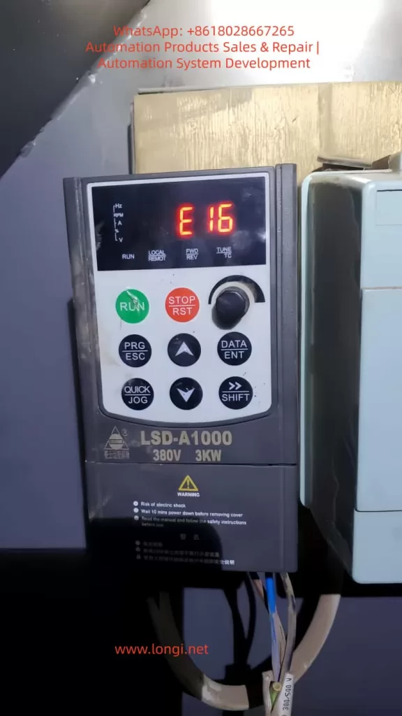
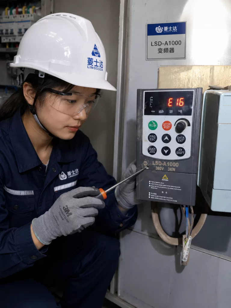
According to the Lingshida LSD-A1000 inverter manual, the E16 fault code is defined as “Communication Error”. Typical symptoms include:
- The inverter’s operation panel displays “E16” and cannot start the motor via the RUN key;
- The host computer (e.g., PLC) fails to read the inverter’s operating parameters (e.g., frequency, current, voltage);
- The host computer cannot send control commands (e.g., start, stop, frequency adjustment) to the inverter;
- The communication indicator lights (e.g., RX/TX) between the inverter and the host computer do not flash or flash abnormally.
2.2 Impact of the Fault
The E16 fault disrupts production workflows. If not resolved promptly, it may trigger secondary issues such as:
- Motor shutdowns, leading to production downtime and increased operational costs;
- Inability to monitor motor operating status in real time, potentially causing overloads, overheating, or other faults;
- Interruption of data transmission, affecting the statistics and analysis of production data (e.g., energy consumption, output).
3. Root Cause Analysis of E16 Fault
Based on the fault manual and on-site maintenance experience, the core causes of the E16 fault can be categorized into three major groups: abnormal host computer operation, communication cable faults, and incorrect communication parameter settings. A detailed analysis of each category is provided below.
3.1 Abnormal Host Computer Operation
The host computer (e.g., PLC, industrial PC) acts as the “initiator” of communication with the inverter. Its operating status directly affects communication stability. Common host computer abnormalities include:
3.1.1 Power Supply Issues
- Unstable power voltage: The host computer’s power voltage must remain stable within the rated range (e.g., AC 220V ± 10%). Excessive voltage fluctuations (e.g., beyond ± 15%) can cause the host computer’s communication interface (e.g., RS485 interface) to malfunction, preventing signal transmission or reception;
- Incorrect power wiring: Reversing or failing to ground the host computer’s live (L), neutral (N), and earth (PE) wires can damage the interface circuit, leading to communication interruptions.
3.1.2 Software Faults
- Communication software not running: If the host computer’s communication software (e.g., SCADA, PLC programming software) is not launched or crashes, a connection with the inverter cannot be established;
- Incorrect software parameter configuration: Mismatched communication parameters (e.g., baud rate, data bits, stop bits) between the host computer software and the inverter result in incompatible data formats, making signal parsing impossible;
- Software conflicts: Running multiple communication software programs (e.g., Modbus and Profibus protocols) simultaneously on the host computer occupies interface resources, causing communication errors.
3.1.3 Interface Damage
- Physical interface damage: Bent, oxidized, or burnt pins on the host computer’s RS485 interface interrupt signal transmission;
- Interface driver circuit damage: Overvoltage or overcurrent can damage the host computer’s RS485 driver chip (e.g., MAX485), preventing the conversion of TTL signals to RS485 differential signals.
3.2 Communication Cable Faults
Communication cables serve as the “signal channel” between the inverter and the host computer. Their connection status directly impacts communication quality. Common cable faults include:
3.2.1 Incorrect Wiring
- Reversed A/B wires: RS485 communication uses differential signal transmission. The A wire (positive signal) and B wire (negative signal) must be connected correspondingly (inverter’s A to host computer’s A, inverter’s B to host computer’s B). Reversing them causes signal polarity mismatches, making it impossible for the inverter to recognize host computer commands;
- Unshielded cables: The shielding layer of RS485 communication cables must be grounded at one end (usually the inverter’s PE terminal). Failing to ground the shielding layer allows external electromagnetic interference (e.g., high-frequency noise from motor startup) to enter the cable, causing signal errors;
- Loose connections: Loose wiring terminals (e.g., inverter’s TXD/RXD terminals, host computer’s RS485 terminals) result in poor contact and signal interruptions.
3.2.2 Cable Damage
- Broken wires: Pulling, squeezing, or rodent damage can break the internal conductors of the communication cable, interrupting signal transmission;
- Short circuits: Shorting the A/B wires of the communication cable to power lines (e.g., AC 220V) or earth wires shorts the signal, preventing it from reaching the inverter;
- Insulation aging: The insulation layer of the communication cable ages and cracks after long-term use (e.g., over 5 years), causing signal leakage and degraded communication quality.
3.3 Incorrect Communication Parameter Settings
Communication parameters are the “language rules” between the inverter and the host computer. Mismatched parameters prevent the two devices from “communicating.” The Lingshida LSD-A1000 inverter’s communication parameters are primarily stored in the P0 group (parameter numbers P0.00 to P0.15). Common parameter errors include:
3.3.1 Incorrect Communication Address
- Mismatched inverter and host computer addresses: The inverter’s communication address (P0.01) must match the slave address set in the host computer software (e.g., if the inverter is set to 1, the host computer must also be set to 1). A mismatch prevents the host computer from identifying the inverter, causing communication interruptions;
- Address conflicts: When multiple inverters are connected to the same host computer, duplicate addresses (e.g., two inverters both set to 1) cause communication conflicts, triggering the E16 fault.
3.3.2 Baud Rate Errors
- Mismatched baud rates: The baud rate (P0.02) is the data transmission rate of the communication parties (e.g., 9600, 19200, 115200 bps) and must be identical. If the inverter is set to 9600 and the host computer to 19200, data bit synchronization fails, making signal parsing impossible;
- Baud rate out of range: The Lingshida LSD-A1000 inverter supports a baud rate range of 1200 to 115200 bps. Setting a baud rate beyond this range (e.g., 230400 bps) renders the communication module inoperable.
3.3.3 Errors in Data Bits, Stop Bits, and Parity Bits
- Mismatched data bits: The number of binary bits per character (data bits, P0.03) must match between the inverter and the host computer (e.g., 7 bits or 8 bits). A mismatch (e.g., inverter set to 7 bits, host computer to 8 bits) causes character parsing errors;
- Mismatched stop bits: The number of idle bits after character transmission (stop bits, P0.04) must be consistent (e.g., 1 bit or 2 bits). A mismatch (e.g., inverter set to 1 bit, host computer to 2 bits) causes character boundary recognition errors;
- Incorrect parity bits: Parity bits (P0.05) are used to detect data transmission errors (e.g., no parity, odd parity, even parity). A mismatch (e.g., inverter set to even parity, host computer to odd parity) causes parity check failures, leading to communication interruptions.
4. Troubleshooting Steps and Case Verification for E16 Fault
4.1 Troubleshooting Steps
Troubleshooting the E16 fault should follow the principle of “from simple to complex, from external to internal,” checking the host computer, communication cables, and parameter settings in sequence. Specific steps are as follows:
Step 1: Check Host Computer Operation Status
Objective: Confirm whether the host computer can normally send/receive communication signals.
Procedure:
- Check power supply: Use a multimeter to measure the host computer’s power voltage (AC 220V) and ensure it is stable within the rated range (± 10%); check if the power wiring (L, N, PE) is correct and the earth wire is grounded (grounding resistance ≤ 4Ω).
- Check software: Confirm that the host computer’s communication software (e.g., KingView, STEP 7) is running and that the software’s communication parameters (baud rate, data bits, stop bits, parity) match the inverter; close unnecessary software (e.g., antivirus, office software) to avoid resource occupation.
- Check interface: Observe the host computer’s RS485 interface indicator lights (e.g., RXD, TXD). If the lights do not turn on, use a multimeter to measure the interface’s power voltage (e.g., DC 5V) to confirm if the interface circuit is normal; replace the RS485 interface module if the interface is damaged.
Step 2: Check Communication Cable Connection Status
Objective: Confirm whether the communication cable can normally transmit signals.
Procedure:
- Power off inspection: Turn off the power to the inverter and host computer to avoid electric shock;
- Check wiring: Refer to the inverter’s wiring diagram (e.g., Figure 1) to confirm correct connection of the communication cable’s A/B wires (inverter’s TXD to host computer’s RXD, inverter’s RXD to host computer’s TXD); check if the shielding layer is grounded at one end (connected to the inverter’s PE terminal); tighten the wiring terminals to avoid looseness.
- Test cable continuity: Use a multimeter’s continuity mode to measure the A/B wires of the communication cable (inverter side and host computer side) and confirm there are no broken wires; use a megohmmeter to measure the insulation resistance between the A/B wires and power/earth wires (≥ 1MΩ) to confirm no short circuits.
- Replace communication cable: If the cable is damaged (e.g., broken wires, aged insulation), replace it with a new RS485 shielded cable of the same specification (e.g., 2×1.5mm² shielded wire).
Step 3: Check and Correct Communication Parameter Settings
Objective: Ensure the inverter’s communication parameters match the host computer.
Procedure:
- Read inverter parameters: Read the P0 group parameters (e.g., Table 1) via the inverter’s operation panel or use the inverter’s dedicated software (e.g., LSD-Config) to connect to the inverter and read parameters;
- Compare host computer parameters: Contrast the inverter’s parameters with those set in the host computer software to identify inconsistencies;
- Modify parameters: Adjust the inverter’s parameters via the operation panel (steps below) or use dedicated software to modify and download parameters to the inverter:
- Press the “PRG” key to enter parameter setting mode;
- Use the “↑/↓” keys to select P0 group parameters (e.g., P0.01);
- Press the “DATA/ENT” key to enter the parameter modification interface;
- Use the “↑/↓” keys to adjust the parameter value and the “SHIFT” key to switch parameter bits;
- Press the “DATA/ENT” key to save the parameter and the “ESC” key to exit.
4.2 Case Verification
Case Background: An LSD-A1000-3KW inverter (controlling a textile machine motor) in a textile factory experienced an E16 fault, causing the textile machine to shut down and affecting production.
Troubleshooting Process:
- Check host computer: The host computer (industrial PC) had a stable power voltage (AC 220V), the communication software (KingView) was running, and the software parameters (baud rate 9600, data bits 8, stop bits 1, even parity) matched the inverter manual; the interface indicator lights (RXD, TXD) flashed normally, so the host computer was initially deemed normal.
- Check communication cable: After powering off, the wiring was inspected, and it was found that the inverter’s TXD (A wire) was connected to the host computer’s RXD (B wire), and the inverter’s RXD (B wire) was connected to the host computer’s TXD (A wire)—A/B wires were reversed. After re-wiring, the E16 fault persisted when power was restored.
- Check parameter settings: The inverter’s P0 group parameters were read via the operation panel, and it was found that P0.02 (baud rate) was set to 9600, while the host computer software’s baud rate was set to 19200—baud rate mismatch. After changing the inverter’s P0.02 to 19200 and saving the parameters, the E16 fault was resolved, and communication between the inverter and the host computer returned to normal.
5. Preventive Measures and Maintenance Suggestions for E16 Fault
To prevent the occurrence of the E16 fault, regular maintenance of the inverter’s communication system is essential. Specific measures are as follows:
5.1 Regular Inspection of Communication Cable Connections
- Monthly inspection: Check the connection status of the communication cable once a month to ensure correct A/B wire connection, proper grounding of the shielding layer, and no loose wiring terminals;
- Quarterly testing: Use a multimeter to measure the continuity and insulation resistance of the communication cable every quarter to ensure no damage;
- Annual replacement: If the communication cable has been in use for more than 3 years, replace it with a new RS485 shielded cable to avoid insulation aging-related faults.
5.2 Regular Verification of Communication Parameters
- Parameter backup: Back up the P0 group communication parameters (e.g., export via dedicated software) during initial inverter debugging to avoid parameter loss;
- Semi-annual核对: Check the communication parameters (baud rate, data bits, stop bits, parity, address) between the inverter and the host computer every six months to ensure consistency;
- Modification records: Record the time, operator, and content of any parameter modifications to avoid accidental misoperations.
5.3 Maintain Stable Host Computer Operation
- Weekly reboots: Reboot the host computer weekly to clear software cache and avoid software conflicts;
- Software updates: Promptly update the host computer’s communication software (e.g., KingView patches) to fix software vulnerabilities;
- Avoid overloading: Install the host computer in a well-ventilated environment to prevent hardware damage due to high temperatures; do not run unrelated software (e.g., games, videos) on the host computer to avoid CPU overloading.
5.4 Establish a Fault Log
- Record faults: Document the occurrence time, symptoms, troubleshooting process, and solution for E16 faults to establish a fault log;
- Trend analysis: Regularly analyze the fault log to identify high-frequency causes (e.g., reversed A/B wires, incorrect baud rate settings) and develop targeted preventive measures;
- Employee training: Train operators on the common causes and simple troubleshooting methods of the E16 fault (e.g., checking wiring, restarting the inverter) to reduce downtime.
6. Conclusion
The E16 communication abnormality fault of the Lingshida LSD-A1000 inverter is essentially an interruption in signal transmission between the inverter and the host computer. Its core causes include abnormal host computer operation, communication cable faults, and incorrect communication parameter settings. The key to resolving this fault lies in comprehensive troubleshooting, narrowing down the fault range step by step from the host computer to the communication cable and then to parameter settings. Through the case verification and step-by-step guidance in this article, on-site maintenance personnel can quickly locate the root cause of the E16 fault and take effective solutions.
Furthermore, preventing the occurrence of the E16 fault is even more critical. By regularly inspecting communication cable connections, verifying parameters, maintaining stable host computer operation, and establishing a fault log, the incidence of the E16 fault can be effectively reduced, improving production efficiency. In industrial automation production, the communication stability of inverters directly affects the continuity of production processes. Therefore, it is essential to attach importance to the maintenance and management of the communication system to ensure unimpeded “dialogue” between the inverter and the host computer.
Appendix: P0 Group Communication Parameter Table for Lingshida LSD-A1000 Inverter
| Parameter No. | Parameter Name | Value Range | Default Value | Description |
|---|---|---|---|---|
| P0.01 | Communication Address | 1~247 | 1 | Slave address of the inverter |
| P0.02 | Baud Rate | 1200~115200 bps | 9600 | Data transmission rate |
| P0.03 | Data Bits | 7~8 | 8 | Binary bits per character |
| P0.04 | Stop Bits | 1~2 | 1 | Idle bits after character transmission |
| P0.05 | Parity Bit | 0~2 | 0 | 0=No parity, 1=Odd parity, 2=Even parity |
| P0.06 | Communication Mode | 0~3 | 0 | 0=Modbus RTU, 1=Profibus DP |
| P0.07 | Timeout Time | 0~65535 ms | 100 | Communication timeout (ms) |