
In industrial automation systems, analog outputs from inverters are widely used to transmit operating frequency, output current, output voltage, torque, power, and other real-time operating data to PLCs, HMIs, recorders, or supervisory systems. Although this appears to be a simple analog wiring task, field commissioning often reveals problems such as:
“The parameter has already been set correctly, but the PLC display is still inaccurate.”
A typical example involves a JT330S2 inverter configured to output a 0–20mA analog signal through terminal AO2 so that a Siemens S7-200 SMART PLC can monitor the motor’s actual running current. According to the inverter manual, the technician sets parameter:
F6-08 = 2
which selects “Output Current” as the AO2 output function.
However, during operation, the inverter display or clamp meter shows an actual motor current of approximately 20A, while the PLC displays only 10A — exactly half of the real value.
This type of issue should not immediately be interpreted as:
“The inverter is faulty”
or
“The parameter was set incorrectly.”
From a troubleshooting perspective, the problem is usually related to scaling mismatch between:
1. What signal the inverter actually outputs
2. What signal the PLC actually receives
3. How the PLC program converts that signal into engineering units
To solve the problem correctly, all three stages must be analyzed independently.
1. Basic Function of AO2 Analog Output
The JT330S2 inverter provides two analog outputs:
AO1
AO2
These outputs can be configured to represent different operating parameters, including:
Running frequency
Set frequency
Output current
Output torque
Output power
Output voltage
Input analog values
Motor speed
Communication settings
In this application, the user wants the PLC to monitor the motor output current, therefore AO2 should be configured as:
F6-08 = 2
meaning:
AO2 output function = Output Current
This setting direction is correct. However, F6-08 only determines:
“What AO2 outputs”
It does NOT automatically guarantee:
“20A motor current = 20mA analog output”
Analog output accuracy also depends on:
Output mode
Zero offset
Gain
Full-scale mapping
PLC input scaling
Engineering unit conversion
Therefore, F6-08 is only the first step. The technician must still verify:
Whether AO2 is configured as current or voltage output
Whether AO2 outputs 0–20mA or 4–20mA
How the PLC analog module is configured
How the PLC program converts the raw analog value
2. Why the PLC Displays Only Half the Actual Current
The key field symptom is:
Actual motor current: 20A
PLC displayed current: 10A
An error that is exactly “half” is usually not random. It almost always indicates a scaling mismatch.
Suppose the inverter internally defines:
20mA = 40A
Then when the motor current is 20A, AO2 only needs to output half-scale current:
Approximately 10mA
Now suppose the PLC program assumes:
20mA = 20A
Then the PLC interprets 10mA as:
10A
This creates the observed condition:
Actual 20A
→ AO2 outputs approximately 10mA
→ PLC interprets 10mA as 10A
Therefore, the issue is most likely NOT that AO2 is malfunctioning. Instead, the scaling relationship between the inverter analog output and the PLC engineering conversion is inconsistent.

3. Measure the Actual AO2 Output Current First
One of the biggest mistakes in field troubleshooting is immediately changing parameters without measurement.
The correct approach is to first measure the real AO2 output current using a multimeter.
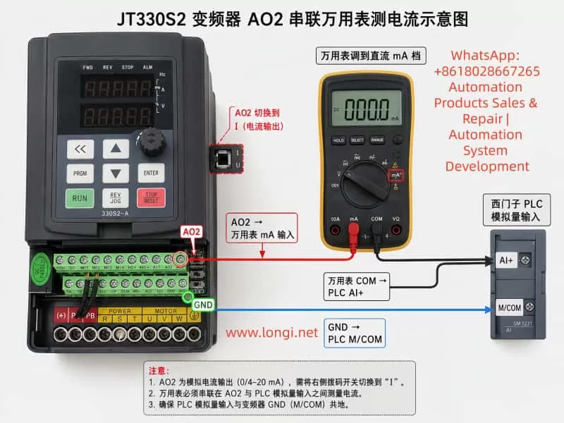
Unlike voltage measurement, current measurement must be performed in series.
The correct wiring method is:
Inverter AO2 → Multimeter mA Input
Multimeter COM → PLC Analog Input AI+
Inverter GND → PLC Analog M/COM
In practical terms:
Disconnect the wire between AO2 and PLC AI+
Insert the multimeter in series
The multimeter must be set to:
DC mA measurement mode
The red probe must be inserted into the:
mA terminal
and the black probe into:
COM
If the meter is accidentally placed in voltage mode, AC current mode, or connected in parallel, the reading will be incorrect and the meter fuse may even blow.
4. Using Measured Values to Determine the Root Cause
During testing, record three values simultaneously:
1. Inverter displayed output current
2. Multimeter measured AO2 current signal
3. PLC displayed current
Measurements should be taken at multiple load points:
Low load (e.g. 5A)
Medium load (e.g. 10A)
High load (e.g. 20A)
Case 1: Actual 20A → AO2 ≈ 10mA → PLC Displays 10A
This means the PLC display follows the analog signal correctly, but the engineering scaling range is too small.
The PLC likely assumes:
20mA = 20A
while the inverter output behaves like:
20mA = 40A
Typical PLC conversion formula:
Current = Raw_AI × 20 / 27648
should instead become:
Current = Raw_AI × 40 / 27648
This adjustment causes:
10mA → 20A
which restores correct display.
Case 2: Actual 20A → AO2 ≈ 20mA → PLC Displays 10A
In this case, the inverter analog output is already correct.
The fault is entirely on the PLC side.
Possible causes include:
Incorrect analog module range
Incorrect PLC scaling formula
Incorrect HMI engineering scaling
Additional divide-by-two logic in the program
Incorrect analog module configuration
If the PLC raw analog value already reaches near full scale but the displayed engineering value is still half, the inverter is NOT the problem.
Case 3: Actual 20A → AO2 Has Almost No Current Output
This suggests a hardware or wiring issue.
The technician should verify:
AO2 jumper/switch position
AO2 wiring
PLC analog input type
GND common reference
F6-08 parameter
F6-12 offset
F6-13 gain
On the JT330S2 control board, AO1 and AO2 can be configured as either:
Voltage output (V)
Current output (I)
If AO2 is still configured for voltage output while the PLC expects current input, readings will be abnormal.
5. Recommended Inverter Parameter Settings
For transmitting actual motor current through AO2:
AO2 Hardware Mode
Set AO2 jumper/switch to:
I = Current Output
Do NOT leave it at:
V = Voltage Output
AO2 Function Selection
F6-08 = 2
meaning:
AO2 outputs motor current
AO2 Offset
F6-12 = 0.0%
Normally keep default.
Improper offset adjustment can create false low-current readings.
AO2 Gain
F6-13 = 1.00
Normally keep default initially.
If measurements confirm the AO2 signal is exactly half the desired value, gain can be increased:
F6-13 = 2.00
However, increasing gain also risks premature saturation.
Example:
Originally:
40A = 20mA
After doubling gain:
20A = 20mA
Then any current above 20A can no longer be represented properly.
Therefore, adjusting PLC scaling is usually preferable.
6. PLC Engineering Unit Scaling Is Often Overlooked
Siemens S7-200 SMART analog modules typically convert analog current into digital values.
A common full-scale raw value is:
27648
for:
0–20mA
Engineering conversion formula:
Engineering_Value = Raw_AI × FullScale / 27648
The key question is:
What actual current does 20mA represent?
The PLC does not know automatically.
The programmer must define it.
If the PLC program assumes:
20mA = 20A
then:
10mA = 10A
If the inverter behavior is actually:
20mA = 40A
then the PLC formula must be updated accordingly.
7. 0–20mA and 4–20mA Must Not Be Confused
Industrial analog current signals are commonly:
0–20mA
4–20mA
0–20mA:
0mA = zero signal
20mA = full scale
4–20mA:
4mA = zero signal
20mA = full scale
4–20mA allows wire-break detection because signal loss drops below 4mA.
The following three elements must always match:
Inverter output type
PLC analog input type
PLC scaling formula
If one side uses 0–20mA and the other assumes 4–20mA, scaling errors will occur.
8. Why Special Output Modes Should Not Be Used Randomly
Some JT330S2 firmware versions include special AO2 scaling options such as:
100% = 1000A
These modes are usually intended for:
Special scaling
Communication mapping
Large-current systems
Manufacturer calibration
They are generally unsuitable for standard motor current monitoring applications.
For normal PLC monitoring:
F6-08 = 2
is the preferred choice.
Scaling corrections should then be handled through:
F6-13 gain adjustment
or
PLC engineering scaling
9. Recommended Field Commissioning Procedure
A practical troubleshooting workflow:
Step 1 — Verify Wiring
AO2 → PLC AI+
GND → PLC M/COM
For testing:
AO2 → Multimeter mA input
Multimeter COM → PLC AI+
GND → PLC M/COM
Step 2 — Verify AO2 Hardware Mode
AO2 jumper = I
Step 3 — Verify Parameters
F6-08 = 2
F6-12 = 0.0%
F6-13 = 1.00
Step 4 — Record Operating Data
Measure:
Actual motor current
AO2 mA signal
PLC raw analog value
PLC displayed engineering value
Step 5 — Analyze Results
Correct AO2 but wrong PLC display
→ PLC scaling issue

AO2 signal too small
→ Gain or scaling mismatch

No AO2 signal
→ Wiring/jumper/input mode issue

Unstable signal
→ Grounding/shielding/noise problem
10. Wiring and Safety Considerations
Even though AO2 is a low-level control signal, inverter commissioning still involves dangerous power circuits.
Important precautions:
Never modify power wiring while energized
Do not short 24V, 10V, or GND terminals
Current measurement must be series-connected
Use correct meter terminals
Avoid shorting AO2 to GND
Ensure proper common grounding
Use shielded analog cables
Separate analog cables from motor cables
Many analog signal issues are actually caused by:
Improper shielding
Noise interference
Incorrect grounding
Mixed routing with motor cables
Floating analog commons
rather than parameter settings.
11. Explaining the Problem to Customers
A practical explanation for customers is:
“Setting F6-08=2 only tells the inverter to output motor current through AO2. The PLC display depends on how many milliamps AO2 actually outputs and how the PLC converts those milliamps into amps. If actual current is 20A but PLC shows 10A, the scaling ratio is incorrect. First measure the real AO2 output current with a multimeter. If 20A corresponds to 10mA, either adjust PLC scaling so that 20mA equals 40A, or increase AO2 gain. If 20A already corresponds to 20mA, then the issue is entirely inside the PLC program.”
This explanation helps avoid unnecessary inverter replacement.
12. Conclusion
When using the JT330S2 inverter AO2 analog output to transmit motor current to a Siemens PLC, parameter:
F6-08 = 2
is correct, but it is only the function selection step.
The common field symptom:
Actual 20A
PLC displays 10A
is usually caused by mismatch between:
AO2 output scaling
PLC analog input scaling
Engineering conversion formulas
The proper diagnostic method is to:
Measure the real AO2 mA signal first
using a multimeter connected in series.
Then determine whether the issue lies in:
PLC scaling
AO2 gain
Wiring
Output mode
Grounding
In most practical applications, correcting PLC engineering scaling is preferable to increasing AO2 gain, because it avoids premature analog output saturation and preserves full measurement range.
The key principle in troubleshooting analog output systems is understanding the complete signal chain:
Motor Current
→ Inverter Internal Calculation
→ AO2 Analog Output
→ PLC Analog Acquisition
→ PLC Engineering Conversion
→ HMI Display
By testing and verifying each stage independently, technicians can rapidly locate the true cause of scaling errors and avoid unnecessary hardware replacement or repeated blind parameter adjustments.