
Introduction
Online oxygen analyzers are widely used in pharmaceutical water systems, chemical processes, power plants, fermentation systems, inert gas protection, combustion control, metallurgical processes, environmental monitoring, and industrial gas production. In many of these applications, dissolved oxygen or gaseous oxygen concentration is a critical process variable. Incorrect oxygen measurement can lead to poor product quality, unsafe operating conditions, increased corrosion risk, excessive energy consumption, unstable combustion, or unreliable process control.
Electrochemical oxygen sensors remain common because they are relatively economical, sensitive, and suitable for continuous online measurement. However, these sensors require periodic calibration and maintenance. One of the most common calibration-related alarms is:
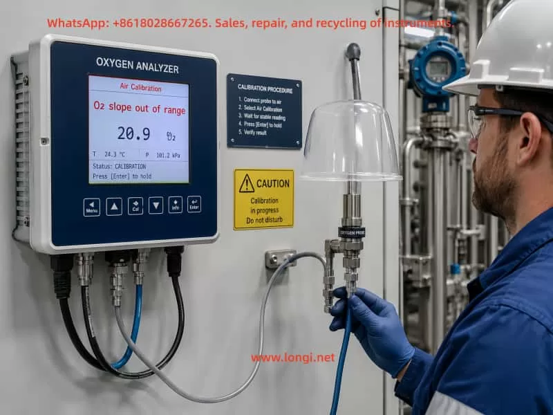
Slope Out of Range
On some Mettler Toledo M400 oxygen analyzer systems, the alarm may appear together with an abnormal slope value, such as:
O2 slope -2000 mV
This condition often occurs after an air calibration attempt. The analyzer may display an oxygen value close to zero, fail to complete calibration, or continue operating with an alarm active.
This article explains the technical meaning of the slope alarm, the electrochemical principle behind the measurement, the likely causes, the correct calibration conditions, and a practical field troubleshooting procedure.
1. What Does “Slope Out of Range” Mean?
The slope value represents the sensitivity of the oxygen sensor.
During calibration, the analyzer compares the sensor signal at a known oxygen condition with the expected oxygen value. For example, during air calibration, the sensor is exposed to atmospheric air containing approximately 20.9% oxygen. The analyzer measures the sensor response and calculates whether the sensor sensitivity is still within the acceptable range.
If the calculated sensor sensitivity is too high, too low, unstable, negative, or otherwise outside the configured acceptable limits, the analyzer generates a:
Slope Out of Range Alarm
In practical terms, this means:
The analyzer cannot establish a valid relationship between the actual oxygen concentration and the electrical signal generated by the sensor.
The alarm is therefore not simply a display issue. It indicates that either the sensor, calibration condition, signal connection, or stored calibration data is abnormal.
2. The Technical Meaning of Sensor Slope
An oxygen analyzer does not directly detect ppm or percentage oxygen values. The sensor produces an electrical signal, usually a small current or voltage. The analyzer converts that electrical signal into an oxygen concentration using calibration parameters.
A simplified measurement relationship can be written as:
[
O_2 = k \times S + b
]
Where:
- (O_2) = oxygen concentration
- (S) = sensor electrical signal
- (k) = slope or sensitivity factor
- (b) = offset or zero-point compensation
The slope parameter determines how much the measured oxygen value changes when the sensor signal changes.
A healthy sensor should produce a stable and repeatable response under standard calibration conditions. If the sensor is aged, contaminated, damaged, dry, electrically unstable, or incorrectly calibrated, the slope value may become invalid.
An extreme slope value such as -2000 mV generally indicates that the analyzer has detected an abnormal sensor response or has failed to calculate a valid calibration factor.
3. Basic Operating Principle of Electrochemical Oxygen Sensors
Many industrial oxygen analyzers use electrochemical sensor technology. Depending on the design, the sensor may be a Clark-type polarographic sensor, galvanic oxygen sensor, or similar electrochemical system.
A typical electrochemical oxygen sensor contains:
- Cathode
- Anode
- Electrolyte
- Oxygen-permeable membrane
- Electrical connection system
- Temperature measurement element in some models
Oxygen molecules diffuse through the membrane and enter the electrolyte. A controlled electrochemical reaction occurs at the electrode surface. This reaction generates a signal proportional to the oxygen partial pressure or dissolved oxygen concentration.
A simplified oxygen reduction reaction is:
[
O_2 + 4e^- + 2H_2O \rightarrow 4OH^-
]
The generated current is measured by the analyzer. The analyzer then applies the calibration slope and offset values to calculate the oxygen concentration.
Because the membrane, electrolyte, electrodes, and internal chemistry all affect sensor response, the sensor is considered a consumable component. It cannot maintain perfect sensitivity indefinitely.
4. Why the Membrane Must Remain Installed During Calibration
A common misunderstanding is that the membrane should be removed during calibration. This is incorrect.
For electrochemical oxygen sensors, the membrane is part of the sensing system. It controls oxygen diffusion into the electrolyte and directly affects the sensor response. Removing the membrane changes the diffusion characteristics and exposes the internal electrode system to the environment.
Therefore:
- The membrane must remain installed during normal calibration.
- The membrane must be intact and properly fitted.
- The membrane must not be torn, loose, dry, wrinkled, contaminated, or leaking.
- The electrolyte condition must be suitable for normal sensor operation.
Calibration should always be performed with the complete sensor assembly in its normal measuring condition.
Removing the membrane during calibration can cause unstable readings, unrealistic sensitivity values, electrolyte contamination, and invalid calibration results.
5. Main Causes of Slope Out of Range Alarms
The causes can generally be divided into four groups:
- Sensor-related faults
- Calibration condition problems
- Electrical connection or signal-chain problems
- Analyzer configuration or stored-data problems
Each group should be checked systematically.
6. Sensor-Related Causes
6.1 Sensor Aging
Sensor aging is the most common reason for slope alarms.
Over time, the electrochemical reaction becomes less efficient. The electrode surface may deteriorate, the electrolyte may lose performance, and the membrane permeability may change. The sensor output gradually becomes weaker or less stable.
Typical signs of sensor aging include:
- Slow response time
- Calibration takes much longer than normal
- Repeated calibration failures
- Slope value gradually decreasing over time
- Unstable readings in air
- Oxygen value remains near zero or fluctuates abnormally
- The analyzer cannot accept a new calibration
When a sensor reaches the end of its useful life, calibration cannot restore normal performance. The sensor must be serviced or replaced.
6.2 Electrolyte Depletion or Contamination
The electrolyte is essential for the internal electrochemical reaction.
Possible electrolyte-related problems include:
- Electrolyte evaporation
- Electrolyte leakage
- Long-term storage without proper maintenance
- Contamination by process media
- Incorrect electrolyte type
- Air bubbles trapped inside the sensor
- Incorrect refill procedure
If the electrolyte has deteriorated, the electrical response of the sensor may become weak, noisy, delayed, or non-linear. This can result in an unacceptable slope value during calibration.
For sensors with replaceable electrolyte, the electrolyte should be replaced according to the manufacturer’s maintenance procedure. For sealed sensors, the complete sensor may need replacement.
6.3 Damaged or Contaminated Membrane
The membrane controls how oxygen enters the sensor. Even minor membrane damage can cause major calibration problems.
Common membrane issues include:
- Puncture or tear
- Scratches
- Wrinkles
- Improper tension
- Chemical attack
- Oil contamination
- Protein or biological fouling
- Mineral deposits
- Dry or brittle membrane
- Membrane cap not tightened correctly
A damaged membrane may allow oxygen to diffuse too quickly, too slowly, or inconsistently. This creates unstable sensor output and can produce a slope alarm.
A contaminated membrane can also reduce oxygen diffusion. The analyzer may then interpret the weak response as sensor degradation.
6.4 Electrode Contamination or Chemical Poisoning
Certain process environments can poison or contaminate the electrode system. Sulfur-containing gases, aggressive chemicals, oil vapor, solvents, chlorine compounds, or biological contamination may affect sensor performance.
Possible symptoms include:
- Sudden slope reduction
- Very slow response
- Failure after exposure to a specific process gas
- Temporary recovery after cleaning, followed by repeated failure
- Calibration success in clean air but unstable measurement in process conditions
In such cases, the process medium, sensor installation location, sample conditioning system, and maintenance interval should all be reviewed.
6.5 Sensor Dry-Out During Storage or Shutdown
Some oxygen sensors require proper storage conditions. If a sensor is stored dry or left out of service for a long period, the electrolyte system may become unstable.
Possible results include:
- Delayed sensor polarization
- Low sensitivity
- High baseline drift
- Failed calibration
- Slope out of range alarm
A sensor that has been stored incorrectly may require reconditioning, electrolyte replacement, membrane replacement, or complete replacement depending on the sensor design.
7. Calibration Condition Problems
Not every slope alarm means the sensor is defective. Incorrect calibration conditions can also produce an invalid slope value.
7.1 Unstable Air Flow
Air calibration requires stable exposure to atmospheric oxygen.
Common field mistakes include:
- Blowing air directly onto the sensor by mouth
- Using an unstable compressed-air source
- Holding the sensor in moving air
- Using an air calibration hood with leaks
- Rapidly moving the sensor during calibration
- Using a temporary enclosure with fluctuating humidity
A fast or irregular air stream can create unstable oxygen diffusion across the membrane. The sensor signal may fluctuate and the analyzer may reject the calibration.
The best approach is to use a proper calibration cap, calibration chamber, or stable reference gas arrangement recommended by the sensor manufacturer.
7.2 Insufficient Stabilization Time
The sensor must reach a stable signal before calibration is accepted.
If calibration is confirmed too early, the analyzer may calculate the slope from an unstable signal. This can produce false calibration failure or an abnormal slope.
The stabilization time depends on:
- Sensor type
- Previous oxygen level
- Temperature
- Membrane condition
- Process pressure
- Sensor age
- Electrolyte condition
- Air flow condition
A sensor recently removed from a low-oxygen process may need several minutes or longer to stabilize in air.
7.3 Incorrect Temperature Conditions
Oxygen sensor response is temperature-dependent. Most analyzers include temperature compensation, but calibration should still be performed under stable temperature conditions.
Problems may occur when:
- The sensor temperature is changing rapidly
- The sensor is removed from a hot process and immediately calibrated in cool air
- The temperature element is faulty
- The sensor is exposed to direct sunlight or heater radiation
- The calibration gas temperature differs significantly from the process condition
A stable ambient temperature is preferred. For general field calibration, a stable environment around 20–25°C is often suitable, but the correct procedure should follow the sensor manufacturer’s requirements.
7.4 Incorrect Pressure Compensation
Oxygen partial pressure depends on atmospheric pressure. For gas-phase oxygen measurement, pressure compensation may significantly influence calibration accuracy.
Potential issues include:
- Incorrect barometric pressure setting
- Calibration performed under vacuum or elevated pressure
- Instrument pressure compensation disabled
- Incorrect process pressure input
- Blocked pressure sensor line in sample systems
If pressure data are wrong, the analyzer may calculate an incorrect expected oxygen value and reject the calibration.
7.5 Moisture and Humidity Effects
Air contains water vapor, and humidity can affect oxygen partial pressure. In some applications, calibration gas moisture must be controlled.
Potential problems include:
- Condensation on the membrane
- High humidity causing slow stabilization
- Water droplets on the sensor
- Wet calibration cap
- Dry gas calibration used for a wet process without compensation
The membrane surface should be clean and free from liquid water droplets unless the calibration procedure specifically requires wet conditions.
8. Electrical Connection and Signal-Chain Problems
If the sensor itself appears physically normal, the next step is to inspect the electrical signal path.
8.1 Loose or Oxidized Connector
Sensor connectors may become oxidized, loose, contaminated, or damaged due to humidity, vibration, chemicals, or repeated plugging and unplugging.
Possible symptoms include:
- Intermittent readings
- Sudden jumps in oxygen value
- Calibration starts but fails randomly
- Slope value changes dramatically between attempts
- Analyzer reports sensor communication or diagnostic warnings
The connector should be inspected for:
- Corrosion
- Moisture
- Bent pins
- Loose locking ring
- Damaged sealing gasket
- Oil or chemical contamination
Always power down or follow the manufacturer’s connection procedure before disconnecting the sensor.
8.2 Damaged Cable or Shielding
A damaged sensor cable may introduce noise or cause intermittent open-circuit conditions.
Potential cable problems include:
- Broken conductor
- Crushed cable
- Rodent damage
- Water ingress
- Damaged shield
- Improper grounding
- Cable routed beside high-power inverter output cables
- Poor terminal connection
In industrial environments, oxygen sensor signals are often very small. Electromagnetic interference from variable frequency drives, contactors, heaters, welding equipment, or unshielded power cables may disturb the measurement.
The sensor cable should be routed away from high-voltage and high-current wiring. Shielding and grounding should follow the manufacturer’s wiring recommendations.
8.3 Analyzer Input Circuit Problems
Although less common than sensor failure, the analyzer input stage can also be defective.
Possible causes include:
- Internal analog input failure
- Moisture ingress
- Power supply instability
- Damaged sensor interface board
- Incorrect channel configuration
- Firmware or hardware fault
A useful troubleshooting method is to connect a known-good sensor to the analyzer. If the known-good sensor calibrates normally, the original sensor is likely defective. If the known-good sensor also fails, the analyzer or wiring system should be investigated.
9. Analyzer Configuration and Calibration Data Problems
9.1 Incorrect Sensor Type Selection
The analyzer must be configured for the correct sensor type and measurement range.
Possible configuration errors include:
- Wrong sensor technology selected
- Incorrect oxygen range
- Wrong calibration mode
- Wrong units
- Incorrect membrane or sensor parameter settings
- Incorrect temperature compensation setting
- Wrong process pressure configuration
If the analyzer configuration does not match the installed sensor, the slope calculation may be invalid.
9.2 Stored Calibration Data Corruption
In some cases, previous failed calibrations or incorrect parameter changes may leave invalid calibration data in memory.
Symptoms may include:
- Alarm remains active after a seemingly successful calibration
- Analyzer displays unrealistic slope values
- Calibration acceptance behavior is inconsistent
- Sensor value remains fixed after calibration
The corrective action may include:
- Resetting calibration data
- Restoring sensor calibration defaults
- Clearing invalid calibration history
- Reconfiguring the sensor channel
- Performing a complete zero and span calibration
The exact menu path depends on the analyzer version and sensor configuration.
9.3 Slope Acceptance Limits Set Too Narrow
Some systems allow the acceptable slope range to be configured. If the limits are set too narrow, a sensor that is still usable may be rejected.
However, slope limits should not be widened simply to remove the alarm. Doing so may hide a genuine sensor degradation issue and create inaccurate oxygen measurement.
Any change to acceptance limits should be based on:
- Manufacturer specifications
- Process quality requirements
- Sensor history
- Validation procedures
- Maintenance documentation
10. Practical Field Troubleshooting Procedure
The following sequence is suitable for a typical electrochemical oxygen analyzer showing a slope out of range alarm after air calibration.
Step 1: Confirm the Alarm Information
Record the following information before making changes:
- Analyzer model
- Sensor model
- Current oxygen reading
- Temperature reading
- Slope value
- Calibration date
- Previous successful calibration date
- Process conditions
- Sensor installation location
- Sensor age
- Membrane or electrolyte replacement history
A slope value such as -2000 mV should be treated as a significant abnormal condition, not as a minor calibration drift.
Step 2: Inspect the Sensor Physically
Check the sensor for:
- Membrane damage
- Membrane contamination
- Loose membrane cap
- Electrolyte leakage
- Dry sensor condition
- Cracks in the sensor body
- Moisture in electrical connector
- Corrosion at connector pins
- Damage caused by process chemicals
If the membrane is damaged or the electrolyte is contaminated, the sensor should be serviced before attempting another calibration.
Step 3: Confirm That the Membrane Is Installed
The membrane must remain installed during calibration.
Do not remove the membrane for air calibration.
The sensor should be calibrated in its normal operating configuration. If the membrane has been removed, replaced, or disturbed, the sensor may require reconditioning time before calibration.
Step 4: Allow the Sensor to Stabilize
Place the sensor in a stable calibration environment.
For air calibration:
- Use clean ambient air or approved calibration gas.
- Avoid blowing directly on the sensor.
- Avoid unstable compressed-air flow.
- Keep the sensor temperature stable.
- Allow enough time for the reading to stabilize.
- Do not confirm calibration until the analyzer indicates stability.
If the analyzer provides a stability indicator, wait until it meets the acceptance condition.
Step 5: Perform Calibration Again
Perform the correct calibration sequence according to the sensor type:
- Air calibration only, if applicable
- Zero calibration followed by air/span calibration
- Calibration with certified gas, if required by the process
- Calibration under controlled pressure and humidity conditions, if applicable
Do not repeatedly force calibration acceptance if the analyzer rejects the result. Repeated failed calibrations may overwrite useful diagnostic information.
Step 6: Check Electrical Connections
Inspect and test:
- Sensor plug
- Cable condition
- Connector locking
- Shielding
- Grounding
- Junction boxes
- Terminal blocks
- Cable routing near inverter or motor cables
Re-seat the connector and ensure it is fully locked. If possible, test the sensor with another compatible cable or analyzer input channel.
Step 7: Reset Invalid Calibration Data
If the sensor, membrane, electrolyte, calibration environment, and wiring all appear normal, reset the stored calibration data according to the analyzer service procedure.
Possible actions may include:
- Clear calibration data
- Restore calibration defaults
- Reset sensor calibration
- Delete failed calibration history
- Reconfigure the measurement channel
After the reset, repeat the complete calibration procedure under stable conditions.
Step 8: Test with a Known-Good Sensor
This is one of the most effective fault-isolation methods.
Connect a known-good compatible sensor to the same analyzer and cable.
Results can be interpreted as follows:
| Test Result | Likely Cause |
|---|---|
| Known-good sensor calibrates normally | Original sensor is defective or requires service |
| Known-good sensor also fails | Analyzer, cable, wiring, configuration, or calibration conditions are likely abnormal |
| Both sensors show unstable readings | Possible electrical noise, grounding, cable damage, or environmental instability |
| Original sensor works on another analyzer | Original analyzer channel may be defective |
11. Can the Alarm Be Cleared Manually?
In most systems, a slope alarm should not be treated as a simple message that can be manually erased.
The alarm is normally cleared only after the analyzer recognizes a valid sensor condition. This usually requires one of the following:
- Successful calibration
- Corrected sensor condition
- Repaired cable or connector
- Replacement of membrane or electrolyte
- Replacement of the sensor
- Reset and successful recalibration
- Correct analyzer configuration
Simply acknowledging or muting the alarm may silence the message temporarily, but it will not restore measurement accuracy.
The correct objective is not only to clear the alarm. The objective is to restore a valid and traceable oxygen measurement.
12. When Should the Sensor Be Replaced?
Sensor replacement should be considered when one or more of the following conditions are present:
- Calibration repeatedly fails under controlled conditions
- Slope remains outside the acceptable range after membrane and electrolyte service
- Signal remains unstable in clean air
- Sensor response is extremely slow
- Oxygen reading remains near zero in air
- Membrane and electrolyte condition are normal but slope remains abnormal
- Sensor has exceeded its expected service life
- Known-good sensor works normally on the same analyzer and cable
- The sensor has been exposed to damaging chemicals or extreme temperatures
In many practical cases, a persistent slope out of range alarm is the final indication that the electrochemical sensor has reached the end of its usable life.
13. Preventive Maintenance Recommendations
To reduce the occurrence of slope-related calibration failures, a preventive maintenance program should include the following items.
13.1 Routine Calibration
Perform calibration at a defined interval based on process criticality, sensor type, and regulatory requirements.
More frequent calibration may be needed in:
- High-temperature applications
- Dirty process media
- Chemical vapor environments
- Hygienic process systems
- Continuous critical control loops
- High humidity or condensate-prone locations
13.2 Membrane Inspection and Replacement
Inspect the membrane regularly for:
- Deposits
- Damage
- Loss of tension
- Cloudiness
- Chemical attack
- Leakage
Replace the membrane according to the maintenance schedule or whenever physical damage is found.
13.3 Electrolyte Maintenance
For refillable electrochemical sensors:
- Use only approved electrolyte.
- Avoid introducing air bubbles.
- Keep the sensor clean during service.
- Follow the specified filling volume.
- Allow adequate stabilization time after electrolyte replacement.
13.4 Cable and Connector Maintenance
Keep connectors dry and clean. Use proper strain relief. Inspect cable routing and avoid running sensor cables in parallel with inverter output cables or high-power conductors.
13.5 Maintain Calibration Records
Calibration history is valuable for predictive maintenance.
Record:
- Date and time
- Slope value
- Offset value
- Sensor temperature
- Calibration gas or air condition
- Sensor maintenance performed
- Membrane replacement date
- Electrolyte replacement date
- Process condition at the time of calibration
A gradual decline in slope can often predict sensor replacement before complete failure occurs.
14. Conclusion
A “Slope Out of Range” alarm on an electrochemical oxygen analyzer is a diagnostic warning that the analyzer cannot confirm valid sensor sensitivity during calibration.
The alarm may result from:
- Sensor aging
- Membrane damage
- Electrolyte depletion or contamination
- Electrode degradation
- Incorrect calibration conditions
- Insufficient stabilization time
- Temperature or pressure compensation errors
- Cable or connector problems
- Electrical noise
- Incorrect analyzer configuration
- Corrupted calibration data
In practical field service, the most common cause is sensor deterioration, especially membrane and electrolyte-related degradation. However, calibration conditions and electrical connections must be checked before replacing the sensor.
The membrane should remain installed during calibration because it is an essential part of the oxygen sensing system. Calibration must be performed with the sensor in its normal operating configuration and under stable, controlled conditions.
When a severe slope value such as -2000 mV remains after proper inspection, stable air calibration, wiring checks, and calibration reset, the sensor should be considered defective or at the end of its service life.