Posted on

MARPOSS TBD Laser Tool Breakage Detector Repair and Signal Testing: From Wiring Identification to Tool OK Output Diagnosis

1. Overview: The TBD Is Not a Conventional Laser Tool Setter

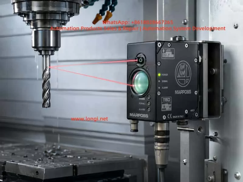
The MARPOSS TBD is a non-contact laser tool breakage detector used on CNC machining centers, drilling/tapping machines, and automated machine tools. At first glance, many technicians may mistake it for a normal laser tool setter. This leads to a common misunderstanding: as long as an object blocks the laser beam, the output should change immediately.

That is not how this device works.

The TBD is not primarily designed to measure tool length or automatically write tool offset values into the CNC system. Its core function is to check whether a tool is present, broken, or still suitable for machining. A more accurate description would be:

MARPOSS TBD laser tool breakage detector / non-contact tool presence detector.

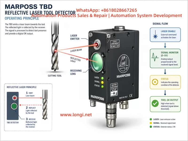
During operation, the CNC or PLC enables the TBD through an external input signal. The spindle moves the tool to a preset inspection position. The TBD emits a laser beam toward the tool surface. If the tool is intact, the laser is reflected back to the receiver lens. If the tool is broken, the expected reflective surface is missing, and the detector will classify the tool as broken or not identified.

Therefore, the TBD should not be treated as a simple through-beam or reflective photoelectric switch. It does not merely detect whether something blocks the laser beam. It must receive a valid reflected signal that matches its internal recognition logic. Only after the controller identifies a valid tool condition will the STATUS indicator turn on and the Tool OK output become active.

This distinction is crucial for repair work. If the technician only blocks the laser with a finger or metal plate and expects the output to change, the test result may be misleading.


MARPOSS TBD reflective laser tool breakage detector installed inside a CNC machine, emitting and receiving a red laser beam from a rotating cutting tool for non-contact tool presence detection.

2. External Structure and Key Components

A typical MARPOSS TBD unit has several important physical features.

The first is the large circular optical window on the front. This is mainly the receiving window. Reflected laser light from the tool surface enters through this lens and is detected by the internal optical receiver. Behind this window are typically the receiving optics, photodiode circuit, preamplifier, and signal conditioning circuits. If this window is cracked, fogged, contaminated, or filled with coolant residue, the detector may fail to identify the tool even when the laser emitter is working.

The second feature is the small laser emission aperture. The laser beam is emitted from this small opening and aimed toward the tool. The reflected light then returns to the large receiving lens. In many units, an air purge port is also provided near the optical area. The purpose of the air port is to keep coolant mist, oil, dust, and chips away from the optical surfaces.

The third feature is the multi-pin circular connector. This connector carries the power supply, Laser Enable input, Tool OK output, Signal Monitor analog output, and related common terminals. Different TBD versions and cable assemblies may use different wiring colors. Therefore, wiring should not be identified only by wire color. It must be confirmed by PCB tracing, component function, and actual testing.

The fourth feature is the front indicator panel. It usually has three indicators:

  • POWER
  • SIGNAL
  • STATUS

POWER indicates the power and laser enable state. SIGNAL indicates reflected signal strength. STATUS indicates whether the tool has been successfully identified. In troubleshooting, STATUS is the most important indicator for judging whether the Tool OK output should be active.

The fifth feature is the FOCUS POSITION adjustment. On some versions, this appears as a small adjustment mechanism marked with “FOCUS POSITION” and “FAR.” This is not a general operating mode selector. It is related to optical focus or detection distance. If the distance, angle, or focus setting is incorrect, the detector may show analog signal variation while the STATUS indicator remains off.


Technician testing an opened MARPOSS TBD laser tool breakage detector on a repair bench, measuring the PCB, signal wiring, laser enable input, signal monitor, and Tool OK output with a multimeter.

3. Identifying the Six Signal Wires

During repair, the unit may contain a separate pair of main power wires and a six-wire signal harness connected to the circular connector. By comparing a faulty unit with a known-good TBD, the six signal wires can be identified as follows:

Wire ColorProbable FunctionDescription
BlackSignal Monitor reference groundAnalog reference, not necessarily connected to main power 0V
RedSignal Monitor analog output0–5V analog monitor signal
YellowTool OK / COM OUT terminalOne side of PVT212S output
GreenTool OK / COM OUT terminalThe other side of PVT212S output
PinkLaser Enable inputExternal enable input
GrayCOM INCommon terminal for Laser Enable input

Several important points must be emphasized.

First, the black wire may connect to a local capacitor negative terminal or local signal reference node on the PCB, but it is not necessarily connected to the main power supply negative terminal. It should not be assumed to be the same as the device power 0V.

Second, the red wire is not the Laser Enable wire. PCB tracing shows that the red wire passes through a resistor and enters an AD823A signal conditioning stage. This strongly suggests that it belongs to an analog signal path, most likely the Signal Monitor output. Applying 12V or 24V to the red wire may damage the analog front end.

Third, the pink and gray wires form the Laser Enable input pair. In actual testing, applying an external 12V signal through a 4.7kΩ resistor to the pink wire, with the gray wire connected to 0V, caused the POWER indicator to change from green to orange and the laser to turn on. This confirms the pink/gray pair as the enable input.

Fourth, the yellow and green wires connect to the output side of a PVT212S PhotoMOS relay. They are not active voltage outputs. They behave like an isolated solid-state contact. An external power source and load are required to observe switching behavior.


Technical diagram explaining the MARPOSS TBD reflective laser tool detection principle, showing laser emission, reflected light reception, signal monitor output, status recognition, and Tool OK output flow.

4. The Role of the PVT212S PhotoMOS Relay

The PCB contains a PVT212S device. This component is not a simple optocoupler and not an analog amplifier. It is a PhotoMOS solid-state relay. Internally, it contains an input LED and an output MOSFET switch, optically isolated from each other.

In the TBD, the PVT212S is used as the final isolated Tool OK output stage.

Its working logic can be understood as follows:

The controller determines that a valid tool has been identified
↓
The controller drives the input LED of the PVT212S
↓
The PVT212S output MOSFET turns on
↓
The yellow and green wires form a closed solid-state switch
↓
The CNC / PLC receives the Tool OK signal

This explains why the yellow and green wires do not output 12V or 24V by themselves. They are equivalent to an isolated relay contact. Measuring yellow-to-ground or green-to-ground with a multimeter may show no meaningful voltage.

The correct way to test this output is to create an external low-current load circuit, for example:

+12V → 2.2kΩ or 4.7kΩ resistor → LED → Yellow wire
Green wire → 0V

If there is no response, reverse the yellow and green wiring and test again. In many PhotoMOS outputs, polarity may not matter for low-current DC tests, but both directions should still be verified.

However, the PVT212S output will only switch if its input side is driven. If pins 1 and 2 of the PVT212S always measure 0V, the yellow/green output will not change no matter how the external output circuit is connected.


5. Why Blocking the Laser Does Not Necessarily Activate the Output

A common mistake is to block the laser beam with a hand or metal plate and expect the Tool OK output to change. This is not a valid test for a TBD.

The TBD is based on reflected laser detection. It is not checking simple beam interruption. It is looking for reflected light from a tool surface under the correct geometric and optical conditions.

When a hand blocks the laser, the red/black Signal Monitor output may change significantly. For example, it may rise from about 0.6V to around 5V. This only proves that the receiver and analog signal chain respond to optical changes. It does not prove that the controller has recognized a valid tool.

A hand, flat metal plate, or random obstruction may create a saturated or invalid reflection. The internal logic may classify this as an invalid condition rather than a valid tool.

A more realistic test should use:

  • A drill bit
  • A tap
  • A shiny round steel rod
  • A screwdriver shaft
  • A cylindrical metal tool

The laser should strike the cylindrical surface or tool surface, not simply a flat plate. The best simulation is to rotate the tool or round bar slowly, because the real application typically involves rotating tools.

Only when the controller decides that the reflected signal corresponds to a valid tool will the STATUS indicator turn on. Only then should the PVT212S input and yellow/green output be expected to change.


6. Meaning of the POWER, SIGNAL, and STATUS Indicators

The three front indicators are essential for diagnosing the TBD.

POWER Indicator

The POWER indicator shows the power and laser enable state.

A typical operating sequence is:

  • Main power only: POWER should be green.
  • Laser Enable active: POWER should change to orange.
  • Fault state: POWER may show red or fail to remain on.

If the unit cannot hold a green POWER indicator with only main power applied, it has not entered normal standby. In that case, there is no point in expecting the yellow/green output to switch. The internal power supply, control logic, reset circuit, laser driver, or local regulators must be checked first.

SIGNAL Indicator

The SIGNAL indicator reflects the strength or quality of the received optical signal. It does not directly mean that the Tool OK output is active.

Signal Monitor voltage and the SIGNAL indicator are useful for aligning the optical path. However, signal variation alone does not guarantee that the tool has been identified.

STATUS Indicator

STATUS is the key indicator.

When STATUS turns on, the unit has identified the tool. When STATUS remains off, the tool is not identified or is considered broken. As long as STATUS is off, the PVT212S output may remain inactive. This is normal behavior.

If STATUS turns on but PVT212S pins 1 and 2 still remain at 0V, then the output drive circuit should be investigated.


7. The Red and Black Signal Monitor Wires

The red and black wires form the analog Signal Monitor output.

In testing, the voltage between red and black may vary from roughly 0V to 5V depending on the reflected signal. For example:

  • No valid reflection: around 0.6V
  • Strong obstruction or saturated reflection: near 5V

This signal is useful for optical alignment and signal evaluation. It is not a switching output and not a Laser Enable input.

The correct use of the Signal Monitor is:

  1. Apply the Laser Enable signal through the pink/gray pair.
  2. Measure DC voltage between the red and black wires.
  3. Move a drill bit or round rod in the laser path.
  4. Observe voltage changes.
  5. Use the voltage together with SIGNAL and STATUS indicators to find a valid detection position.

If red/black voltage changes but STATUS remains off, the receiver circuit is responding, but the signal is not being accepted as a valid tool identification condition.


8. The Importance of FOCUS POSITION Adjustment

The TBD is highly sensitive to distance, angle, and focus. The FOCUS POSITION adjustment is critical.

The unit may output laser light and show analog signal variation, but still fail to identify the tool if the focus is not correct. Typical symptoms include:

  • POWER changes from green to orange after Laser Enable.
  • The laser is visible.
  • Red/black Signal Monitor voltage changes.
  • SIGNAL may change.
  • STATUS remains off.
  • PVT212S is not driven.
  • Yellow/green output does not change.

This does not necessarily mean the electronics are faulty. It may simply mean the optical geometry is wrong.

A proper bench test should use a fixed setup. The TBD should be clamped securely. The test drill or round rod should also be fixed in a stable holder. Suggested starting distances are:

300mm → 500mm → 800mm

At each distance, slowly adjust:

  • Tool height
  • Tool angle
  • Lateral position
  • FOCUS POSITION
  • Tool rotation

The goal is to make STATUS turn on stably. If the technician holds the detector and tool by hand, the position may be too unstable, and STATUS may appear only briefly or not at all.


9. Function of the Air Port

The air port is often misunderstood. It is not usually an electrical interlock.

Its purpose is to provide air purge for the optical windows. It prevents coolant mist, oil vapor, dust, and chips from sticking to the transmitter aperture and receiver lens.

The air purge helps with:

  • Keeping the laser emission aperture clean
  • Keeping the receiver window clean
  • Reducing coolant interference
  • Improving long-term stability
  • Preventing false alarms in machine environments

For bench testing, air supply is generally not required to verify main power, Laser Enable, laser output, Signal Monitor, STATUS, and Tool OK output. However, for actual machine operation, clean and dry compressed air should be used. If the air contains oil or water, it may make the optical window dirtier rather than cleaner.


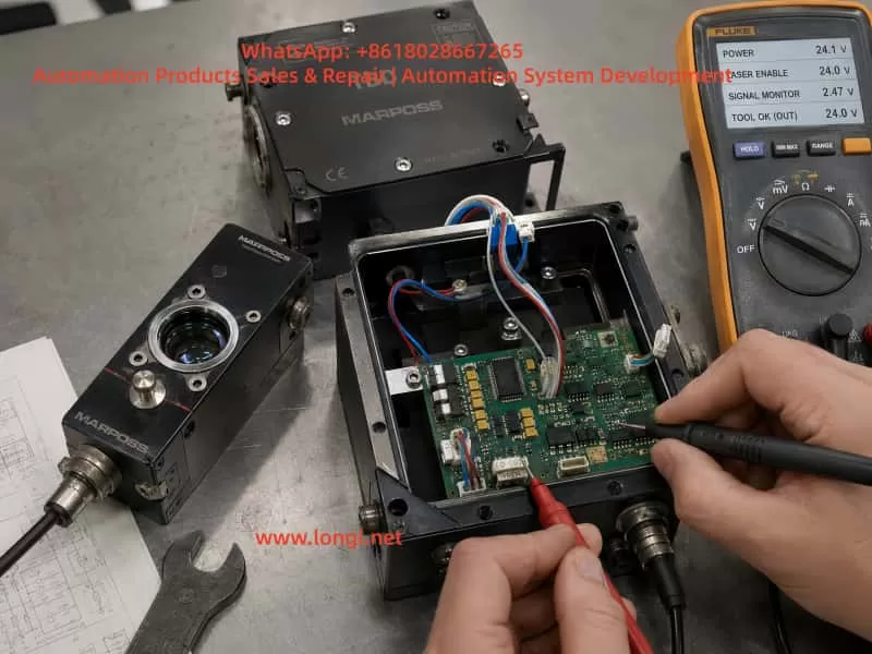
10. Complete Test Procedure Using a Known-Good Unit

The most efficient troubleshooting method is to compare the faulty unit with a known-good TBD.

Step 1: Main Power Test

Apply main power only.

Expected result:

  • POWER indicator stays green.
  • No abnormal heating.
  • The main controller appears to start normally.

If the POWER indicator does not stay green, check internal power supply, local regulators, reset circuit, MCU power, and laser driver supply.

Step 2: Laser Enable Test

Apply the enable signal:

+12V or +24V → 4.7kΩ resistor → Pink wire
0V → Gray wire

Expected result:

  • POWER changes from green to orange.
  • Laser output becomes active.

This confirms the pink/gray pair as Laser Enable and COM IN.

Step 3: Signal Monitor Test

Measure between red and black:

Red probe → Red wire
Black probe → Black wire

Move a drill bit or round metal rod in front of the laser. The voltage should change in the 0–5V range.

Step 4: STATUS Recognition Test

Use a drill bit, tap, or round steel rod to simulate a tool. Adjust distance, angle, rotation, and FOCUS POSITION until STATUS turns on.

This is the key step. Without STATUS, the Tool OK output should not be expected to switch.

Step 5: PVT212S Input Test

When STATUS is on, measure the DC voltage directly across PVT212S pins 1 and 2.

If the controller is driving the output, the input side should show a forward LED drive voltage.

If STATUS is on but pins 1 and 2 remain at 0V, check the PVT drive circuit.

Step 6: Yellow/Green Output Test

Build a low-current external test circuit:

+12V → 4.7kΩ resistor → LED → Yellow wire
Green wire → 0V

If there is no response, reverse yellow and green. Observe whether the LED changes when STATUS turns on and off.


11. Troubleshooting a Faulty TBD Unit

When a faulty TBD has a cracked lens, coolant ingress, corrosion, or unstable output, the repair should proceed stage by stage.

Case 1: POWER Does Not Stay Green

If the unit cannot remain in green standby with only main power applied, check:

  • Main power input
  • Power driver daughterboard
  • 5V and 3.3V regulators
  • MCU reset
  • Clock circuit
  • Laser driver detection
  • Corrosion leakage
  • Protection devices

At this stage, Tool OK output testing is not meaningful.

Case 2: POWER Is Green, but Laser Enable Does Not Turn It Orange

Check:

  • Pink/gray input circuit
  • Input current limiting resistor
  • Input optocoupler or isolation device
  • Input protection diodes
  • COM IN reference circuit
  • MCU input recognition

Case 3: POWER Turns Orange, but There Is No Laser

Check:

  • Laser diode
  • Laser driver
  • Laser module cable
  • Laser aperture contamination
  • Driver daughterboard
  • Laser fault detection circuit

Case 4: Laser Works, but Red/Black Signal Monitor Does Not Change

Check:

  • Receiver window
  • Photodiode
  • Transimpedance preamplifier
  • AD823A signal conditioning circuit
  • Lens contamination
  • Optical alignment

Case 5: Signal Monitor Changes, but STATUS Never Turns On

Check:

  • Detection distance
  • FOCUS POSITION
  • Tool surface
  • Tool rotation
  • Signal saturation or insufficient signal
  • Receiver window fogging
  • Controller recognition logic

Case 6: STATUS Turns On, but Yellow/Green Output Does Not Switch

Check:

  • PVT212S pins 1 and 2 drive voltage
  • PVT input resistor
  • PVT driver transistor or MOSFET
  • PVT212S device itself
  • Output protection components
  • Yellow/green cable path

12. Common Mistakes During Repair

Mistake 1: Treating Red/Black as Power Wires

Red and black belong to Signal Monitor, not main power. A low voltage between red and black is normal when there is no valid optical signal.

Mistake 2: Applying 12V to the Red Wire

The red wire is part of the analog signal chain. Applying 12V to it may damage the AD823A input stage or related analog circuitry.

Mistake 3: Expecting Yellow/Green to Output 24V

Yellow and green are isolated switch output terminals. They do not actively output voltage. An external load and supply are required.

Mistake 4: Testing with a Hand Blocking the Laser

Blocking the laser with a hand only proves that the receiver sees optical disturbance. It does not simulate a valid rotating tool.

Mistake 5: Replacing the PVT212S Before STATUS Turns On

If STATUS is not on, PVT212S may not be driven. Replacing the PhotoMOS relay without proving that the controller is issuing Tool OK may be unnecessary.

Mistake 6: Assuming the Air Port Is Required for Electrical Output

The air port is for optical cleaning and protection. It is not the main reason the Tool OK output fails to switch during bench testing.


13. Practical Recommendations for Machine Installation

When installing or repairing a MARPOSS TBD on a machine tool, several practical points should be observed.

The detector must be mounted rigidly. Any movement between the TBD and the tool detection position can cause unstable recognition.

The CNC program must move the tool to the correct inspection position. The TBD does not automatically search for the tool tip. It checks whether a valid reflective tool surface exists at the programmed location.

The tool should ideally rotate during detection. A rotating tool produces a more realistic reflective pattern than a static flat surface.

The optical windows must be kept clean. Coolant residue, oil mist, and chips can cause false broken-tool alarms.

The air purge should use clean, dry air. Dirty air may contaminate the optics instead of cleaning them.

When replacing a damaged TBD with a used unit, do not rely only on similar appearance. Confirm the code, connector, wiring, optical focus, detection distance, and output behavior.

Before returning a repaired unit to service, the technician should verify:

  • Main power
  • Laser Enable
  • Laser output
  • Signal Monitor
  • STATUS recognition
  • Tool OK output

A unit that only powers on but cannot identify a simulated tool is not properly tested.


14. Conclusion

The MARPOSS TBD laser tool breakage detector is not a simple laser switch. It is an optical tool recognition system consisting of laser emission, reflected light reception, analog signal conditioning, controller judgment, status indication, and isolated output stages.

Based on practical tracing and testing, the six signal wires can be defined as:

Black: Signal Monitor reference ground
Red: Signal Monitor 0–5V analog output
Yellow / Green: Tool OK / COM OUT isolated output
Pink: Laser Enable
Gray: COM IN

When the pink/gray enable input is activated, POWER changes from green to orange and the laser turns on. The red/black Signal Monitor voltage varies with reflected light. The yellow/green output is controlled by the PVT212S PhotoMOS relay and only changes when the detector identifies a valid tool.

The key point is this:

The PVT212S output will not operate merely because the laser is blocked. It operates only when the detector receives valid reflected tool information, the STATUS indicator confirms Tool Identified, and the controller drives the PVT212S input.

For repair technicians, this means that troubleshooting must follow the signal chain:

Main power
↓
Laser Enable
↓
Laser emission
↓
Reflected signal reception
↓
Signal Monitor
↓
STATUS recognition
↓
PVT212S drive
↓
Tool OK output

Once this logic is understood, troubleshooting becomes much more systematic. Faults such as cracked receiver glass, coolant ingress, corroded PCB areas, unstable output, no Tool OK signal, or false broken-tool alarms can be separated into optical faults, power faults, analog reception faults, controller recognition faults, or output stage faults.

This is the correct way to repair and test a MARPOSS TBD laser tool breakage detector: not by guessing from wire colors or simply blocking the laser, but by verifying each stage of the signal path step by step.

Posted on

Parameter Setup and Troubleshooting for Driving a 400 Hz High-Speed Spindle Motor with a KC500 Inverter

High-speed spindle motors are widely used in CNC routers, woodworking machines, engraving machines, small machining centers, grinding machines, and other high-speed cutting equipment. These motors are very different from ordinary 50 Hz industrial motors. A typical high-speed spindle motor may have nameplate data such as 380 V three-phase input, 400 Hz rated frequency, 24,000 rpm rated speed, and a power rating from 1.5 kW to 5.5 kW or higher.

Because the rated frequency is much higher than the normal mains frequency, this type of spindle motor must be driven by a variable frequency drive. It cannot be connected directly to a 380 V three-phase power supply. When a general-purpose inverter such as the KC500 series is used to drive a 400 Hz spindle motor, correct parameter setting is essential. Incorrect parameters may cause the spindle to stop at 50 Hz, fail to accelerate above 100 Hz, only shake without rotating, or trigger overload faults such as Err10.

This article analyzes a typical case: a KC500 inverter was used to drive a 3.3 kW, 380 V, 7 A, 400 Hz, 24,000 rpm high-speed spindle motor. The customer reported that the device was limited to 50 Hz, then limited to 100 Hz, and the spindle only tried to turn but could not start properly. Later, the inverter displayed an Err10 fault. This is a typical example of incorrect inverter selection, incorrect parameter group understanding, insufficient current margin, and unsuitable commissioning procedure.

KC500 inverter displaying Err10 fault connected to a 400 Hz high-speed spindle motor in an industrial CNC control cabinet.

1. Difference Between a 400 Hz Spindle Motor and a Standard 50 Hz Motor

A standard three-phase induction motor usually has a rated frequency of 50 Hz or 60 Hz. Its rated speed is normally around 1450 rpm, 2900 rpm, or similar values depending on pole number. A high-speed spindle motor is designed differently. It often uses a much higher rated frequency, such as 300 Hz, 400 Hz, 600 Hz, or even higher.

For a 400 Hz, 24,000 rpm spindle motor, the rated operating point is 400 Hz, not 50 Hz. This means the motor reaches its rated speed and rated output power only when the inverter output frequency is close to 400 Hz. If the inverter is only set to 50 Hz, the spindle runs at only about one-eighth of its rated speed. The output torque and power at that point are limited, and the motor may not be able to start under load.

This is a key point. Many technicians are used to ordinary industrial motors and assume that 50 Hz is the normal operating frequency. For a high-speed spindle motor, this assumption is wrong. If the maximum frequency, upper frequency limit, or frequency source is not set correctly, the inverter may remain limited at 50 Hz. The spindle may then only vibrate, hum, or attempt to rotate without actually accelerating.

A 400 Hz spindle motor also has weaker low-frequency performance than many standard motors. It is normally intended to run at medium to high frequencies. At very low frequency, especially under load, the available starting torque may be insufficient. Therefore, during commissioning, it is often better to test carefully at around 100 Hz with a long acceleration time, rather than forcing the motor to run at 50 Hz under load.

Wiring and parameter setup diagram for a KC500 inverter driving a 380V 400Hz high-speed spindle motor with P0, P1, and P2 parameter guidance.

2. Inverter Selection: Do Not Only Look at the Light-Duty kW Rating

In this case, the inverter used by the customer was marked as KC500-4T-0022G/0040P. This model indicates approximately 2.2 kW heavy-duty rating and 4.0 kW light-duty rating. The output current was marked as 6 A / 10 A.

At first glance, some users may think that because the inverter has a 4.0 kW light-duty rating, it should be able to drive a 3.3 kW spindle motor. This is a common mistake.

For a spindle motor, it is not enough to select the inverter only by the light-duty kW rating. The key is output current and overload capacity under actual load. A high-speed spindle may require strong current during starting, acceleration, cutting, grinding, or when bearing friction is high. For this type of load, the heavy-duty rating is more relevant than the light-duty rating.

The motor in this case is rated at 3.3 kW and 7 A. The inverter heavy-duty output current is only about 6 A. This is already lower than the motor rated current. If the acceleration time is short, the mechanical load is high, the spindle bearing is tight, or the parameters are not correct, the inverter can easily enter overload protection and display Err10.

For a 3.3 kW, 7 A, 400 Hz spindle motor, a more suitable inverter would be KC500-4T3.7G/5.5P or a larger model. A larger inverter provides more current margin, better acceleration capability, and a lower probability of overload faults.

3. Meaning of Err10 on the KC500 Inverter

Err10 generally indicates inverter overload. It is not simply a wiring alarm. It means the inverter is being required to deliver more load current or load capacity than it can safely provide for a certain period.

Common causes include:

The mechanical load is too heavy. The spindle bearing may be damaged, the shaft may be stuck, the belt may be too tight, the coupling may be misaligned, or a cutting tool/load may still be attached during testing.

The motor parameters are incorrect. If rated power, voltage, current, frequency, and speed are not entered correctly, the inverter’s motor model and protection logic will not match the real motor.

The inverter is undersized. In this case, the spindle motor rated current is 7 A, while the inverter heavy-duty current is only around 6 A.

The acceleration time is too short. Accelerating a high-speed spindle from zero to several hundred hertz requires time. If the acceleration ramp is too aggressive, the inverter current rises quickly and may trigger overload or overcurrent.

The control mode or related parameters are unsuitable. For first commissioning, V/F control is usually safer and easier than changing vector speed loop parameters. Incorrectly changing P2 group parameters may cause poor startup behavior or unstable motor control.

Technician troubleshooting a KC500 inverter Err10 overload fault while measuring current on a 3.3 kW 400 Hz spindle motor system.

4. Do Not Confuse P0, P1, P2, and P3 Parameter Groups

One important issue in this case was that the customer wrote down parameters such as P2-00 = 400 Hz, P2-01 = 20 s, and P2-02 = 20 s. This is incorrect. P2 group is not the correct place to set maximum frequency, acceleration time, or deceleration time.

On many KC500 applications, the parameter groups have different functions:

P0 group is the basic function group. It includes control mode, run command source, frequency source, keypad frequency setting, maximum frequency, upper frequency limit, lower frequency limit, acceleration time, deceleration time, and other basic operating parameters. If the spindle cannot exceed 50 Hz, the first group to check is usually P0.

P1 group is the motor parameter group. It should contain motor nameplate data such as rated power, rated voltage, rated current, rated frequency, and rated speed. These values must be set according to the motor nameplate.

P2 group is normally related to vector control and speed loop parameters. It is not the correct group for basic spindle frequency setting. During basic V/F commissioning, users should not randomly modify P2 parameters. If P2 parameters have already been changed incorrectly, they should be restored to default values before further testing.

P3 group is usually related to V/F control characteristics, including V/F curve and torque boost. For high-speed spindle applications, a linear V/F curve is usually used first. Low-frequency torque boost can be applied carefully, but excessive boost may cause high current and overheating.

Confusing these parameter groups is one of the most common reasons why the spindle cannot start correctly.

5. Why the Inverter May Be Limited to 50 Hz

If a 400 Hz spindle motor is limited to 50 Hz, the problem is usually not the motor itself. It is normally caused by inverter parameter limits or frequency source configuration.

Common causes include:

The maximum frequency is still set to 50 Hz.

The upper frequency limit is still set to 50 Hz.

The keypad frequency setting is only 50 Hz.

The frequency source is not the keypad but an external analog signal, terminal input, or communication command.

The analog input scaling is set so that maximum input only corresponds to 50 Hz.

The run command source and frequency source are bound to another channel.

For a 400 Hz spindle motor, both the maximum frequency and the upper frequency limit must allow 400 Hz operation. It is not enough to change only one parameter. If maximum frequency is set to 400 Hz but the upper limit remains at 50 Hz, the actual output will still be limited. If the frequency source is not the keypad, the keypad setting may also be ignored.

During first commissioning, the simplest method is to use keypad start/stop and keypad digital frequency setting. This removes confusion from external terminals, potentiometers, PLC communication, or analog input scaling.

6. Recommended Basic Parameter Logic for a 400 Hz Spindle

For a 3.3 kW, 380 V, 7 A, 400 Hz, 24,000 rpm spindle motor, the basic setup logic should be as follows.

Use V/F control for first testing. Use keypad command for run/stop. Use keypad digital setting as the frequency source. Set maximum frequency to 400 Hz. Set the upper frequency limit to 400 Hz. Set the lower frequency limit to 0 Hz or a suitable safe value. Set acceleration and deceleration times to a relatively long value at first, such as 20 to 30 seconds.

Motor nameplate data must be entered correctly:

Rated power: 3.3 kW
Rated voltage: 380 V
Rated current: 7 A
Rated frequency: 400 Hz
Rated speed: 24,000 rpm

For the V/F curve, use a linear V/F curve first. A small amount of torque boost may be used to improve low-frequency starting, for example 3% to 5%. However, torque boost should not be increased blindly. Too much boost can cause excessive low-frequency current and overheating.

The most important warning is this: do not set P2-00 as 400 Hz, and do not set P2-01 or P2-02 as acceleration/deceleration time unless the exact function of those parameters is confirmed. For this basic spindle setup, P2 should generally be left at default values.

7. Why the Spindle Only Tries to Turn but Cannot Start

When the spindle only shakes or attempts to turn but cannot accelerate, several causes are possible.

First, the spindle may have mechanical resistance. Before electrical testing, the spindle should be rotated by hand with power off. It should rotate smoothly. If it feels tight, stuck, noisy, or rough, the mechanical problem must be solved first.

Second, the motor winding may have a problem. The resistance between U-V, V-W, and W-U should be balanced. Insulation from winding to ground should be good. A winding fault can cause abnormal current, vibration, or inverter trip.

Third, the inverter may be too small. In this case, the inverter heavy-duty rating is lower than the motor rated current. Even if the motor can rotate without load, it may fail under real conditions.

Fourth, the frequency and V/F settings may be wrong. If the inverter is trying to start a 400 Hz spindle at an unsuitable low frequency with insufficient voltage compensation, the motor may not develop enough torque.

Fifth, acceleration may be too aggressive. A high-speed spindle should not be forced to accelerate too quickly during the first test.

8. Correct Commissioning Procedure

A high-speed spindle motor should not be tested by immediately running to 400 Hz. The commissioning process should be gradual and controlled.

First, check the wiring. Three-phase input power should be connected to R/S/T. The spindle motor should be connected to U/V/W. The motor ground wire must be connected to PE/earth. No capacitor, contactor, power factor correction capacitor, or surge absorber should be installed between the inverter output and the motor.

Second, check the mechanical condition. The spindle should rotate freely by hand when power is off. If possible, remove the tool and test without load first.

Third, simplify the control system. Use keypad operation first. Do not use external terminals, analog input, or communication control until the motor runs correctly.

Fourth, set the correct basic parameters. Set P0 and P1 correctly. Do not randomly change P2. Use V/F control and a long acceleration time.

Fifth, test step by step. Start with around 100 Hz, not heavy load at 50 Hz. If the spindle rotates correctly, increase gradually: 100 Hz, 150 Hz, 200 Hz, 300 Hz, and finally 400 Hz.

Sixth, check rotation direction. If the direction is wrong, stop the inverter completely and swap any two motor output wires U/V/W. Never change output wiring while the inverter is running.

Seventh, monitor output current. If current quickly approaches or exceeds the motor rated current, stop and investigate. If Err10 appears repeatedly, the inverter may be undersized or the mechanical load may be too heavy.

9. Risks of Using an Undersized Inverter

Using an undersized inverter may appear to work during a short no-load test, but it is not reliable. Long-term operation with insufficient inverter capacity can cause frequent overload trips, high internal temperature, reduced capacitor life, stress on the IGBT module, and eventually inverter failure.

A spindle motor should be matched with sufficient current margin. This is especially important when the working environment is hot, the motor cable is long, the spindle bearing condition is unknown, or the load changes quickly during machining.

For a 3.3 kW, 7 A spindle motor, a 2.2 kW heavy-duty inverter is not an ideal choice. A 3.7 kW heavy-duty inverter or larger is more appropriate.

Acceleration and deceleration time also matter. A very short ramp can cause high current during acceleration and overvoltage during deceleration. For first commissioning, 20 to 30 seconds is a safer starting point. After successful testing, the ramp time can be optimized according to the machine requirements.

10. How to Determine Whether the Problem Is Parameter, Motor, Mechanical, or Inverter Related

When a spindle fails to start, the problem should be diagnosed step by step rather than guessing.

If the inverter can run up to 400 Hz without the motor connected, the inverter’s frequency command and output logic are probably functional. If it trips only when the motor is connected, focus on motor parameters, motor condition, mechanical load, and inverter capacity.

If the inverter cannot exceed 50 Hz even without load, check maximum frequency, upper frequency limit, frequency source, keypad setting, and external command configuration.

If the motor winding resistance is unbalanced or insulation to ground is poor, the motor must be repaired before further testing.

If the spindle is mechanically tight or noisy, the mechanical fault must be corrected first. A VFD cannot solve a seized bearing.

If parameters are correct, the spindle is mechanically free, and the motor still cannot start while current rises quickly, the inverter is probably too small or the motor has an electrical fault.

11. Practical Field Recommendations

For technicians commissioning a high-speed spindle with a KC500 inverter, the following recommendations are important.

Always read the motor nameplate first. The key data are voltage, current, frequency, speed, and power.

Do not treat a 400 Hz spindle motor like a 50 Hz industrial motor.

Open both maximum frequency and upper frequency limit to 400 Hz when the motor is rated for 400 Hz.

Use keypad control for the first test. Do not introduce PLC, external potentiometer, or analog signals before the motor runs correctly.

Set the motor nameplate parameters accurately in the motor parameter group.

Do not randomly modify vector control speed loop parameters.

Use V/F control first unless encoder feedback and vector tuning are properly configured.

Use long acceleration and deceleration times during the first test.

Test without load first.

Observe output current during each test.

Select the inverter according to output current and load type, not only according to the light-duty kW rating.

12. Conclusion

A KC500 inverter can be used to drive a 400 Hz high-speed spindle motor, but correct inverter selection and parameter setup are essential. In the analyzed case, the spindle motor was rated at 3.3 kW, 380 V, 7 A, 400 Hz, and 24,000 rpm, while the inverter was a KC500-4T-0022G/0040P. Its heavy-duty rating was smaller than the spindle requirement, so Err10 overload and startup failure were predictable under real conditions.

When a 400 Hz spindle is limited to 50 Hz, cannot start at 100 Hz, only shakes, or triggers Err10, the technician should check the maximum frequency, upper frequency limit, frequency source, run command source, motor nameplate parameters, V/F curve, acceleration time, mechanical load, motor winding condition, and inverter capacity.

The most common mistakes are setting the spindle like a normal 50 Hz motor, using an undersized inverter, and entering frequency or ramp values into the wrong parameter group. In particular, P2 group should not be mistaken for basic frequency and acceleration settings during simple V/F commissioning.

The correct approach is to set the motor parameters according to the nameplate, allow 400 Hz operation in the inverter, use V/F control for the first test, apply a reasonable acceleration ramp, test the spindle without load step by step, and ensure the inverter has enough output current margin. For a 3.3 kW / 7 A spindle motor, a KC500-4T3.7G/5.5P or larger inverter is a more suitable choice than a 2.2 kW heavy-duty model.

Following this method can prevent unnecessary fault misjudgment, reduce inverter overload trips, protect the spindle motor, and ensure stable operation of high-speed machining equipment.

Posted on

Technical Analysis and Troubleshooting Method for Hitachi Seiki HT 23R III CNC Lathe L2191 “MACHINE UNREADY” Alarm

Hitachi Seiki HT 23R III is a typical medium-sized CNC lathe equipped with the SEICOS L MULTI / SEICOS MULTI control system. On this type of machine, when the control screen starts normally and the software version page can be displayed, but the alarm line shows L2191 MACHINE UNREADY, the problem usually does not mean that the NC system has completely failed. It more often indicates that the machine-side ready conditions have not been satisfied.

In practical maintenance, this alarm should be understood as follows: the CNC control has powered up, the screen and basic system software are running, but the machine tool has not entered the fully ready state required for servo enable, spindle operation, axis movement, tool indexing, or automatic cycle operation. The NC system is waiting for the PLC and machine-side interlock chain to confirm that all necessary conditions are normal.

For an old CNC lathe such as the Hitachi Seiki HT 23R III, the “Machine Ready” condition is not a single signal or a single pushbutton. It is a combined result of many hardware and PLC logic conditions, including the emergency stop circuit, safety door, hydraulic pressure, lubrication, air pressure, chuck clamping confirmation, turret locking, servo drive ready signal, spindle drive ready signal, overload relays, 24 VDC control power, and PLC output permission. If any one of these conditions is missing, the system may display L2191 MACHINE UNREADY.

This article explains the meaning, diagnostic logic, common causes, and practical troubleshooting method for the Hitachi Seiki HT 23R III CNC lathe when it reports the L2191 MACHINE UNREADY alarm.


Close-up of a Hitachi Seiki SEICOS L MULTI CNC control panel displaying the L2191 MACHINE UNREADY alarm and software version information on an HT 23R III lathe.

1. Fault Phenomenon and Basic Meaning of the Alarm

A typical fault condition is as follows:

The machine is powered on. The CRT or operator screen lights up normally. The SEICOS MULTI system page can be displayed. The software version information, ladder version, boot software, and system software can be read. However, the alarm area shows:

L2191 MACHINE UNREADY

This situation is different from a completely dead NC system. If the screen can display the software version page, it means that the NC control, display unit, boot software, and basic human-machine interface have at least started successfully. Therefore, the first diagnostic direction should not be direct replacement of the NC CPU board or display unit.

The alarm means that the CNC system has not received the machine ready confirmation from the machine-side control logic. In other words, the PLC has not judged the machine as ready, or the ready signal has not been returned to the NC system.

The phrase “Machine Unready” is broad. It does not directly point to one failed component. It is a result alarm, not a component-level alarm. The actual cause may be located in the electrical cabinet, hydraulic system, lubrication unit, spindle drive, servo drive, safety circuit, turret mechanism, chuck clamping circuit, pressure switch, proximity switch, relay, contactor, or PLC input/output circuit.

For this reason, the correct maintenance method is not to replace parts blindly, but to trace the machine ready condition chain step by step.


2. Control Structure of the Hitachi Seiki HT 23R III

The Hitachi Seiki HT 23R III generally uses a SEICOS MULTI series control system. The control structure of this type of CNC lathe can be divided into several levels.

The first level is the NC control level. It handles coordinate control, program interpretation, interpolation, tool offset, spindle command, axis command, and screen display.

The second level is the PLC / ladder logic level. It controls the machine-side logic, such as hydraulic pump start, lubrication pump operation, chuck clamp confirmation, turret indexing, turret lock confirmation, tailstock movement, door interlock, coolant pump, chip conveyor, spindle permissive signals, and alarm collection.

The third level is the drive and actuator level. This includes the X-axis servo drive, Z-axis servo drive, spindle drive, hydraulic pump motor, contactors, relays, solenoid valves, pressure switches, limit switches, proximity switches, and other field components.

The fourth level is the safety and ready interlock level. This includes emergency stop, control power, servo enable, spindle ready, hydraulic pressure ready, lubrication ready, air pressure ready, turret lock ready, chuck clamp ready, and other conditions required before machine operation is allowed.

The L2191 MACHINE UNREADY alarm usually occurs between the PLC logic level and the safety/ready interlock level. The NC system has started, but the PLC has not completed the machine ready logic. Therefore, the troubleshooting focus should be on machine-side signals, PLC inputs, relays, drives, hydraulic conditions, and safety circuits.


Service engineer troubleshooting a Hitachi Seiki HT 23R III CNC lathe with SEICOS L MULTI control, checking the open electrical cabinet and hydraulic pressure during an L2191 MACHINE UNREADY fault diagnosis.

3. Typical Machine Ready Logic Chain

On a CNC lathe, the Machine Ready signal is usually generated only after a series of conditions are satisfied. A simplified logic chain may look like this:

Main control power normal → Emergency stop circuit closed → Safety door condition normal → 24 VDC control power normal → PLC running normally → Hydraulic pressure established → Lubrication condition normal → Servo and spindle drives ready → Turret locked → Chuck clamping confirmation normal → Machine Ready output established

Different machine versions may use different logic, but the basic principle is the same. If one condition is missing, the machine cannot enter the ready state.

For the Hitachi Seiki HT 23R III, the following conditions should be checked carefully.


4. Emergency Stop Circuit

The emergency stop circuit is the first and most important condition. On an old CNC lathe, the emergency stop button may not only be on the main operator panel. It may also be located on the electrical cabinet, tailstock area, chuck area, chip conveyor, hydraulic unit, bar feeder interface, or robot interface.

If the emergency stop circuit is open, the NC system may still power up and display normally, but the machine will not allow servo power, spindle operation, hydraulic operation, or axis movement.

The following points should be checked:

All emergency stop buttons should be released.

After releasing the emergency stop buttons, the RESET button should be pressed.

The emergency stop relay or safety relay inside the electrical cabinet should be checked.

The PLC input corresponding to emergency stop should be checked.

External machine interfaces should be inspected. If the machine was disconnected from a bar feeder, robot, loader, or chip conveyor, the emergency stop loop at the external interface may be open.

During machine relocation, emergency stop wiring, cabinet connectors, or interface plugs may become loose. This is especially common on imported second-hand machines. Therefore, even if the emergency stop button appears released, the actual emergency stop chain must still be verified electrically.


5. Control Power and 24 VDC Supply

A common mistake is assuming that the entire electrical system is normal just because the NC screen is on. In reality, the NC control power and the machine control power may be different circuits.

Old CNC lathes may use several control voltages, such as AC 100 V, AC 110 V, AC 200 V, DC 24 V, and other auxiliary supplies. PLC inputs, proximity switches, relays, solenoid valves, pressure switches, safety relays, and interface circuits often depend on 24 VDC control power.

If the 24 VDC power supply is low, unstable, missing, overloaded, or has blown fuses, the PLC may fail to receive the required ready signals. The machine may then remain in the Machine Unready state.

The following measurements should be performed with a multimeter:

Measure the output of the 24 VDC power supply.

Measure the 24 VDC supply at the PLC input common terminals.

Measure the power supply to the proximity switches and pressure switches.

Check whether any fuses or circuit breakers are open.

Check whether the 24 VDC voltage drops when the Machine Ready button is pressed.

Check terminal blocks for loose screws, oxidation, or broken wires.

The power indicator on a power supply is not enough. The voltage must be measured under load. A weak 24 VDC supply may still turn on its indicator lamp, but fail when relays or solenoids are energized.


6. Hydraulic System and Hydraulic Pressure Confirmation

The hydraulic system is one of the most important ready conditions on a CNC lathe. The Hitachi Seiki HT 23R III typically uses hydraulic functions for the chuck, turret, tailstock, spindle braking, or other auxiliary mechanisms, depending on configuration.

If the hydraulic pump does not start, the hydraulic pressure is too low, or the pressure switch does not confirm pressure, the machine will not become ready.

The following hydraulic-related faults are common:

Hydraulic pump motor does not start.

Hydraulic pump contactor does not energize.

Thermal overload relay has tripped.

Three-phase power is missing or phase sequence is wrong.

Hydraulic oil level is too low.

Hydraulic pump is worn or damaged.

Oil suction filter is blocked.

Relief valve setting is too low.

Hydraulic pressure switch is faulty.

Hydraulic pressure switch setting is incorrect.

Hydraulic pressure is present, but the pressure signal does not reach the PLC.

Hydraulic pipe leakage causes pressure loss.

The correct diagnostic method is to first observe whether the hydraulic pump starts. If it does not start, check the electrical control circuit of the pump, contactor, overload relay, motor, and PLC output. If the pump runs but there is no pressure, check the oil level, pump suction, filter, relief valve, and pump condition.

If the pressure gauge shows normal pressure but the alarm remains, the pressure switch and its PLC input must be checked. This is a very common fault: the machine has hydraulic pressure physically, but the control system does not receive the hydraulic ready signal.

In this case, the technician should check whether the pressure switch contact changes state, whether the signal reaches the terminal block, and whether the corresponding PLC input indicator turns on.


7. Lubrication System

The lubrication system can also prevent Machine Ready. CNC lathes require lubrication for guideways, ball screws, turret mechanisms, and other moving parts. The machine may monitor lubrication oil level, lubrication pump operation, or lubrication pressure.

Common lubrication-related problems include:

Lubrication oil level is too low.

Lubrication pump does not operate.

Lubrication pressure switch does not activate.

Lubrication line is blocked.

Lubrication pump motor or coil is defective.

Low oil level switch is stuck.

Lubrication relay or PLC output is faulty.

If the lubrication ready condition is not satisfied, the machine may remain in the unready state even if the NC system, hydraulic pump, and drives appear normal.

On older machines, lubrication oil may become dirty or thick after long storage. Oil lines may be blocked. Low-level float switches may stick. Therefore, lubrication should not be ignored when troubleshooting Machine Unready alarms.


8. Air Pressure and Safety Door Interlock

Some CNC lathes use compressed air for door locks, air blow, chuck confirmation, tailstock operation, measuring devices, or auxiliary systems. If air pressure is too low or the pressure switch is not activated, the machine ready chain may not be completed.

The safety door is another important interlock. Depending on the original configuration or later safety modification, the door lock may be part of the machine ready logic. If the door is open, the door switch is damaged, or the door proximity switch is misaligned, the machine may not enter ready state.

For second-hand machines imported from another country, the safety door circuit may have been modified. Sometimes safety switches are bypassed improperly, or external safety interfaces are left open after accessories are removed. These problems can directly cause Machine Unready.

Safety circuits should never be permanently shorted as a repair method. Temporary bypassing for diagnosis should only be performed by qualified personnel and only under controlled conditions. During normal machine operation, all safety devices must be restored to proper function.


9. Servo Drive and Spindle Drive Ready Signals

The machine ready logic often requires the servo drives and spindle drive to report ready status. If the X-axis servo drive, Z-axis servo drive, spindle drive, servo power module, regenerative unit, encoder feedback, cooling fan, or thermal protection circuit has an alarm, the PLC may not receive the drive ready signal.

Common drive-related problems include:

Servo drive alarm.

Spindle drive alarm.

Servo power supply undervoltage.

Main contactor does not energize.

Regenerative braking unit fault.

Encoder cable loose or damaged.

Servo motor overheat.

Drive cooling fan fault.

DC bus voltage abnormal.

Axis overtravel.

Axis position shifted during transport.

For this reason, when the NC screen only displays L2191 MACHINE UNREADY, the technician must still open the electrical cabinet and check all drive displays. The actual root cause may be shown on the servo drive or spindle drive, not on the NC screen.

For example, a spindle drive may show an undervoltage or overcurrent alarm, while the NC screen only summarizes the situation as Machine Unready. Similarly, an X-axis servo drive encoder fault may prevent the ready chain from completing.

Recording all drive alarm codes is essential before making any repair decision.


10. Axis Overtravel and Machine Position After Transportation

Old CNC lathes are often transported long distances. During transportation, the X or Z axis may move slightly due to vibration, lifting angle, or mechanical impact. If an axis presses a hard limit switch or enters an overtravel state, the machine may not become ready.

Possible symptoms include:

Axis is at the extreme end of travel.

Overtravel switch is pressed.

Limit switch roller is stuck.

Limit switch cable is broken.

Axis position is beyond the software travel range.

Servo cannot enable because the axis is in an unsafe position.

The technician should visually inspect the X and Z axis positions and check the limit switches. If the machine is in overtravel, the correct overtravel release procedure must be followed according to the machine manual. It is not recommended to force axis movement without understanding the control logic and mechanical condition.


11. Turret Lock Confirmation

The turret is one of the most important mechanisms on a CNC lathe. If the turret is not fully locked, the machine may not become ready. A turret that appears mechanically in position may still fail to provide the correct lock confirmation signal.

Typical turret-related causes include:

Turret stopped between stations.

Turret index did not complete.

Turret lock hydraulic pressure is low.

Turret lock proximity switch is faulty.

Turret position encoder is faulty.

Turret motor overload relay tripped.

Turret mechanism is jammed.

Turret clamp/unclamp cylinder does not move correctly.

Oil contamination affects proximity switch operation.

When troubleshooting, the technician should not judge only by visual inspection. The turret lock signal must be checked at the PLC input. If the turret lock input is not active, the PLC will not allow Machine Ready even if the turret looks locked from outside.


12. Chuck Clamping Confirmation

The chuck clamping signal is another critical condition. A CNC lathe usually requires confirmation that the chuck is properly clamped before spindle operation or automatic cycle. Depending on the machine logic, missing chuck clamp confirmation may also prevent the machine from entering full ready state.

Common chuck-related problems include:

Hydraulic chuck pressure too low.

Chuck clamp pressure switch faulty.

Drawtube cylinder stroke switch not activated.

Chuck clamp/unclamp confirmation switch damaged.

Foot pedal switch faulty.

Internal/external clamping mode selection incorrect.

PLC input does not receive the chuck clamp signal.

Hydraulic leakage inside chuck cylinder.

In troubleshooting, the hydraulic pressure should be checked first. Then the clamp/unclamp confirmation switches and their PLC input signals should be verified.

A very common situation is that the chuck physically clamps the workpiece, but the confirmation switch does not send the correct signal to the PLC. In that case, the machine logic still considers the chuck unsafe.


13. Why the NC Screen Can Work While the Machine Is Still Unready

It is important to distinguish between “NC power on” and “machine ready.”

A CNC lathe has several power and control stages:

The first stage is NC control power. The screen turns on, the control software starts, and menus can be displayed.

The second stage is machine control power. PLC modules, relays, contactors, sensors, solenoids, and auxiliary circuits receive power.

The third stage is machine ready. All safety, hydraulic, lubrication, drive, turret, chuck, and position conditions are satisfied.

The L2191 MACHINE UNREADY alarm means the machine has passed the first stage but has not completed the third stage. Therefore, the troubleshooting focus should be on the machine-side ready chain instead of immediately suspecting the NC CPU board.


14. Standard Troubleshooting Procedure

Step 1: Record the Current Alarm and Machine State

Before switching power off, the technician should record the alarm page, alarm number, machine mode, status codes, and whether the alarm changes after pressing RESET.

It is also important to observe whether any contactor energizes when the Machine Ready, Power On, or Servo On button is pressed. Listen for relay or contactor movement inside the electrical cabinet. Check whether the hydraulic pump starts. Check whether any alarm lamps are on inside the electrical cabinet.

If there are multiple alarms, handle the most basic safety, emergency stop, and power supply alarms first.

Step 2: Check Emergency Stop and Safety Chain

Release all emergency stop buttons and press RESET. Check the emergency stop relay and safety relay. Verify whether the corresponding PLC input changes state.

If the machine has external interfaces for a bar feeder, loader, robot, or chip conveyor, check whether the safety contacts are properly connected. Many second-hand machines fail to become ready because an external emergency stop loop is open after accessory removal.

Step 3: Check Control Power

Measure all important control voltages, especially 24 VDC. Check fuses, circuit breakers, terminal blocks, relays, and power supply outputs.

Do not rely only on indicator lights. Use a multimeter and measure the voltage under actual load.

Step 4: Check Hydraulic System

Confirm whether the hydraulic pump starts. If not, check the pump contactor, overload relay, motor, PLC output, and control circuit.

If the pump starts but pressure is low or zero, check oil level, filter, pump suction, relief valve, and hydraulic leakage.

If pressure is normal, check the hydraulic pressure switch and its PLC input signal.

Step 5: Check Servo and Spindle Drives

Open the electrical cabinet and record all alarm codes from the servo drives, spindle drive, and power modules. The NC screen may not display the detailed drive alarm.

If any drive is not ready, solve that drive fault first.

Step 6: Check Axis Limit Switches

Inspect whether the X or Z axis is pressing a limit switch. Check positive and negative overtravel switches. Verify the overtravel signal at the PLC input.

If the machine is in overtravel, follow the correct release procedure.

Step 7: Check Turret and Chuck Signals

Verify turret lock confirmation and chuck clamp confirmation at the PLC input level. Do not rely only on mechanical appearance. If the PLC does not receive the confirmation signal, the ready chain will remain open.

Step 8: Use PLC Input/Output Diagnosis

If the electrical cabinet has PLC input indicator lights, use them to verify each ready condition.

Check whether the input changes when:

Emergency stop is released.

Safety door is closed.

Hydraulic pressure is established.

Lubrication pressure is established.

Air pressure is normal.

Turret is locked.

Chuck is clamped.

Drives are ready.

If ladder monitoring is available, trace the Machine Ready coil and identify which contact in the logic chain is not satisfied. This is the most accurate method.


15. Common Fault Points and Repair Directions

Hydraulic Pump Does Not Start

If the hydraulic pump does not run and the pressure gauge stays at zero, check the pump contactor, thermal overload relay, motor, three-phase power, and PLC output.

If the contactor does not energize, the fault is likely in the control circuit. If the contactor energizes but the motor does not rotate, check the motor and main power. If the motor rotates but no pressure builds, check the oil pump, oil level, suction line, filter, and relief valve.

Hydraulic Pressure Exists but PLC Does Not Receive the Signal

If the pressure gauge shows normal pressure but the machine remains unready, check the pressure switch, wiring, terminal blocks, and PLC input. The pressure switch may need adjustment or replacement.

Emergency Stop Chain Open

If pressing Machine Ready produces no contactor action and the servo system does not power up, check emergency stop buttons, safety relays, door switches, external interface jumpers, and relay contacts.

Servo or Spindle Drive Alarm

If any drive shows an alarm, repair that drive fault first. Possible causes include encoder failure, motor fault, undervoltage, overcurrent, fan failure, regenerative unit fault, or power module fault.

Turret Not Locked

If the turret is between stations or the turret lock signal is missing, check the turret motor, turret hydraulic clamp, position encoder, lock switch, and turret mechanism.

Chuck Clamp Signal Abnormal

If the chuck is physically clamped but the machine does not recognize it, check the hydraulic pressure, clamp confirmation switch, drawtube cylinder switch, clamp/unclamp mode, and PLC input.

Lubrication Alarm

If the lubrication condition is not satisfied, check oil level, lubrication pump, pressure switch, low-level switch, and lubrication lines.

24 VDC Power Supply Fault

If multiple input signals are missing at the same time, check the 24 VDC supply, fuses, common terminals, sensor supply, and shorted field devices.


16. Common Misdiagnoses

Misdiagnosis 1: Assuming the Machine Is Electrically Normal Because the Screen Works

A working screen only proves that the NC control has started. It does not prove that the hydraulic system, safety circuit, PLC inputs, drives, or machine ready chain are normal.

Misdiagnosis 2: Replacing the NC Main Board Too Early

Most Machine Unready alarms are caused by peripheral ready conditions, not NC CPU board failure. The NC board should only be suspected after power, safety, hydraulic, drive, and PLC I/O conditions have been confirmed.

Misdiagnosis 3: Only Pressing RESET Without Following the Correct Power-On Sequence

Many old CNC machines require a specific sequence: main power, NC power, hydraulic start, Machine Ready, Servo On, and RESET. If the operator does not follow the correct sequence, the machine may appear faulty even when no component is damaged.

Misdiagnosis 4: Judging by Mechanical Appearance Only

A turret may look locked, a chuck may look clamped, and hydraulic pressure may appear normal. But if the corresponding confirmation signals do not reach the PLC, the machine will still remain unready.

Misdiagnosis 5: Permanently Bypassing Safety Signals

Safety signals should not be permanently shorted. Emergency stop, door interlock, chuck clamp confirmation, and hydraulic pressure confirmation are safety-critical. Bypassing them may cause unexpected spindle start, axis movement, or workpiece ejection.


17. Recommended On-Site Inspection Checklist

For a Hitachi Seiki HT 23R III with L2191 MACHINE UNREADY, the following checklist is recommended:

Record the NC alarm page and software version page.

Confirm that all emergency stop buttons are released.

Press RESET and observe whether the alarm changes.

Press Machine Ready / Power On / Servo On and listen for contactor action.

Check whether the hydraulic pump starts.

Check the hydraulic pressure gauge.

Check lubrication oil level and lubrication pump operation.

Check air pressure and air pressure switch.

Check the safety door and door lock switch.

Open the electrical cabinet and record servo drive and spindle drive alarms.

Check thermal overload relays.

Measure 24 VDC control power.

Check PLC input indicators.

Check whether X or Z axis is pressing an overtravel switch.

Check turret lock confirmation.

Check chuck clamp confirmation.

Trace the Machine Ready condition in the electrical diagram or ladder logic.

If ladder monitoring is available, identify which contact prevents the Machine Ready coil from turning on.

This troubleshooting process follows a clear principle: start from safety and power, then check hydraulic and drive conditions, then verify machine-side confirmation signals through PLC inputs, and finally consider NC or PLC board-level faults only if all field conditions are proven normal.


18. Repair Cost and Spare Parts Consideration

The L2191 MACHINE UNREADY alarm alone is not enough to determine the repair cost. It is only a general machine status alarm. The final cost depends on the actual failed component.

If the cause is an unreleased emergency stop, open safety door, low hydraulic oil, tripped overload relay, or missing external interface jumper, the repair cost may be low and mainly involve labor and adjustment.

If the cause is a pressure switch, proximity switch, relay, contactor, 24 VDC power supply, lubrication pump, or minor wiring fault, the cost is moderate and the parts are usually replaceable.

If the cause is a servo drive, spindle drive, power module, PLC I/O board, NC interface board, or SEICOS system board, the cost can be much higher. Spare parts for older Hitachi Seiki machines may be difficult to source, and compatibility must be verified carefully.

If the cause is turret mechanical jamming, hydraulic pump failure, spindle drive failure, lost parameters, or ladder program issues, the repair may require deeper on-site troubleshooting and machine-specific documentation.

Therefore, when only a screen photo is available, the correct conclusion is: the machine is not ready, and the most likely direction is a missing machine-side ready condition. However, the exact failed component cannot be confirmed without checking the electrical cabinet, hydraulic pressure, drive displays, PLC inputs, and interlock signals.


19. Practical Diagnostic Logic for Field Engineers

A practical diagnostic logic for this type of fault can be summarized as:

Do not start by replacing the NC board.

Do not judge only from the NC screen.

Do not ignore hydraulic pressure and pressure switch feedback.

Do not ignore safety door, emergency stop, and external accessory interfaces.

Do not trust mechanical appearance without checking PLC inputs.

Do not bypass safety circuits as a final solution.

Always trace the ready condition chain from the machine side back to the PLC.

In real maintenance, the fastest way is to identify which ready condition is missing. If the machine has ladder monitoring, locate the Machine Ready coil and inspect the preceding contacts. If ladder monitoring is not available, use PLC input indicators and an electrical diagram to check the ready chain one signal at a time.

The key question is not simply “Why does the screen show Machine Unready?” The real question is: Which required ready condition has not been confirmed by the PLC?

Once this question is answered, the fault becomes much easier to repair.


20. Conclusion

When a Hitachi Seiki HT 23R III CNC lathe displays L2191 MACHINE UNREADY, the essential meaning is that the machine ready conditions have not been completed. The alarm usually does not indicate a machining program problem, and it should not immediately be judged as NC control board failure.

Because this type of CNC lathe includes hydraulic chuck operation, turret locking, servo axes, spindle drive, lubrication, safety interlocks, and multiple PLC confirmation signals, the Machine Ready state depends on many conditions working together. The common causes include emergency stop circuit open, missing 24 VDC control power, hydraulic pump not starting, hydraulic pressure switch not confirming, lubrication failure, air pressure failure, safety door interlock problem, servo or spindle drive alarm, turret not locked, chuck clamp signal missing, overtravel switch active, relay fault, contactor fault, or PLC input signal failure.

The correct troubleshooting method is to start with the emergency stop and safety chain, then check control power and 24 VDC, then inspect hydraulic pressure and pressure switch feedback, then check servo and spindle drive alarms, and then verify turret, chuck, lubrication, air pressure, and limit switch signals. Finally, use PLC input indicators or ladder monitoring to trace the Machine Ready logic.

For old imported second-hand CNC machines, the most valuable maintenance resources are the original electrical diagrams, ladder logic, alarm list, parameter backup, and drive manuals. General public information can help identify machine configuration and control system type, but the final diagnosis must always return to the actual machine signal chain.

As long as the technician follows the logic of “alarm result → ready condition → PLC input → field component,” the broad L2191 MACHINE UNREADY alarm can usually be broken down into a specific, repairable fault point.

Posted on

Troubleshooting a KNC-400 Online Film Thickness Gauge That Returns to Zero but Does Not Start Continuous Scanning

1. Background of the Fault

Online film thickness gauges are widely used in blown film, cast film, composite film, packaging film, and other plastic film production lines. Their main function is to continuously monitor the thickness of the film during production and provide real-time data to operators or to an automatic control system. In many film extrusion lines, the measuring head is mounted on a circular scanning carriage. During normal operation, the carriage moves around the film bubble or across the measuring path, allowing the gauge to build a complete thickness profile.

A KNC-400 type film thickness measuring system is not just a single sensor. It is a complete measuring and motion-control system. It usually includes the measuring head, circular scanning carriage, drive motor, guide rail or belt mechanism, pneumatic air-bearing or air-gap control, proximity switch or reference-position sensor, data processor, industrial I/O module, communication interface, and upper-level display software.

In this case, the customer reported the following symptoms. After power-on, the small local display showed “Warm Up / waiting” for more than twenty minutes without any obvious change. When F1 was pressed to start measurement, the measuring carriage only shook slightly and did not start continuous scanning. However, after the carriage was manually pushed away from the zero position, pressing F1 caused the carriage to move. It passed two mechanical reference blocks and then returned to the zero position, where it stopped. After pressing F1 again to stop and restart, the same symptom returned: the carriage only moved slightly and stopped.

The upper computer displayed the Kdesign software interface, including pages such as Trend, Polar diagram, Linear diagram, Alarm list, and production data. The alarm history included messages such as “No communication to the kundig measuring device – Check Power Supply and data link” and repeated “Valve error compare special ALARM-page appeared/disappeared” records.

Several field observations are especially important. The measuring head had continuous compressed air blowing. The pressure display fluctuated around 290–300 mBar. When the pressure was manually increased, it later returned to the original range, which suggests that the system may have automatic pressure regulation. The ME and SE values changed synchronously when the pressure was adjusted. The small display on the measuring head showed changes before and after pressing F1. The measuring head status lamp remained green. The control cabinet contained Phoenix Contact I/O modules, power supply modules, a data processor board, and an RS-485 communication board, all with indicator lights. However, when the carriage passed the two reference blocks, the customer did not observe any obvious change in the Phoenix Contact input module indicators or the LEDs on the small control board.

At first glance, this fault can easily be mistaken for a motor stall, mechanical jam, or drive failure. However, the later tests show that the carriage can move when pushed away from the zero position and can return to zero under F1 command. Therefore, the failure cannot simply be attributed to a bad motor or a completely jammed mechanical system. The more likely fault area is the transition between “homing completed” and “continuous measuring scan allowed.”

This case is technically valuable because it shows a common problem in online measuring equipment repair: the apparent symptom is “the machine does not move,” but the root cause may be in position feedback, pressure control, communication, measurement permission logic, or software status, rather than in the motor itself.

KNC-400 circular online film thickness gauge showing the circular rail, scanning carriage, measuring head, proximity switch, 0-degree home position, and 38-degree and 87-degree reference markers around a blown film line.

2. Basic Operating Logic of a KNC-400 Online Thickness Gauge

To diagnose this kind of fault correctly, it is necessary to understand the normal operating sequence of a circular scanning film thickness gauge.

After power-on, the data processor and the measuring head usually enter an initialization stage. During this stage, the system checks the power supply, internal communication, measuring head status, temperature condition, pneumatic pressure condition, position sensor condition, and external interlocks. If the measuring head or measuring environment requires stabilization, the local display may show messages such as “Warm Up,” “waiting,” or similar status indications.

When the operator presses F1 to start measurement, the system does not necessarily begin continuous scanning immediately. In many circular scanning systems, the carriage first performs a homing or reference-position search. The controller must know where the carriage is before it can start a complete measuring cycle. This reference position is normally detected by a proximity switch, optical sensor, Hall sensor, or another position feedback device.

Only after the controller confirms the correct reference position, and after all measuring conditions are satisfied, does the carriage enter continuous scanning mode. During continuous scanning, the measuring head collects film thickness data and sends it to the data processor and upper computer. The software then displays actual profiles, basic centering profiles, linear diagrams, trend diagrams, maximum and minimum thickness values, average thickness, and other measurement data.

In this case, the customer confirmed an important point: in the past, the KNC-400 could start and run even when no film was being produced. It simply had no valid thickness data. This means the current problem is not caused merely by the absence of film. The system should be able to perform an empty scan. Therefore, the current failure is more likely caused by a missing internal permission signal, abnormal position feedback, pressure control problem, communication issue, or measurement state error.

The fact that the carriage can move after being manually pushed away from zero means that F1 is accepted by the system and the motion control loop still has basic functionality. The motor, transmission, belt, and guide rail cannot be considered completely failed. The key issue is that after the carriage returns to the zero position, the system does not continue into normal scanning.

Fault sequence diagram of a KNC-400 circular scanner showing the carriage moving from the measuring command through the 87-degree and 38-degree reference positions, returning to 0-degree home, and stopping instead of continuing the scan.

3. Analysis of the Main Fault Phenomena

3.1 The “Warm Up / waiting” Message Does Not Disappear

The “Warm Up / waiting” indication does not automatically mean a hardware fault. Many online measuring systems require a warm-up period before measurement is allowed. The system may wait for the measuring head temperature, internal electronics, pneumatic air gap, or communication state to stabilize.

However, if the system remains in this state for more than twenty minutes without any progress, it usually means that one of the measuring permission conditions has not been met. Possible causes include:

The actual measuring head temperature has not reached the target value.
The air pressure has not reached the required range.
The measuring head communication is abnormal.
The data processor has not received a valid measuring head status.
An external interlock signal is missing.
The carriage position or zero reference is not confirmed.
The measuring head remains in a stopped, waiting, or initialization state.
The system parameter or internal status is abnormal.

In this case, the local display showed a target temperature of 32.0°C. At first, only the target temperature was available, while actual temperature values such as ME, SE, Actual, or Current were not clearly identified. Later, the customer reported that ME and SE changed when the air pressure was adjusted. This proves that the measuring head is not completely dead; at least part of its sensing and display functions are active.

Therefore, “Warm Up / waiting” should be treated as a general waiting status, not as a single fault code. It may be caused by temperature, pressure, communication, position feedback, or external interlock conditions.

3.2 Pressing F1 Causes Only a Slight Shake

When F1 is pressed and the carriage only shakes slightly, it is tempting to suspect a blocked motor, jammed carriage, damaged belt, or failed drive output. But the later field test does not support this conclusion.

After the carriage was manually pushed away from the zero position, pressing F1 caused it to move and return to the zero point. This proves that the motor and transmission can produce effective motion. If the motor were completely stalled, or if the mechanism were seriously jammed, the carriage would not be able to perform this movement.

A more reasonable explanation is that when the carriage is already near the reference position, the controller only makes a short positioning or confirmation movement. Because the next permission condition is not satisfied, the controller does not start continuous scanning. As a result, the customer sees only a small shake.

This kind of symptom is common in automated equipment. The machine appears not to run, but in reality it is waiting for the next logical condition. The difference between “cannot move” and “not allowed to continue moving” is very important in fault diagnosis.

3.3 The Carriage Can Return to Zero After Being Manually Moved

This is the most important observation in the whole case.

It proves that the F1 command is recognized.
It proves that the motion system has at least partial functionality.
It proves that the motor and transmission are not completely defective.
It proves that the system can perform a homing-related action.
It suggests that the failure occurs after the homing action is completed.

In many industrial systems, the machine can return to home but cannot enter automatic operation. This usually means the problem is not the basic motion hardware, but the automatic-cycle enable condition. Examples include missing reference confirmation, missing safety input, missing process-ready signal, abnormal pressure, communication timeout, or incorrect process state.

For the KNC-400 in this case, the most likely point of failure is the logic between “home position found” and “continuous measuring scan started.”

3.4 Pressure Fluctuation Around 290–300 mBar

The pressure display fluctuates around 290–300 mBar. When F1 is pressed, the pressure changes. The customer also reported that manual pressure adjustment affects ME and SE values, but the pressure later returns toward the original value. This suggests that the pneumatic system may be closed-loop controlled, rather than purely manually regulated.

In an air-bearing or air-gap measuring head, stable pressure is critical. If the pressure is too low, the measuring head cannot maintain a stable air cushion or measuring distance. If the pressure is too high, it may disturb the film or shift the measuring geometry. If the controller compares target pressure and actual pressure, a deviation may trigger a valve or pressure comparison alarm.

The alarm history contains repeated “Valve error compare” messages. This may indicate that the valve control system, pressure feedback, or pressure comparison logic has detected an inconsistency.

However, the presence of 290–300 mBar pressure means the pneumatic system is not completely inactive. The ME and SE values respond to pressure changes, which indicates that the measuring head and air system have dynamic response. Therefore, the pneumatic system may be abnormal, but it should not be assumed to be the only fault without further confirmation.

The key question is not simply “is there pressure?” but rather:

What is the target pressure?
What is the actual pressure?
What is the allowable tolerance?
Does the actual pressure reach the target pressure during F1 startup?
Is the “Valve error compare” alarm active at the moment of failure, or only historical?
Does the pressure deviation prevent the system from entering measuring mode?

If the target pressure is 300 mBar and the actual pressure is stable around 290–300 mBar, pressure may not be the main cause. If the target pressure is higher and the actual value cannot reach it, then the pressure control loop must be investigated.

3.5 The Proximity Switch and Reference Block Signals Are Unclear

The field inspection originally suggested that there were three mechanical reference blocks on the circular rail. Later, the customer confirmed that there were only two blocks and only one proximity switch, which was partly hidden inside the carriage.

The customer tried touching the proximity switch with a copper sheet but did not observe an indicator light flashing on the measuring head. This test is not reliable. Many industrial proximity switches are inductive sensors, and they respond best to ferrous metal such as steel or iron. Copper and aluminum greatly reduce the sensing distance. A copper sheet may not trigger the switch even if the switch is good.

The correct test is to use a steel screwdriver, steel screw, or iron plate near the sensing face, while measuring the output voltage with a multimeter. The LED on the sensor may be hidden, dirty, damaged, or not visible from the current viewing angle. Therefore, the electrical output must be measured.

The customer also reported that when the carriage passed the two reference blocks, the Phoenix Contact input module indicators did not appear to change. This may be important, but it must be interpreted carefully. The visible indicator may not correspond to the proximity switch input. It may belong to another input, output, status, or communication signal. The correct terminal must be identified by tracing the sensor cable.

If the reference switch signal is abnormal, the system may behave in several ways:

The carriage may return to zero but the controller may not confirm homing completion.
The controller may believe the carriage is always at zero.
The controller may believe a limit condition is permanently active.
The controller may complete homing but fail to switch into scan mode.
The controller may produce only a short movement when F1 is pressed.
The system may remain in waiting or stopped state.

For this reason, the reference-position sensor and its wiring must be treated as a top-priority inspection item.

Diagnostic illustration of a KNC-400 scanner carriage with a technician checking the proximity switch, 24 VDC supply, signal output, reference target, and I/O input module using a multimeter.

4. Why This Is Unlikely to Be a Simple Motor Stall or Mechanical Jam

The customer asked whether the fault could be caused by motor stall or mechanical jamming. Based on the available evidence, this is not the most likely diagnosis.

A true motor stall usually has typical features: high motor current, abnormal motor heating, drive alarm, inability to move regardless of position, obvious mechanical resistance, belt slipping, gear jumping, or repeated failed movement attempts. A severely jammed carriage would also be difficult to move manually and would not be able to return to zero over a longer distance.

In this case, after the carriage was pushed away from zero, it moved under F1 command and returned to zero. This means the motor, drive, belt, guide rail, and carriage are capable of movement. The fault is more consistent with a control sequence problem than a basic motion hardware failure.

This does not mean the mechanical system should be ignored. The circular guide rail, rollers, belt tension, reference blocks, carriage bearings, and cable chain should still be inspected. Dirt, wear, local friction, misaligned blocks, or loose mechanical parts can cause unstable movement. But based on the available symptoms, mechanical blockage is not the first suspect.

The key difference is this: the carriage does not fail to move because it lacks mechanical capability; it stops because the control logic does not allow it to enter continuous scanning.

KNC-400 circular scanner troubleshooting guide showing position feedback, pneumatic pressure, data processor communication, target status versus actual status, and the diagnostic flow from F1 start to home position and scan interruption.

5. Correct Method for Testing the Proximity Switch

The proximity switch is one of the most important parts to verify. In a circular scanning thickness gauge, the controller must know the reference position. If the reference signal is wrong, the entire measuring cycle can be blocked.

A common three-wire proximity switch uses the following wiring convention:

Brown wire: +24 VDC
Blue wire: 0 VDC
Black wire: signal output

This is a common industrial convention, but the actual wiring should still be confirmed from the sensor label or wiring diagram.

The correct test procedure is as follows.

First, measure the supply voltage between brown and blue. It should normally be approximately 24 VDC. If there is no 24 VDC, the sensor has no power. The fault may be in the power supply, terminal block, fuse, cable, connector, or common line.

Second, measure the output voltage between black and blue. Move a steel object toward and away from the sensing face. The voltage should change clearly. For a PNP sensor, the output may change from 0 V to 24 V when activated. For an NPN sensor, the output may change from 24 V to 0 V when activated. The exact direction is less important than the fact that it must change reliably.

Third, trace the signal to the input module. A sensor output change at the sensor itself does not prove that the controller receives the signal. The same signal must be checked at the terminal block, connector, cable chain, Phoenix Contact input module, and data processor input.

Fourth, check whether the signal is stable. A proximity switch can be partially faulty. It may switch only at a very short distance, flicker because of contamination, or fail when the carriage moves. Long-term vibration, metal dust, cable fatigue, and connector oxidation can all cause intermittent switching.

Fifth, test the sensor with the actual mechanical reference block. A handheld steel tool is useful for initial testing, but the final test must verify that the real reference block triggers the sensor at the correct position and distance.

Using copper for this test is not recommended. Copper may not trigger an inductive proximity sensor reliably, so a “no response” result with copper does not prove the sensor is defective.

6. Pressure Control and Valve Error Diagnosis

The repeated alarm history related to “Valve error compare” suggests that the pressure control loop must be checked. In an air-gap measuring system, the controller may compare the target air pressure with the measured actual pressure. If the difference exceeds a threshold, it may block measurement or generate an alarm.

The field pressure reading of approximately 290–300 mBar may be normal, but this cannot be confirmed unless the target pressure is known. The display showed “Pressure 300 mBar” in one screen, which may be either a target or actual value depending on the menu. The temperature target was 32.0°C. The pressure target and pressure actual must be distinguished clearly.

The following checks are recommended.

Record the pressure before pressing F1.
Record the pressure during F1 startup.
Record the pressure after the carriage returns to zero.
Find the pressure target or pressure setpoint in the local menu.
Check whether the actual pressure reaches the target.
Check whether the valve error appears as an active alarm during the failure.
Check the air filter, regulator, tubing, solenoid valve, proportional valve, and measuring head nozzle.
Check whether the pressure sensor output is stable.

The fact that manual adjustment is followed by automatic return may indicate a closed-loop pressure controller. Therefore, the operator should not randomly change the pressure setting. Incorrect pressure may affect measurement calibration and cause additional error.

If the valve error is active during F1 startup, the pneumatic control loop may be preventing continuous scanning. If the valve error is only historical and does not reappear after clearing alarms, it may not be the immediate cause.

7. Meaning of Target Status and Actual Status

The local data processor menu showed status information such as Target status and Actual status. This distinction is important.

Target status refers to the state requested by the operator or upper-level system. For example, after pressing F1, the target status may become “measuring.” This only means that the system has been commanded to measure.

Actual status refers to the real state reported by the measuring system. If the actual status remains “waiting” or returns to “stopped,” the equipment did not truly enter measuring mode, even if the target status says “measuring.”

In this case, the customer observed that after pressing F1, Target status changed to measuring. After pressing F1 again to stop, Actual status changed to stopped. This means the command path is not completely broken. The data processor receives the operator command and changes the requested state. But the system may not be able to maintain actual measuring operation.

This difference is critical. Repeatedly pressing F1 will not solve the problem if the actual measuring permission is missing. The correct direction is to identify why the actual status does not remain in measuring after homing.

Possible reasons include:

Reference position not confirmed.
Pressure condition not satisfied.
Measuring head not ready.
Temperature condition not satisfied.
Communication abnormal.
External interlock missing.
Data processor parameter or status abnormal.
Input module signal missing.
Scan enable logic not satisfied.

8. Communication Alarm Analysis

The alarm history included “No communication to the kundig measuring device – Check Power Supply and data link.” This message should not be ignored. It indicates that, at least at some point, the data processor or upper computer lost communication with the measuring device.

Possible causes include unstable power supply, loose RS-485 wiring, poor connector contact, broken cable in the cable chain, communication board fault, measuring head power fault, shielding problem, or intermittent data link failure.

However, the later field evidence shows that the measuring head display works, the local processor menu is accessible, and the status values change. Therefore, the communication problem may be intermittent or historical rather than a complete current failure.

Still, the communication path should be checked carefully, especially because the measuring carriage moves. Cable-chain wiring is a common failure point in moving measuring systems. A cable may appear normal when stationary, but lose contact when the carriage reaches a certain position. This can cause intermittent communication alarms, sensor signal loss, or missing measurement data.

Recommended checks include:

Inspect all RS-485 terminal screws.
Check the shielding and grounding.
Check the cable chain for bending damage.
Move the carriage slowly while observing communication indicators.
Gently shake the cable at different carriage positions.
Clear historical alarms and check whether communication alarms reappear during F1 startup.
Measure data processor power supply stability.
Check the RS-485 board and connectors for oxidation or contamination.

If a communication alarm reappears exactly when the carriage moves or reaches a certain position, the cable chain or connector should be strongly suspected.

9. Most Probable Fault Chain in This Case

Based on all the available information, the most probable fault chain is as follows.

The KNC-400 powers on and enters a waiting state. When F1 is pressed, the upper computer or local processor issues a measuring command. If the carriage is away from zero, the system first performs a homing movement. The carriage moves past the reference blocks and returns to the zero position. After reaching zero, the system should transition into continuous scanning. However, one or more measuring permission conditions are not satisfied, so the scan does not start. When F1 is pressed again while the carriage is already near zero, the system only performs a short confirmation movement, which appears as a slight shake.

The most likely causes are:

Abnormal zero/reference proximity switch signal.
Incorrect or unstable signal transmission from the proximity switch to the input module.
The controller incorrectly believes the carriage is already at a limit or zero position.
The pressure control comparison condition is not satisfied.
The measuring head remains in waiting status.
The data processor does not receive a valid ready signal from the measuring head.
The external measuring enable or line-run interlock is missing.
The cable chain has an intermittent connection fault.
Historical or active valve/communication alarms are blocking the measuring cycle.

Among these, the proximity switch and its input signal should be checked first, because the movement behavior is strongly related to the zero/reference position.

10. Recommended On-Site Troubleshooting Sequence

A systematic troubleshooting sequence is necessary. Randomly replacing the motor, sensor, data processor, or measuring head may waste time and cost.

Step 1: Clear alarms and reproduce the fault

Record all current alarms first. Then clear the alarm list if the system allows it. Press F1 and reproduce the fault. The new alarms that appear during the fault are more important than old historical alarms.

Step 2: Record Target Status and Actual Status

Before pressing F1, record Target status and Actual status.
After pressing F1, record them again.
After the carriage returns to zero, record them again.
After pressing F1 to stop, record them again.

If Target status becomes measuring but Actual status does not remain measuring, the system command is received but the machine is not allowed to enter measuring mode.

Step 3: Confirm pressure target and actual pressure

Find the pressure-related menu in the local processor or upper software. Record the pressure target, actual pressure, and any pressure or valve alarms. Do not rely only on the 290–300 mBar display unless it is clear whether it is a target or actual value.

Step 4: Test the proximity switch electrically

Use a steel object, not copper. Measure the sensor power supply and output with a multimeter. Confirm that the output changes reliably when the reference block passes.

Step 5: Trace the proximity switch signal to the input module

Find the exact input channel receiving the proximity switch signal. Confirm that the signal changes at the Phoenix Contact module or data processor input. Do not judge from unrelated LEDs.

Step 6: Check the cable chain and moving cables

Move the carriage by hand or during homing while watching the signal and communication indicators. Intermittent cable faults are common in moving measuring devices.

Step 7: Check the pneumatic control loop

Inspect the air filter, regulator, proportional valve, tubing, fittings, and measuring head air outlet. Confirm that the actual pressure reaches the required target and does not oscillate beyond the allowed range.

Step 8: Check communication and power supply

Measure the DC power supply stability. Inspect RS-485 wiring and connectors. Check whether the communication alarm reappears during movement.

Step 9: Check external interlock signals

If the machine previously could run without film but now cannot, there may still be a missing external enable signal, changed parameter, disabled control mode, or lost line-run signal. Check the production line interface and input module signals.

Step 10: Consider board-level faults only after signal checks

Only after the sensor, pressure, communication, and interlock signals are confirmed should the data processor board, RS-485 board, input module, or measuring head electronics be suspected.

11. Practical Diagnostic Principles

Several principles are important in this type of repair.

Do not assume the motor is bad just because the carriage does not scan. If the carriage can return to zero, the motion hardware is at least partly functional.

Do not assume the pneumatic system is normal just because air is blowing. The target pressure and actual pressure must be compared.

Do not test an inductive proximity switch with copper and draw a conclusion. Use steel or iron and verify the output voltage.

Do not rely only on indicator lights. Measure the actual signal with a multimeter.

Do not confuse Target status with Actual status. A command to measure is not the same as actual measuring operation.

Do not ignore historical alarms, but do not let old alarms mislead the diagnosis. The most important alarm is the one that appears during the current fault.

Do not randomly adjust pressure, temperature, or calibration parameters. These settings may affect measurement accuracy.

Always suspect cable-chain wiring in moving systems. A cable can be normal when stationary and fail only during movement.

12. Conclusion

The KNC-400 fault in this case is unlikely to be a simple motor failure or a severe mechanical jam. The carriage can move after being manually pushed away from zero and can return to the zero position under F1 command. This proves that the basic movement system still works.

The real problem is that after the carriage returns to zero, the system does not enter continuous scanning. This points to a missing measurement permission condition, abnormal reference position feedback, pressure control comparison fault, communication problem, or external interlock issue.

The most important checks are the zero/reference proximity switch, its wiring to the input module, the pressure target versus actual pressure, the valve comparison alarm, Target status versus Actual status, and the moving cable chain. The proximity switch should be tested with a steel object and a multimeter, not with a copper sheet or by visual observation alone.

A correct diagnosis should follow the complete control sequence: power supply, communication, temperature, pressure, reference position, external enable, data processor status, and upper-computer command. Only by checking these conditions one by one can the actual reason for the KNC-400 failing to start continuous scanning be found.

For this type of online thickness gauge, the most effective repair strategy is not to replace parts blindly, but to determine exactly which condition blocks the transition from homing to measuring. Once that missing condition is identified, the repair path becomes clear: adjust or replace the proximity switch, repair wiring, restore pressure control, correct communication, or fix the relevant input or processor board.

Posted on

In-Depth Technical Analysis of Parker 590P DC Drive AUX POWER Fault: From Auxiliary Power Supply to CODING and Three-Phase Synchronization Detection

1. Fault Background and Initial Symptom

The Parker 590P / Eurotherm 590 series DC drive is widely used in industrial DC motor speed control systems. Unlike a simple DC power controller, the 590P has a relatively complex internal power and detection structure. It has an independent auxiliary control supply, a three-phase mains input, a thyristor firing circuit, phase synchronization detection, phase-loss detection, power-board coding identification, and multiple status feedback signals sent to the CPU control board.

In this case, the observed fault was very typical but also easy to misjudge:

The drive powered up normally. The keypad display was normal. However, once a run/start command was issued, the drive immediately tripped with an AUX POWER alarm.

At first glance, this alarm seems to point directly to an auxiliary power supply problem. A common assumption would be that the internal switching power supply is unstable, or that one of the secondary outputs such as +5 V, +24 V, +15 V, or -15 V collapses when the drive is enabled. The CPU control board was replaced first, but the fault remained unchanged. This proved that the fault was not caused by the CPU board itself. The diagnosis therefore had to move toward the power/drive board, auxiliary supply detection circuit, three-phase mains detection circuit, CODING signal, PHASE signal, and the signals exchanged between the power board and the CPU board.

The important lesson from this case is that AUX POWER on a 590P must not be interpreted only as “the low-voltage switching power supply has failed.” In the Parker 590 series, this alarm can also be triggered by abnormal three-phase mains detection or abnormal coding/synchronization signals.

Parker 590P DC drive showing an AUX POWER alarm on the keypad with the internal power drive board exposed for troubleshooting.

2. Two Different Power Concepts in the 590P

To understand this fault correctly, two power systems inside the drive must be clearly separated.

The first is the single-phase auxiliary supply. The 590P normally has a separate auxiliary supply input, often 110 V or 220 V AC depending on configuration. This auxiliary input powers the internal switching power supply. The switching supply then generates the low-voltage rails used by the electronics, such as:

  • +5 V for logic and CPU-related circuits;
  • +24 V for relays, I/O, fan, and auxiliary control functions;
  • +15 V for analog circuits;
  • -15 V for analog circuits.

These voltages can be measured on the power board test points:

  • TP7: +5 V
  • TP6: +24 V
  • TP4: +15 V
  • TP5: -15 V
  • TP8: 0 V reference

The second is the three-phase mains input, typically L1/L2/L3. This is not only the main power source for the thyristor bridge and DC armature output. It is also used by the control system to generate synchronization information. A DC thyristor drive must know the phase position of the AC supply in order to fire the SCRs at the correct angle. If the phase detection is wrong, missing, unstable, or inconsistent with the expected coding signal, the drive cannot safely run.

Therefore, the three-phase input participates in:

  • phase synchronization;
  • phase-loss detection;
  • phase sequence tracking;
  • mains voltage range recognition;
  • SCR firing reference generation;
  • power-board / stack coding validation.

This is why an AUX POWER fault can still occur even when +5 V, +24 V, +15 V, and -15 V are all present and stable.

Parker 590P power drive board with labeled diagnostic test points including TP1 CODING, TP2 PHASE, +15V, -15V, +24V, +5V, 0V and T15 switching transformer.

3. Why the Low-Voltage Switching Power Supply Was Not the Main Fault in This Case

The initial suspicion was reasonable: if the drive powers up normally but trips immediately after the start command, the auxiliary switching power supply could be weak under load. On older industrial drives, this is common. Aging electrolytic capacitors, a weak UC2844 supply capacitor, poor secondary rectifiers, high ESR output capacitors, or bad solder joints around the switching transformer can all cause a supply to look normal at no load but collapse when the drive is enabled.

The 590P board in this case used a UC2844 PWM controller and a switching transformer, marked T15. Its secondary side generated the low-voltage rails. If T15’s secondary output were weak, one would expect to see one or more of the following:

  • +5 V dipping below about 4.7 V during start;
  • +24 V falling significantly under load;
  • +15 V or -15 V becoming unstable;
  • UC2844 entering undervoltage lockout or hiccup mode;
  • all secondary voltages pulsing or dropping simultaneously;
  • excessive ripple on the electrolytic capacitors near T15.

However, measurements were made at the test points for +15 V, -15 V, +24 V, and +5 V before and after the start command. No obvious voltage change was observed with a multimeter. Although a multimeter may miss very narrow transient dips, the later comparison with a known good power/drive board strongly shifted the diagnosis away from the switching supply itself.

The conclusion was that the basic auxiliary low-voltage supply was probably healthy. The original AUX POWER alarm was more likely caused by the detection and coding section associated with three-phase mains recognition and synchronization.

Technician measuring the TP1 CODING signal on a Parker 590P power drive board, comparing a stable 2.3V good board reading with abnormal faulty board coding voltages.

4. The Real Importance of the CODING Circuit

The 590 series manual describes the coding circuit as being located on the power board. It is not merely a simple fixed resistor identification circuit. It is associated with the generation of synchronization signals for the main processor and the thyristor stack. It also participates in phase-loss detection and automatic phase-sequence tracking.

This is the key point in this case.

The CODING circuit performs several possible functions:

  1. Hardware identification
    The CPU board must know what type of power board, voltage range, stack configuration, and hardware version it is connected to.
  2. Power stack / thyristor synchronization support
    The CPU requires correct timing information before it can fire the SCRs.
  3. Three-phase mains supervision
    If the three-phase input is missing, if one phase is lost, or if the phase detection chain is abnormal, the CPU may receive an invalid coding or phase signal.
  4. Fault classification
    Depending on how the signal fails, the drive may report different alarms, such as SEQ PRE READY, coding-related faults, or AUX POWER.

The 590C documentation also lists two important fault codes:

  • 0xF003: pre-ready fault / coding not present;
  • 0xFF03: auxiliary power fault, with the recommended action to check the auxiliary supply or the three-phase mains input.

This directly matches the field behavior in this case. When the CODING line was manually grounded, the drive displayed SEQ PRE READY, proving that the CPU actively reads this coding signal. But the original fault was AUX POWER, which indicates that the CODING line was not simply absent. Instead, the CPU was likely receiving an abnormal or unstable combination of coding, phase, or mains-status information during the start sequence.

Parker 590P AUX POWER fault diagnostic flow diagram showing three-phase mains input, phase coding detection, LM324 transistor network, TP1 CODING, TP2 PHASE and CPU board signal path.

5. Key Test Result: Good Board vs Faulty Board

The most important diagnostic breakthrough came from comparing the faulty power/drive board with a known good board.

On the good board:

  • Without three-phase 380 V mains applied, TP1 CODING was about 2.3 V DC.
  • With three-phase 380 V mains applied, TP1 CODING remained about 2.3 V DC, with only a slight change.

On the faulty board:

  • Without three-phase mains, TP1 CODING was about 1.4 V DC.
  • With three-phase mains applied but before starting, TP1 CODING rose to about 2.7 V DC.

This comparison is extremely important.

It shows that on a healthy board, TP1 CODING should be a relatively stable identification voltage. It may be related to the coding/synchronization system, but it should not be strongly pulled up or down by the presence of three-phase mains.

On the faulty board, the CODING voltage was already abnormal without three-phase input. It was too low at 1.4 V. When the three-phase supply was applied, it shifted too high to 2.7 V. This means the CODING node was being incorrectly affected by the three-phase detection circuit, PHASE detection circuit, transistor network, op-amp circuit, leakage path, or board contamination.

The fault was therefore not simply “no coding.” If CODING were completely missing, the drive would more likely report a 0xF003 / SEQ PRE READY type fault. Instead, the faulty board produced a wrong or unstable coding condition, which the CPU interpreted as an auxiliary power / mains input abnormality.

6. Why Grounding CODING Caused SEQ PRE READY

During testing, the CODING signal was grounded. The drive then displayed SEQ PRE READY.

This result is logical.

Grounding CODING forces the CPU to see an invalid hardware/coding state. The CPU no longer sees a valid power board identity or coding supply. As a result, it stops at the pre-ready stage and reports a coding-related fault.

This proves several things:

  • CODING is definitely read by the CPU board.
  • CODING is not an ordinary digital alarm line.
  • CODING cannot be grounded, shorted, or bypassed as a repair method.
  • The normal CODING voltage range is meaningful to the CPU.
  • An incorrect CODING level can change the alarm category.

In simple terms:

  • CODING completely invalid or missing → SEQ PRE READY / 0xF003 type fault.
  • CODING present but abnormal in relation to mains/phase detection → AUX POWER / 0xFF03 type fault.

This explains why forcing CODING low did not reproduce the original AUX POWER alarm. It created a different, more fundamental pre-ready fault.

7. The Three Transistors Connected to CODING

Another important observation was that the CODING line was connected to three transistors on the power/drive board. When two of them were removed, the CODING voltage rose to around 4.5 V. When all were removed, the voltage became around 0.5 V.

This proves that these transistors are not unrelated components. They are part of the CODING voltage-generation network.

Such a transistor network may be used for:

  • weighted analog coding;
  • hardware version identification;
  • power stack identification;
  • voltage class coding;
  • phase/mains status gating;
  • fault-state encoding;
  • switching resistor branches into or out of the CODING node.

If one transistor develops leakage, if a base resistor drifts, if a collector-emitter path becomes partially conductive, or if contamination creates a leakage path across the board, the CODING voltage can shift significantly. Because the normal voltage is only around 2.3 V, even a few hundred millivolts of offset may be enough to confuse the CPU.

In this case, the faulty board’s CODING voltage changed from 1.4 V to 2.7 V depending on three-phase mains presence. That is too large to be considered normal. The three-transistor CODING network is therefore one of the first areas to inspect and repair.

The correct repair approach is not to remove transistors and test whether the drive runs. Instead, restore the original circuit and compare each transistor’s base, collector, and emitter voltages against the good board.

8. The Role of LM324 Near the CODING Circuit

The board also has an LM324 near the CODING and PHASE test points. LM324 is a quad operational amplifier commonly used in industrial analog circuits. In this kind of drive board, it may be used for:

  • buffering analog coding voltage;
  • filtering phase detection signals;
  • generating weighted voltage levels;
  • conditioning mains detection signals;
  • summing or comparing several status inputs;
  • driving transistor networks.

If the LM324 has input leakage, output offset, damaged output stage, poor supply, or defective feedback components, it can easily shift the CODING voltage.

The LM324 should be checked carefully by comparing the good board and the faulty board. Important pins include:

  • Pin 4: positive supply;
  • Pin 11: negative supply or ground, depending on circuit design;
  • Pins 1, 7, 8, and 14: op-amp outputs.

The practical method is to measure these pins on both boards under the same conditions:

  1. auxiliary supply only;
  2. auxiliary supply plus three-phase mains;
  3. start command applied;
  4. alarm present.

If one LM324 output on the faulty board changes abnormally with the three-phase mains while the corresponding output on the good board remains stable, that op-amp channel or its surrounding resistor/capacitor network should be investigated.

9. PHASE Signal Must Be Checked Together With CODING

TP2 PHASE should not be ignored. Unlike CODING, which appears as a DC identification voltage, PHASE may be a shaped synchronization signal or a logic signal related to three-phase mains detection. A multimeter may not reveal much about it. An oscilloscope is the correct instrument.

A healthy PHASE signal should be stable when the three-phase mains is present. It should not disappear, jitter heavily, or collapse during the start command.

If TP1 CODING is abnormal and TP2 PHASE is also abnormal, the fault may lie upstream in the three-phase detection chain rather than in the CODING transistor network alone.

The three-phase detection chain may include:

  • L1/L2/L3 mains input;
  • contactor input and output;
  • sampling wires;
  • burnt or oxidized connectors;
  • high-value power resistors;
  • 47 nF Y2 capacitors;
  • optocouplers or isolation modules such as Schurter IF-0321-G;
  • LM393 comparator;
  • LM324 signal conditioning circuit;
  • transistor coding network;
  • TP1 CODING and TP2 PHASE;
  • CPU board input circuits.

Because the drive is a thyristor DC drive, phase synchronization is essential. If the CPU cannot trust the phase signal, it will not allow normal running.

10. The Burnt Connector and Contamination Problem

Several photos showed burnt or darkened connectors and wiring near the three-phase sampling/coding area. This is not a cosmetic issue.

A carbonized connector can cause:

  • high resistance contact;
  • intermittent signal loss;
  • leakage between adjacent pins;
  • unstable three-phase sampling;
  • abnormal analog coding voltage;
  • false phase-loss detection;
  • false AUX POWER alarm.

This is especially serious around high-impedance analog nodes such as CODING. A +24 V relay circuit may tolerate some dirt or contact resistance, but a 2.3 V analog coding node may be disturbed by very small leakage currents.

Any burnt connector in this part of the board should be replaced, not merely cleaned. The PCB surface should be thoroughly cleaned. If the board material is carbonized, the carbonized area should be scraped away and insulated. The terminals and wire crimps should also be replaced or re-crimped if they show heat damage.

11. Why Phase Sequence Alone Is Not the Main Suspect

It is correct that a DC thyristor drive must consider phase sequence and phase synchronization. However, the manual indicates that the coding circuit provides automatic phase-sequence tracking. This means that a simple L1/L2/L3 sequence reversal may not necessarily cause this exact alarm.

More likely causes include:

  • one phase not being detected;
  • one sampling resistor open or drifting;
  • one optocoupler channel weak;
  • one isolation module output abnormal;
  • PHASE signal missing;
  • CODING signal being pulled by the phase detection circuit;
  • contactor output unstable;
  • sampling connector burnt or intermittent;
  • board contamination causing leakage;
  • CPU receiving invalid coding voltage.

Swapping two phases can be used as a diagnostic comparison, but if the fault remains unchanged, the focus should return to phase detection and coding signal conditioning, not merely phase order.

12. Recommended Diagnostic Procedure

For a Parker 590P that powers up normally but trips with AUX POWER when started, the following sequence is recommended.

Step 1: Verify the low-voltage auxiliary rails

Use TP8 as the 0 V reference and measure:

  • TP7 +5 V;
  • TP6 +24 V;
  • TP4 +15 V;
  • TP5 -15 V.

Check these values:

  • with auxiliary supply only;
  • with three-phase mains applied;
  • during start command;
  • after the alarm.

If these voltages remain stable, the low-voltage switching supply is not the main suspect.

Step 2: Measure TP1 CODING

Compare the value with a known good board if possible.

In this case:

  • good board: about 2.3 V with or without three-phase mains;
  • faulty board: 1.4 V without three-phase mains and 2.7 V with three-phase mains.

This confirms an abnormal CODING circuit.

Step 3: Measure TP2 PHASE with an oscilloscope

A multimeter may not be enough. Confirm whether the PHASE signal is present, stable, and consistent when three-phase mains is applied and during the start command.

Step 4: Compare the CODING transistor network

With power off and capacitors discharged, compare the good and faulty boards:

  • TP1 to 0 V resistance;
  • TP1 to +5 V resistance;
  • TP1 to +15 V resistance;
  • TP1 to -15 V resistance;
  • TP1 to TP2 PHASE resistance;
  • TP1 to each transistor pin.

Any major deviation points to leakage or incorrect loading.

Step 5: Replace suspect CODING transistors and inspect resistors

If the CODING voltage is abnormal, the three transistors connected to CODING should be tested or replaced. Their base resistors, collector resistors, emitter resistors, small signal diodes, and filter capacitors should also be inspected.

Step 6: Check LM324 and surrounding components

Compare LM324 output pins on the good and faulty boards. Replace LM324 if one channel output is offset or reacts abnormally to three-phase input.

Step 7: Inspect three-phase sampling and isolation components

Check:

  • high-value sampling resistors;
  • 47 nF Y2 capacitors;
  • Schurter IF-0321-G modules;
  • optocouplers;
  • LM393 comparator;
  • solder joints;
  • burnt plugs;
  • wiring harness.

Step 8: Repair all burnt connectors and contamination

Do not leave carbonized connectors in the circuit. Replace damaged plugs, clean the PCB, repair solder joints, and ensure there is no leakage between signal traces.

13. Final Technical Conclusion

This case shows that the AUX POWER alarm on a Parker 590P DC drive can be misleading if interpreted too narrowly. Although the term suggests an auxiliary power supply fault, the actual detection logic also involves three-phase mains input, coding signal, phase synchronization, and power-board identification.

In this case, the low-voltage auxiliary outputs +5 V, +24 V, +15 V, and -15 V were stable before and after the start command. Therefore, the UC2844 switching power supply and T15 transformer section were not the main fault.

The decisive clue was TP1 CODING. On a good board, TP1 CODING remained approximately 2.3 V whether the three-phase 380 V supply was applied or not. On the faulty board, TP1 was approximately 1.4 V without three-phase supply and 2.7 V with three-phase supply. This proves that the faulty board’s CODING node was being abnormally pulled by the three-phase detection or coding network.

The most probable fault area is therefore:

  • CODING transistor network;
  • LM324 signal conditioning circuit;
  • TP1 surrounding resistors and capacitors;
  • PHASE / three-phase detection coupling path;
  • burnt sampling connectors;
  • isolation components such as IF-0321-G or optocouplers;
  • LM393 phase/mains comparator circuit;
  • PCB contamination or leakage.

The correct repair strategy is to restore the CODING voltage to a stable value close to the good board’s 2.3 V and ensure that TP2 PHASE remains valid during start. Once the CPU receives a valid coding voltage and reliable phase/mains detection signals, the AUX POWER alarm should no longer appear.

The key diagnostic principle is simple:

Do not treat AUX POWER only as a low-voltage power supply fault. On a 590P DC drive, always check the CODING and PHASE detection chain together with the auxiliary power rails.

Posted on

Technical Analysis and Diagnostic Methods for ABB PSTX Soft Starter F0613 Shunt Fault

ABB PSTX series soft starters are widely used for starting three-phase asynchronous motors in applications such as pumps, fans, compressors, conveyors, crushers, mixers, cooling towers, and other industrial drive systems. Compared with direct-on-line starting by contactor, a soft starter gradually increases the motor terminal voltage through thyristor phase-angle control. This reduces starting current, limits mechanical shock, minimizes voltage dip on the supply network, and extends the service life of both the motor and the driven mechanical equipment.

The ABB PSTX series belongs to the more advanced category of soft starters. It integrates the control unit, thyristor power modules, current measurement, voltage measurement, protection logic, and an internal bypass mechanism. Because of this integrated design, the PSTX is able to monitor the main power circuit and detect abnormal operating states more precisely than a simple starter.

In practical repair work, F0613 Shunt Fault is a relatively common but often misunderstood fault on ABB PSTX soft starters. When the HMI displays “Shunt Fault,” many field technicians may misinterpret it as a problem related to multiple motors connected in parallel, communication parallel operation, or some kind of external parallel control. However, from the perspective of the soft starter main power circuit, this fault usually refers to an abnormal bypass path, an unintended short-circuit path, uncontrolled conduction, or a low-resistance path detected in the main circuit.

Therefore, F0613 should not be treated as a normal parameter alarm or a simple resettable warning. In many cases, it points to a real problem in the main power circuit, internal bypass contactor, thyristor module, external wiring, or load-side circuit. A correct diagnosis must follow the logic of power electronics and three-phase motor control rather than simply clearing the fault code.

ABB PSTX105 soft starter installed in an electrical control cabinet, displaying F0613 Shunt Fault and Chinese text for parallel fault on the HMI screen.

1. Basic Working Principle of a PSTX Soft Starter

To understand the F0613 shunt fault, it is necessary to understand the basic structure of a soft starter. In a three-phase soft starter, each phase is controlled by an anti-parallel thyristor pair. During motor starting, the soft starter controls the firing angle of the thyristors and gradually increases the RMS voltage applied to the motor. At the beginning of the start ramp, the motor receives a reduced voltage. As the ramp progresses, the voltage rises until it reaches nearly full line voltage.

This controlled voltage ramp reduces inrush current and avoids the mechanical shock associated with direct-on-line starting. It is especially useful for centrifugal pumps, large fans, belt conveyors, and other loads where sudden torque can damage couplings, belts, bearings, shafts, or hydraulic systems.

However, if the motor current continues to flow through the thyristors during long-term operation, the thyristors generate heat and reduce overall efficiency. For this reason, many medium- and high-end soft starters include a bypass contactor. During the start ramp, the thyristors control the voltage. Once the motor reaches full speed, the bypass contactor closes and carries the main current. The thyristors are then largely removed from the main current path, reducing heat generation and improving efficiency.

The ABB PSTX series has an internal bypass design. This is beneficial for energy efficiency and thermal management, but it also creates an important diagnostic point. If the internal bypass contactor becomes welded, stuck, mechanically jammed, or if a thyristor becomes short-circuited, the soft starter may detect an abnormal shunt path and report a fault such as F0613.

2. Meaning of F0613 Shunt Fault

The essential meaning of F0613 can be understood as follows: the soft starter has detected a main power circuit condition that does not match the expected control state. This may involve an abnormal bypass path, low-resistance path, or uncontrolled conduction between the input and output sides of the soft starter.

In a normal stopped condition, the soft starter should not provide an effective output voltage to the motor. During starting, the thyristors should conduct only according to the firing commands from the control board. During full-speed operation, the bypass contactor may close. During stopping or soft stopping, the bypass contactor and thyristors should return to their proper non-conducting or controlled states.

If the soft starter detects that one or more phases are already conducting when they should not be, or if it detects an abnormal low-resistance path between the input and output terminals, it may interpret this as a shunt fault.

This fault is different from common faults such as phase loss, overcurrent, overload, or overtemperature. A phase loss fault usually indicates missing or unbalanced supply or load phases. An overcurrent fault indicates excessive motor current. An overload fault indicates excessive thermal load. An overtemperature fault indicates insufficient cooling or excessive heat. A shunt fault is more structural in nature. It is usually related to the integrity of the main power circuit and the correct isolation or conduction of the thyristors and bypass path.

3. Common Causes of F0613 Shunt Fault

3.1 Internal Bypass Contactor Contact Welding

One of the most common causes is welded or stuck contacts in the internal bypass contactor. In a PSTX soft starter, the internal bypass contactor closes after the motor has completed its start ramp. Under normal conditions, the bypass contacts carry the motor current during continuous running.

If the motor is started frequently, operates under heavy load, experiences repeated overloads, or suffers from mechanical jamming, the bypass contacts may be exposed to repeated electrical and thermal stress. Over time, the contact surface may become burned, pitted, oxidized, or even welded together.

Once the bypass contactor contacts are welded, they may remain closed even after the control board commands them to open. This creates a direct low-resistance path between the input and output of the soft starter. The control system then detects that the actual main circuit state does not match the expected state and generates a shunt fault.

This condition is potentially dangerous because the soft starter may lose normal control over the motor. In some situations, the motor may remain electrically connected when it should be isolated by the starter. Therefore, repeated reset and restart attempts are not recommended before the main circuit has been checked.

3.2 Short-Circuited SCR Thyristor

Each phase of the soft starter contains an anti-parallel thyristor pair. These thyristors withstand high current, voltage transients, thermal stress, and switching stress during motor starting. If the motor load is too heavy, the start time is too long, the cooling condition is poor, the supply has severe surge voltage, or the output side experiences a short circuit, the thyristors may fail.

A failed thyristor may become short-circuited. Once this happens, the affected phase may show a low-resistance path between the line input terminal and the motor output terminal. A normal thyristor should block voltage when it is not triggered. A shorted thyristor loses this blocking ability and creates an uncontrolled conduction path.

From the soft starter’s monitoring logic, this is similar to an abnormal shunt path. The controller detects that a phase is conducting when it should not be and may report F0613.

A shorted thyristor and a welded bypass contactor can produce similar external measurement results. Both may cause low resistance between L and T terminals. Therefore, further internal inspection is needed to determine whether the fault is in the bypass contactor or in the thyristor power module.

3.3 External Bypass Contactor Wiring Error

Some control panels use an external bypass contactor in addition to or instead of the internal bypass function. In many retrofit projects, old contactors, star-delta starters, or previous bypass circuits may remain inside the cabinet. If the external bypass contactor is wired incorrectly, or if its control logic is wrong, it may connect the input and output sides of the soft starter at the wrong time.

The ABB PSTX already has an internal bypass mechanism. If an external bypass contactor is added, the wiring and control sequence must be carefully designed. The external bypass contactor should not close before the soft starter has completed its starting sequence, and it must open correctly during stop or fault conditions.

If the external bypass contactor closes too early, remains closed after stop, or has welded contacts, the soft starter will detect an unexpected shunt path. This can cause F0613 even if the soft starter itself is not internally damaged.

This type of problem is common in old control cabinets that have been modified. For example, a panel originally designed for direct-on-line starting, star-delta starting, or autotransformer starting may later be converted to soft starter control. If old contactors and wiring are not completely removed or correctly interlocked, an unintended parallel path may remain.

3.4 Mismatch Between Wiring Method and Parameter Setting

Soft starters may support different wiring configurations, such as standard in-line connection and inside-delta connection. These configurations produce different voltage, current, and phase relationships. If the actual main circuit wiring does not match the parameter setting inside the soft starter, the controller may misinterpret the measured signals.

For example, if the unit is physically wired in a standard in-line configuration but the parameter is set for inside-delta operation, the internal measurement logic may not match the actual current path. Conversely, if the motor is wired in inside-delta but the soft starter is configured as in-line, abnormal current and voltage relationships may be detected.

However, a parameter mismatch is usually not the highest-probability cause if the equipment has been operating normally for a long time and suddenly starts reporting F0613. In such cases, hardware faults in the main power circuit should be suspected first. Parameter and wiring mode verification is especially important after new installation, cabinet modification, soft starter replacement, or parameter reset.

3.5 Abnormal Short Path on the Motor or Load Side

The motor, motor cable, terminal box, and downstream contactors may also cause abnormal electrical conditions. Motor winding short circuits, cable insulation breakdown, water ingress in the terminal box, incorrect motor connection, or additional load-side contactors can all create abnormal low-resistance paths.

Although F0613 often points to the soft starter’s internal power circuit or bypass logic, external load-side faults must not be ignored. Industrial sites such as pump rooms, cooling towers, mining plants, chemical plants, and outdoor fan systems often have harsh environments. Moisture, conductive dust, oil mist, vibration, and cable aging can all contribute to insulation failure.

For this reason, the motor output cables should be disconnected during diagnosis to separate the soft starter from the external load. If the fault condition disappears after disconnecting the motor cables, the external circuit must be inspected before condemning the soft starter.

3.6 Current or Voltage Detection Circuit Fault

The PSTX soft starter uses internal current and voltage feedback to determine the operating state of the main circuit. If the current sensor, voltage sampling circuit, connector, ribbon cable, sampling resistor, comparator, or control board input circuit becomes faulty, the control unit may misjudge the actual state of the main circuit.

This cause is less common than a welded bypass contactor or shorted thyristor, but it does occur in real repair work. Surge voltage, poor control power quality, board contamination, moisture, corrosion, or cracked solder joints may affect the measurement circuit.

If the L-to-T resistance measurements are normal, the bypass contactor is not welded, the thyristors are not shorted, and the external wiring is correct, yet F0613 still appears repeatedly, the internal detection circuit or control board should be considered.

Technician diagnosing an ABB PSTX soft starter F0613 shunt fault with a multimeter, showing L-T terminal checks, bypass contactor, and SCR module inspection.

4. Initial Field Diagnostic Procedure

4.1 Record the Fault Condition Before Resetting

The first step is not to repeatedly press reset. F0613 is related to the main circuit, so repeated forced resets can expand the damage or create safety risks. The technician should first record when the fault appears:

Does it appear immediately after power-on?
Does it appear only after pressing start?
Does it occur during acceleration?
Does it occur after the motor reaches full speed?
Does it appear during stop or soft stop?
Does it appear intermittently after a period of operation?

The timing of the fault provides important diagnostic information. If the fault appears immediately after power-on before any start command, the most likely causes are a welded bypass contactor, shorted thyristor, or external shunt path. If it appears during acceleration, wiring method, motor load, thyristor firing, and parameter settings should also be checked. If it appears during running, the internal bypass contactor and its feedback logic should be inspected carefully.

4.2 Measure Resistance Between Input and Output Terminals

After completely isolating the three-phase supply and verifying absence of voltage, measure the resistance between the input and output of each phase:

1L1 to 2T1
3L2 to 4T2
5L3 to 6T3

Use a multimeter in resistance or continuity mode. In a normal stopped and de-energized state, the input and output of each phase should not show a direct low-resistance short.

If one or more phases show nearly 0 ohms or continuity, there is likely an abnormal conduction path. If all three phases are low resistance, the internal bypass contactor may be welded closed or an external bypass path may still be connected. If only one phase is low resistance, a shorted thyristor or one welded bypass contact is more likely.

This measurement is one of the most direct and useful checks for F0613.

4.3 Disconnect the Motor Cables and Measure Again

To determine whether the fault is inside the soft starter or outside in the load circuit, disconnect the motor output cables from the soft starter and repeat the L-to-T resistance measurements.

If the soft starter itself still shows low resistance after the motor cables are removed, the fault is almost certainly inside the soft starter or its connected bypass circuit.

If the low-resistance condition disappears after the motor cables are removed, the motor, cable, terminal box, downstream contactors, or load-side wiring must be checked. In this situation, replacing or repairing the soft starter alone may not solve the problem.

4.4 Inspect for External Bypass or Residual Contactors

In many industrial cabinets, the soft starter is not the original starting device. The cabinet may have been modified from a direct-on-line, star-delta, or autotransformer starter system. Old contactors and wiring may remain inside the panel.

The technician should trace the main power cables and inspect whether any external contactor is connected across the soft starter input and output. Check whether the contactor is mechanically stuck, whether its auxiliary contacts are wired correctly, and whether its control logic is properly interlocked with the soft starter.

A wrongly wired or stuck external bypass contactor can produce the same symptom as an internal soft starter fault.

4.5 Verify Wiring Mode and Parameters

The wiring mode parameter must match the actual main circuit. If the soft starter is installed in the standard in-line configuration, the corresponding parameter must be set accordingly. If inside-delta connection is used, the motor wiring, current setting, and configuration parameters must all match that method.

It is not enough to rely on drawings. The actual cabinet wiring must be inspected, because drawings are often outdated after field modifications.

5. Key Components to Inspect During Repair

5.1 Internal Bypass Contactor

After disassembling the soft starter, the bypass contactor should be inspected first. Look for burned contacts, pitting, melted contact surfaces, mechanical jamming, coil damage, loose connections, and overheated copper bars.

With the contactor in the open state, check whether the main contacts are still conductive. If the contacts remain closed or show very low resistance when they should be open, the contactor is welded or mechanically stuck.

For high-current soft starters, minor contact wear may not immediately cause failure. However, if the contact surface is badly burned or welded, the contactor must be repaired or replaced. Simply polishing the contacts may only provide a temporary solution and is not suitable for reliable long-term operation.

5.2 Thyristor Power Module

The thyristors should be checked with a multimeter and, when necessary, with more advanced test equipment. Compare the forward and reverse resistance of the three phases. If one phase shows a much lower resistance than the others, or if it is nearly shorted in both directions, the thyristor is likely damaged.

However, some thyristor faults are not obvious under cold multimeter testing. A thyristor may have increased leakage current, reduced blocking voltage, or thermal failure that appears only under voltage or load. In such cases, insulation and withstand-voltage testing may be required.

A repair technician should not rely only on a simple continuity test to conclude that all thyristors are good. The measurement results must be compared phase by phase and interpreted with the actual fault behavior.

5.3 Gate Trigger Circuit

If the thyristors are not shorted but the fault occurs during starting, the gate trigger circuit should also be inspected. A missing trigger pulse, incorrect phase synchronization, weak gate drive, or failed isolation component may cause abnormal conduction or serious phase imbalance.

The trigger circuit may include optocouplers, pulse transformers, gate resistors, isolated drive power supplies, and synchronization circuits. Failure in this section may cause the soft starter to start abnormally or report power circuit faults.

Although F0613 is more directly related to shunt or bypass detection, trigger problems can sometimes cause secondary fault symptoms during the start sequence.

5.4 Current Sensors and Sampling Circuit

The current feedback system is essential for the PSTX protection logic. A loose connector, damaged current transformer, cracked solder joint, burned sampling resistor, or failed signal conditioning component can lead to incorrect current feedback.

During repair, inspect current sensor wiring, connectors, ribbon cables, solder joints, and nearby components. Pay special attention to signs of overheating, corrosion, conductive dust, or mechanical stress.

5.5 Control Board and Detection Board

If the power circuit measurements are normal, the bypass contactor is not welded, the thyristors are not shorted, the motor circuit is healthy, and the wiring mode is correct, but the F0613 fault still appears repeatedly, the control board or detection board may be misjudging the main circuit state.

Possible causes include unstable control power, excessive ripple in the internal power supply, drifted reference voltage, failed comparator circuit, damaged input protection components, optocoupler aging, moisture leakage on the PCB, or contamination by conductive dust.

Board-level diagnosis requires careful inspection and signal measurement. In harsh industrial environments, board contamination and moisture-related leakage are common causes of intermittent and misleading faults.

6. Fault Symptom Patterns and Diagnostic Direction

If F0613 appears immediately after power-on before any start command, the most likely causes are internal bypass contact welding, shorted thyristor, or an external bypass path that is already closed.

If the fault appears immediately after pressing start, the technician should check not only the internal power circuit but also wiring mode, motor connection, parameter configuration, and thyristor triggering.

If the fault appears after the motor reaches full speed, the internal bypass contactor should be checked carefully. It may be failing to close correctly, chattering, overheating, or producing abnormal feedback.

If the fault appears during stopping, inspect whether the bypass contactor releases correctly and whether there is any residual external shunt path. Also check whether the load has regenerative or backfeed effects that may interfere with detection.

If the fault is intermittent and can be reset temporarily, suspect unstable mechanical contacts, loose terminals, thermal-related component failure, control board signal drift, or intermittent insulation problems.

7. Safety Precautions During Diagnosis

A soft starter is a high-power three-phase electrical device. Repair work must be performed only after complete isolation, lockout, voltage verification, and appropriate safety procedures.

The input terminals may remain live even when the motor is stopped. Some cabinets may also contain separate control voltage, external bypass supply, capacitor circuits, or backfeed sources. Before measuring resistance, all power sources must be isolated. A multimeter resistance range must never be used on a live circuit.

When removing motor cables, mark the phase sequence clearly to avoid incorrect reconnection. After repair, all main circuit terminals and copper bar connections must be tightened to the proper torque. Loose power terminals can cause overheating, arcing, and repeated failure.

After replacing parts or repairing the main circuit, the soft starter should not be immediately returned to full-load operation. It should first be tested under safe conditions, then with the motor connected, and finally under normal load. During testing, monitor the three-phase current balance, start ramp behavior, bypass contactor action, fault history, and thermal condition.

8. Practical Repair Logic for F0613

The key to diagnosing ABB PSTX F0613 is to focus on one question: is there an unintended conduction path in the main power circuit?

If the L-to-T resistance is low when the soft starter is stopped and de-energized, the diagnosis should focus on the bypass contacts, thyristor modules, and external bypass wiring.

If the L-to-T resistance is normal but the fault occurs during starting, check the wiring mode, parameter setting, motor condition, current feedback, voltage feedback, and trigger circuit.

If the main power circuit is normal and the external circuit is confirmed healthy, but the fault still appears, the detection circuit or control board may be causing a false shunt fault.

The diagnosis should proceed in the following order:

First, record the fault timing and operating condition.
Second, isolate power and measure the main circuit resistance.
Third, disconnect the motor cables and repeat the measurement.
Fourth, inspect external bypass contactors and residual old wiring.
Fifth, check the internal bypass contactor and thyristor modules.
Sixth, verify wiring mode and parameter configuration.
Seventh, inspect current and voltage detection circuits.
Finally, evaluate the control board if all power circuit checks are normal.

This sequence prevents unnecessary replacement of expensive components and reduces the risk of misdiagnosis.

9. Conclusion

ABB PSTX F0613 Shunt Fault is a main-circuit-related fault. It usually means that the soft starter has detected an abnormal shunt path, bypass path, or uncontrolled low-resistance conduction state. It should not be treated as a simple parameter warning or a normal resettable alarm.

The most common causes include internal bypass contactor welding, SCR thyristor short circuit, external bypass wiring error, mismatch between wiring method and parameter setting, motor or cable short path, and internal detection circuit malfunction.

In real repair work, the most effective starting point is to isolate power and measure the resistance between the line input and motor output terminals of each phase. If a low-resistance path exists between L and T, the fault direction becomes clear: bypass contactor, thyristor module, or external shunt wiring. If the main circuit resistance is normal, the technician should then investigate wiring configuration, current and voltage feedback, trigger logic, and control board detection.

For long-running equipment used in heavy-load, high-temperature, humid, dusty, or frequently started applications, F0613 has a strong hardware fault implication. A careful step-by-step diagnosis of the main circuit, bypass mechanism, thyristor modules, load circuit, and detection electronics is essential for accurate repair.

The core principle is simple: a soft starter should only conduct when its control logic commands it to conduct. If the unit detects conduction when it should be off, or detects a bypass path that does not match the expected state, it will report a shunt fault. Understanding this principle makes the diagnosis of ABB PSTX F0613 much clearer and prevents unnecessary guesswork during repair.

Posted on

In-Depth Diagnosis of Schneider ATV340 bUF Braking Unit Short-Circuit Fault: A Repair Case Involving the DESAT Detection Circuit

1. Fault Overview

Schneider ATV340 series variable frequency drives are widely used in industrial applications such as conveyors, hoisting systems, centrifuges, winding machines, fans, pumps, and other equipment with medium or high inertia loads. In applications requiring fast deceleration, the drive often needs an external braking resistor. During deceleration, the motor may enter a regenerative state and feed energy back into the DC bus. If this energy is not dissipated in time, the DC bus voltage rises and may eventually cause overvoltage faults or damage to the power stage.

A Schneider ATV340D37N4E drive was received for repair after the customer reported a bUF braking unit short-circuit fault at the site. After the drive was brought back for bench testing, normal start and stop operation appeared to be fine. The motor could run, and no obvious abnormality was observed during ordinary operation. However, when the deceleration time was set very short, the drive triggered the braking unit short-circuit fault.

Further testing showed that this model has a parameter related to braking unit detection or braking function enablement. When this function was enabled, the drive reported a braking unit short-circuit fault during fast deceleration. When the braking function was disabled, the drive no longer generated the fault even under fast stop conditions.

At first glance, this appeared to be a typical external braking resistor fault, braking transistor fault, or braking IGBT short circuit. However, the actual repair process proved that the braking IGBT power device itself was not the root cause. The real fault was located in the DESAT detection circuit of the intelligent IGBT driver optocoupler used for the braking IGBT.

The final diagnosis confirmed that resistor R704, connected to the DESAT pin of the TLP5214A intelligent IGBT driver optocoupler, had become abnormally high resistance or open circuit. Its correct value should be 681, meaning 680Ω, but the faulty board measured more than 10MΩ, effectively open circuit. After replacing R704 with a 680Ω resistor, the braking function returned to normal, fast stop testing passed, and the bUF braking unit short-circuit fault disappeared.

This case is highly representative. It shows that when troubleshooting a braking unit short-circuit fault, technicians should not only check whether the braking IGBT is shorted with a multimeter, nor should they only focus on the external braking resistor value. In circuits using intelligent gate drivers and DESAT protection, an open, leaky, contaminated, or drifted detection circuit can also cause the drive to falsely report a braking unit short circuit.

Schneider ATV340 drive displaying bUF braking unit short-circuit fault, with external braking resistor connected between P/+ and PB terminals and highlighted braking driver section on the power board.

2. Basic Working Principle of the Braking Unit

In an inverter drive such as the ATV340, when the motor decelerates a high-inertia load, the motor may act as a generator. Mechanical energy is converted into electrical energy and fed back into the DC bus through the inverter bridge. This causes the DC bus voltage to rise. If the voltage rises beyond the protection threshold, the drive will trip on DC bus overvoltage. In severe cases, power components may be damaged.

The braking unit is used to dissipate this regenerative energy. When the DC bus voltage reaches the braking threshold, the drive turns on the braking IGBT. Current flows through the external braking resistor, converting the excess electrical energy into heat.

A typical braking current path is:

P/+ DC bus positive → braking resistor → PB terminal → braking IGBT → N/- DC bus negative

When the braking IGBT is off, the PB terminal is not pulled toward N/-, and almost no braking current flows through the resistor. When the braking IGBT turns on, PB is pulled down toward N/-, current flows through the braking resistor, and the regenerative energy is dissipated.

Therefore, whether the braking unit works correctly depends on several factors:

  1. The resistance and power rating of the external braking resistor;
  2. The reliability of the P/+, PB, and N/- power connections;
  3. Whether the braking IGBT turns on and off correctly;
  4. Whether the braking IGBT gate drive is normal;
  5. Whether the overcurrent, short-circuit, and DESAT detection circuits are normal;
  6. Whether the control board correctly receives the braking unit fault feedback signal.

In practical repairs, the first two items are relatively easy to check. The third can also be roughly checked with a multimeter. However, the fourth, fifth, and sixth items require deeper understanding of the gate driver optocoupler, DESAT detection, FAULT feedback, and dynamic waveforms.

Close-up of Schneider ATV340 braking IGBT driver circuit showing TLP5214A gate driver, DESAT pin 14, D705, C708, R703, and failed R704 680 ohm resistor in the DESAT detection path.

3. Common Causes of bUF Braking Unit Short-Circuit Fault

When a drive reports a braking unit short-circuit fault, the common causes can be grouped into the following categories.

3.1 External Braking Resistor Value Too Low

If the braking resistor value is lower than the minimum value allowed by the drive, the current through the braking IGBT becomes excessive as soon as the IGBT turns on. The driver or protection circuit may then immediately report a braking transistor short circuit or braking unit fault.

For a 400V-class drive, the DC bus voltage is commonly around 540V to more than 700V, especially during deceleration. If the braking resistor value is too low, the instantaneous braking current can become very high, placing excessive electrical and thermal stress on the braking IGBT.

3.2 Braking Resistor Wiring Short Circuit or Ground Leakage

Incorrect wiring between P/+ and PB, damaged braking resistor cables, carbonized terminals, loose connections, or ground leakage in the braking resistor box can all cause abnormal braking circuit behavior. In environments with moisture, dust, oil mist, or conductive contamination, insulation failure at the resistor terminals and cables is especially common.

3.3 Braking IGBT Collector-Emitter Short Circuit

This is the most direct cause. If the braking IGBT collector and emitter are shorted, PB is effectively pulled toward N/- continuously. Once the braking resistor is connected, an abnormal current path may exist from P/+ to N/- through the resistor. This type of fault can often be detected with a multimeter in diode or resistance mode.

3.4 Braking IGBT Gate Leakage or Abnormal Gate Drive

Some IGBTs do not fail as a direct C-E short. Instead, the gate insulation may degrade, the G-E path may leak, or the gate resistor, gate clamp, or turn-off circuit may become abnormal. In such cases, the IGBT may partially turn on when it should remain off, or it may fail to saturate properly when it should conduct.

These faults are not always easy to detect with a normal multimeter.

3.5 Driver Optocoupler Failure or Driver Power Supply Abnormality

Medium and high-power drives usually use isolated driver optocouplers or intelligent gate driver chips to drive IGBTs. The braking IGBT is no exception. If the driver output voltage is too low, negative turn-off voltage is abnormal, or the driver supply decoupling capacitor has failed, the IGBT may not turn on fully or may turn off incorrectly.

3.6 DESAT Detection Circuit Abnormality

This is the core issue in this case.

Many intelligent IGBT driver optocouplers include DESAT protection. DESAT detection is used to determine whether an IGBT has entered normal saturation when it is commanded to turn on. If the IGBT receives a gate drive command but the C-E voltage remains too high, it may indicate short circuit, overcurrent, insufficient gate drive, module failure, or load abnormality. The driver chip then quickly shuts down the IGBT and outputs a fault signal.

However, if the DESAT detection circuit itself is open, leaky, contaminated, drifted, or has a cracked solder joint, the driver chip may falsely detect desaturation even when the IGBT is actually normal. The result is a false braking unit short-circuit fault.

Technical infographic explaining ATV340 deceleration braking fault repair, showing motor regeneration energy flow through the braking resistor and replacement of open R704 680 ohm resistor to restore normal DESAT detection.

4. Diagnostic Process in This Case

4.1 Fault Condition Confirmation

The ATV340D37N4E could run normally under ordinary conditions. Normal start and stop operation did not produce any abnormal alarm. The bUF braking unit short-circuit fault appeared only when the deceleration time was set very short and the braking unit participated in energy dissipation.

This indicated that the main inverter bridge, current detection circuit, control logic, and auxiliary power supply were unlikely to be the primary fault areas. If the main inverter bridge or the main DC power stage had a serious defect, the drive would likely report overcurrent, short circuit, undervoltage, phase loss, or drive faults even during ordinary operation.

Since the fault was strongly associated with fast deceleration and braking unit activation, the diagnostic focus was shifted to the braking circuit.

4.2 External Braking Resistor Check

During bench testing, a temporary resistance wire of approximately 10Ω was connected between P/+ and PB to simulate the braking resistor, and the same fault could be reproduced. Although a temporary resistance wire is not equivalent to a standard braking resistor in every aspect, the customer’s site also reported the same fault with a standard braking resistor. Therefore, the external resistor itself was not considered the main suspect.

In real repair practice, the following items should still be checked:

  • Actual braking resistor resistance;
  • Whether the resistance is below the minimum value allowed by the drive;
  • Braking resistor power rating;
  • Wiring reliability between P/+ and PB;
  • Insulation resistance of the braking resistor to ground;
  • Cable damage, loose terminals, overheating, carbonization, or arcing marks.

In this case, because the same fault occurred with the customer’s standard braking resistor and the temporary resistor was only used to reproduce the fault, the investigation continued inside the drive, focusing on the braking IGBT driver circuit.

4.3 Braking IGBT Inspection

The braking IGBT module was checked using conventional methods. No obvious C-E short circuit, G-E short circuit, or severe leakage was found. Based on standard repair experience, the braking IGBT appeared normal in static testing.

However, this point must be emphasized:

A normal static IGBT test does not prove that the IGBT and its protection circuit will behave normally under dynamic braking conditions.

DESAT faults usually occur at the instant when the IGBT is driven on. Only when the braking IGBT is under high DC bus voltage, carrying braking current, and controlled by the gate driver will dynamic problems such as desaturation, insufficient drive, or detection circuit failure appear.

Therefore, relying only on a diode-mode multimeter test of the IGBT can easily lead to an incorrect conclusion.

4.4 Misleading Comparison with an ATV610 Control Board

During troubleshooting, an ATV610 control board was used for comparison. Since some ATV610 and ATV340 power boards, driver boards, and modules may look similar or share similar hardware structures, it was tempting to conclude that if the ATV610 board did not trigger the fault, the power board must be normal.

Further analysis showed that this comparison was not decisive. The ATV610 control board did not have the same braking detection or braking function logic as the ATV340. It may not have actually triggered the braking IGBT in the same way, or it may not have monitored the braking unit fault feedback in the same manner.

Therefore, the fact that the ATV610 board did not report the same fault could not be used as proof that the braking driver circuit was healthy.

This is an important lesson. Even if two drive series share similar hardware platforms, their firmware logic, alarm judgment, drive enable conditions, and fault feedback processing may be different. A drive not reporting a fault does not necessarily mean that the tested power board is fully normal.

4.5 Locking the Fault Area to the TLP5214A and DESAT Circuit

The braking driver section of the board used a TLP5214A intelligent IGBT driver optocoupler. This device is not an ordinary optocoupler. It integrates IGBT gate drive, undervoltage protection, soft shutdown, fault feedback, and DESAT detection.

Pin 14 of the TLP5214A is the DESAT detection pin. When the IGBT is turned on, the DESAT pin monitors the IGBT C-E voltage through an external diode, resistor, and capacitor network. If the detected voltage exceeds the internal threshold, the driver interprets this as IGBT desaturation, shuts down the output, and sends a fault signal through the FAULT pin.

Around the TLP5214A DESAT pin, components such as R703, R704, D705, and C708 were identified. R704 was found to be related to the DESAT path. Its measured resistance was more than 10MΩ, clearly abnormal.

To confirm the expected value, a 55kW drive driver board was used for comparison. The corresponding positions on the comparison board showed the following resistor markings:

  • R704: 681, meaning 680Ω;
  • R703: 472, meaning 4.7kΩ.

On the faulty board, R703 measured around 5kΩ, consistent with 4.7kΩ. However, R704 measured more than 10MΩ, completely inconsistent with the expected 680Ω. This strongly indicated that R704 was open circuit or had failed to a very high resistance.

5. Why an Open R704 Causes a Braking Unit Short-Circuit Fault

When technicians see the alarm description “braking unit short circuit,” the first reaction is often to suspect a shorted braking IGBT or shorted braking resistor. However, in a circuit using DESAT detection, the alarm name does not always mean that there is a physical short circuit. It may be the result of the intelligent driver detecting an abnormal protection condition.

Under normal operation, when the braking IGBT is turned on:

  1. The control board sends a braking IGBT drive command;
  2. The TLP5214A outputs the gate drive voltage;
  3. The braking IGBT turns on normally;
  4. PB is pulled toward N/-;
  5. The IGBT C-E voltage drops to a low value;
  6. The DESAT detection circuit confirms that the IGBT has entered saturation;
  7. The driver optocoupler does not output a fault signal, and braking proceeds normally.

When R704 is open:

  1. The control board sends a braking IGBT drive command;
  2. The TLP5214A outputs the gate drive;
  3. The braking IGBT may actually turn on normally;
  4. But the DESAT detection path loses its normal sampling or clamping function because R704 is open;
  5. The internal DESAT charging current inside the TLP5214A causes the DESAT pin voltage to rise abnormally;
  6. The driver falsely determines that the IGBT has not entered saturation;
  7. The TLP5214A shuts down the output and sends a FAULT signal;
  8. The control board receives the braking unit fault feedback and displays bUF / braking unit short circuit.

Therefore, the real problem in this case was not an actual shorted braking IGBT. It was a false braking unit short-circuit fault caused by an open DESAT detection resistor.

Typical characteristics of this type of fault include:

  • Normal ordinary running;
  • Normal ordinary stopping;
  • Fault appears only when the braking unit is activated;
  • Disabling the braking function makes the fault disappear;
  • Braking IGBT passes static testing;
  • External braking resistor is normal;
  • DESAT circuit components show open circuit, drift, leakage, cracked solder joints, or contamination.

6. Repair Procedure

The final repair procedure in this case was as follows:

  1. Lift or remove one side of R704 and confirm its abnormal resistance;
  2. Compare with a similar driver board and confirm the correct value of R704 as 681, meaning 680Ω;
  3. Replace R704 with a 680Ω SMD resistor;
  4. Clean the area around TLP5214A, R703, R704, D705, and C708;
  5. Reflow or resolder relevant TLP5214A pins, especially DESAT, VOUT, VCC2, VE, and VEE pins;
  6. Check connector S23 and its solder joints to ensure reliable connection to the braking IGBT circuit;
  7. Reassemble and test the drive;
  8. Enable the braking function, perform fast deceleration testing, and verify that the bUF fault no longer appears.

After R704 was replaced, the drive passed fast stop testing. The braking unit worked normally, and the fault was eliminated.

7. Key Measurement Points for Similar Faults

For similar braking unit short-circuit faults, the following diagnostic sequence is recommended.

7.1 External Braking Resistor

Measure the resistance between P/+ and PB. Confirm that the resistor value is not below the minimum allowed value for the drive. Also inspect the resistor box, cable, terminals, and insulation to ground.

7.2 Static Test of the Braking IGBT

After power is removed and the DC bus capacitors are fully discharged, check the braking IGBT C-E, G-E, and G-C paths for short circuit or leakage. If an obvious short circuit is present, the power device must be handled first.

7.3 Gate Drive Voltage

Under safe test conditions, observe the braking IGBT G-E voltage at the instant of braking. During conduction, a gate drive voltage of around +15V is typically expected. During turn-off, the voltage may be 0V or negative depending on the driver design.

7.4 TLP5214A FAULT Pin

Observe whether the FAULT pin of the TLP5214A changes state when the fault occurs. If the FAULT pin is pulled low, the driver itself has detected an abnormal condition. If the FAULT pin does not change but the control board still reports a braking unit fault, then the control board’s fault feedback input circuit should be checked.

7.5 DESAT Pin and Peripheral Circuit

Focus on the DESAT-related components connected to pin 14 of the TLP5214A, including the series resistor, sampling diode, blanking capacitor, clamping components, and solder joints. In this case, R704 was the key component.

7.6 Connectors and Solder Joints

The braking IGBT driver signal is often transmitted through a small connector. Loose connectors, cracked solder joints, oxidation, poor contact, or damaged harnesses may cause abnormal gate drive or abnormal detection signals.

8. Why a Small Resistor Can Cause a Major Fault

R704 is only a small SMD resistor with a value of 680Ω. However, because it is located in the DESAT detection path of the braking IGBT driver, it has a critical protection role.

A drive protection system does not only determine whether a large power device is physically shorted. It depends on many small signal detection circuits to judge whether the power stage is operating safely.

In the high-voltage, high-current, and high-dv/dt environment of a variable frequency drive, the intelligent driver optocoupler must quickly determine whether the IGBT is healthy during turn-on. If the DESAT circuit becomes abnormal, the driver will prioritize protection and shut down the IGBT, even if the result is a false alarm.

When a 680Ω resistor becomes open circuit, the braking IGBT may still be good, and the external braking resistor may also be normal. However, because the driver cannot receive correct DESAT information, the system reports a braking unit short circuit.

If the technician only follows the literal meaning of the alarm and repeatedly replaces the IGBT module or suspects the external resistor, the repair will go in the wrong direction.

9. Diagnostic Logic for Similar Braking Faults

When handling braking-related faults on Schneider ATV340, ATV630, ATV930, ATV610, or similar drives, the following logic is useful.

9.1 Is the Fault Strongly Related to Braking Action?

If the fault appears only during fast stop, regenerative operation, DC bus voltage rise, or braking resistor operation, the braking unit should be the first diagnostic target.

9.2 Does the Fault Disappear When Braking Is Disabled?

If disabling the braking function makes the fault disappear, the problem is related to braking IGBT drive or detection. However, this does not mean the drive can be safely returned to the customer with the braking function disabled. The customer’s load may require braking resistor operation to prevent DC bus overvoltage.

9.3 Is a Normal Static IGBT Test Sufficient?

No. A normal static test only rules out obvious breakdown. It does not rule out dynamic desaturation, insufficient drive, false detection, or DESAT circuit open faults.

9.4 Is There a Similar Board for Comparison?

If a similar power driver board is available, compare DESAT circuit resistor values, diode direction, capacitor placement, and component markings. In this case, comparison with a 55kW driver board helped confirm that R704 should be 681 rather than a high-resistance value.

9.5 Is There Contamination, Moisture, or Solder Cracking?

DESAT detection is a high-speed protection signal circuit. Board contamination, flux residue, moisture, carbonization, and cracked solder joints can all cause false triggering. Cleaning, drying, and resoldering are often necessary.

10. Suggested Technical Repair Report

The repair conclusion for this case can be written as follows:

The Schneider ATV340D37N4E drive reported a bUF braking unit short-circuit fault during fast deceleration. Inspection confirmed that the external braking resistor wiring method was correct, and the braking IGBT module showed no obvious C-E short circuit or G-E short circuit. Further inspection of the braking IGBT driver circuit found an abnormality in the DESAT detection circuit of the TLP5214A intelligent IGBT driver optocoupler. The resistor R704 connected to the DESAT circuit of pin 14 had drifted to an abnormally high resistance, measuring more than 10MΩ. On a similar driver board, the corresponding component value was 681, meaning 680Ω. The open R704 caused the DESAT detection signal to become abnormal when the braking IGBT was triggered. As a result, the driver optocoupler falsely detected IGBT desaturation or short circuit and sent a FAULT signal to the control board, triggering the bUF braking unit short-circuit alarm. After replacing R704 with a 680Ω resistor and cleaning/resoldering the related driver detection circuit, the braking function and fast deceleration operation returned to normal.

11. Conclusion

The bUF braking unit short-circuit fault on a Schneider ATV340 drive does not always mean that the braking IGBT is physically shorted. In circuits using intelligent IGBT driver optocouplers such as the TLP5214A, an abnormal DESAT detection circuit can also trigger the same alarm.

The key features of this case were: the fault appeared only when braking was enabled and fast deceleration was performed; the braking IGBT passed static testing; the external braking resistor condition could not explain the fault; and comparison with a similar driver board showed that R704 should be 680Ω, while the faulty board measured more than 10MΩ. After replacing R704, the drive returned to normal.

This case reminds repair technicians that VFD power-stage fault diagnosis should not focus only on large power components. In many cases, the component that actually triggers the alarm is a small part of the drive, protection, feedback, or detection circuit. DESAT resistors, sampling diodes, blanking capacitors, driver optocouplers, FAULT feedback circuits, and connector solder joints can all determine whether the braking unit operates correctly.

A correct repair approach should begin by confirming the fault trigger condition, then distinguishing between a real power-stage fault and a false detection fault, and finally verifying the driver optocoupler and protection circuit point by point. Only by understanding the braking unit operating principle and DESAT protection mechanism can technicians avoid unnecessary module replacement and improve repair accuracy.

Posted on

Troubleshooting Schneider ATV660 SCF1 “Motor Short Circuit” and Power Brick 1 Diagnostic Failure

1. Equipment Background and Fault Overview

The Schneider Electric Altivar Process ATV660 is a cabinet-type variable frequency drive designed for medium- and high-power industrial motor control applications. It is commonly used on large fans, pumps, compressors, cooling systems, process machinery, and other heavy-duty industrial equipment. The case discussed in this article involves a Schneider Electric ATV660C31Q4X10-EP drive system.

According to the drive nameplate, the unit is rated:

  • Model: ATV660C31Q4X10-EP
  • Input voltage: 3-phase 380–415 V
  • Power rating: ND 315 kW / HD 250 kW
  • Output current: ND 590 A / HD 477 A
  • Protection class: IP23

The connected motor is a WEG three-phase induction motor. The motor nameplate indicates approximately:

  • Voltage: 400 V
  • Frequency: 50 Hz
  • Power: 260 kW
  • Rated current: 435 A
  • Speed: 2984 rpm
  • Power factor: 0.90

From a capacity-matching point of view, the motor current of 435 A is lower than the drive’s HD current rating of 477 A. Therefore, under normal conditions, this motor and drive combination should be basically suitable.

However, after startup, the drive reports:

SCF1 – Motor short circuit

The diagnostic screen also shows:

IGBT Diag w motor
Power Brick 1 Diag: Not OK

These two pieces of information are very important. This is not a simple communication setting issue, and it should not be treated as an ordinary keypad configuration problem. The fault must be analyzed from the perspectives of motor insulation, motor cable condition, output wiring, IGBT power module condition, gate driver circuit, current detection, and cabinet environment.

For a 250–315 kW class drive, this type of fault has a high repair risk. Repeatedly resetting and restarting the drive without diagnosis may damage the IGBT module, gate driver board, DC bus components, fuses, or even the entire power section. Therefore, the correct approach is to stop repeated startup attempts and perform a structured electrical diagnosis.


Technician inspecting a Schneider Electric ATV660 drive cabinet showing SCF1 Motor Short Circuit alarm, with callouts for checking U/V/W output terminals, motor cable, and power stage.

2. Meaning of SCF1 “Motor Short Circuit”

The keypad fault SCF1 Motor short circuit literally means that the drive has detected a short-circuit condition related to the motor output. However, in actual VFD diagnosis, this fault does not only mean that the motor winding is physically shorted.

SCF1 may be triggered by several conditions:

  1. Phase-to-phase short circuit inside the motor winding.
  2. Motor winding insulation breakdown to ground.
  3. Phase-to-phase short circuit in the motor cable.
  4. Motor cable insulation leakage to ground.
  5. Incorrect wiring at the output terminals U/V/W.
  6. Capacitor bank or power factor correction device connected at the drive output.
  7. Old star-delta starter circuit not fully removed.
  8. Output contactor contact failure or incorrect switching sequence.
  9. IGBT power module internal short circuit.
  10. Gate driver board failure causing abnormal IGBT switching.
  11. Current sensor or current detection circuit abnormality.
  12. Severe parameter mismatch between motor and drive.
  13. Mechanical load locked or jammed, causing abnormal starting current.

Therefore, SCF1 should not be interpreted too narrowly. It does not automatically prove that the motor is bad, and it does not automatically prove that the VFD is bad. The correct diagnostic strategy is to determine whether the problem is located outside the drive, such as motor, cable, or output wiring, or inside the drive power stage, such as IGBT, gate driver, current sensor, or power brick.


Schneider ATV660 SCF1 troubleshooting workflow showing motor cable disconnection, insulation resistance testing with a megger, and Power Brick 1 IGBT module diagnostic check.

3. Importance of “Power Brick 1 Diag: Not OK”

The second fault indication is more serious:

IGBT Diag w motor
Power Brick 1 Diag: Not OK

In a high-power cabinet drive such as the ATV660, the power section is typically composed of IGBT modules, gate driver boards, current sensors, DC bus capacitors, copper busbars, cooling fans, control boards, and internal diagnostic circuits. “Power Brick” can be understood as a power module group or power unit inside the drive.

When the diagnostic page shows Power Brick 1 Diag: Not OK, it means the drive has detected an abnormal condition related to the first power brick or power module group.

This diagnostic result may be caused by two different situations:

First, the motor or motor cable is connected and has a short circuit or leakage problem. The external fault causes the drive to report an abnormal power brick diagnostic result.

Second, the power brick itself is defective. In this case, the diagnostic result may remain Not OK even after the motor cables are disconnected.

This distinction is very important. The next diagnostic action should not be to keep changing communication parameters or command source settings. The first critical test is to disconnect the motor cables from the drive output and check whether the Power Brick 1 diagnostic result changes.


4. Electrical Mechanism Behind the Fault

A VFD output is not a normal sine-wave power supply. It is generated by high-speed switching of IGBTs using PWM modulation. The drive control board monitors output current, DC bus voltage, IGBT feedback, current balance, and protection signals from the gate driver circuit.

When there is a short circuit or severe insulation failure at the output side, the following conditions may occur during startup:

  1. One output phase current rises abnormally.
  2. Three-phase output current becomes seriously unbalanced.
  3. IGBT desaturation protection is triggered.
  4. DC bus current rises sharply.
  5. The gate driver board detects an unsafe switching condition.
  6. The control board judges the output circuit as shorted.
  7. The drive stops output and reports SCF1.

If the IGBT module itself is already damaged, a similar fault can occur even when the motor is normal. Examples include shorted IGBT chips, damaged gate resistors, abnormal gate drive signals, faulty desaturation detection, damaged driver optocouplers, or defective current feedback circuits.

This is why repeated startup is dangerous. Every restart applies another high-current stress to the IGBT power stage. If there is a real short circuit, the damage may become much worse.


5. First Rule: Do Not Repeatedly Reset and Restart

When an ATV660 displays SCF1 together with Power Brick 1 diagnostic failure, the first rule is:

Do not repeatedly press RUN or reset the fault again and again.

For some minor alarms, such as temporary undervoltage or external interlock faults, reset and restart may sometimes be acceptable. But SCF1 is a short-circuit-related fault. Repeated startup may cause serious damage.

Possible consequences include:

  1. IGBT module explosion.
  2. Gate driver board failure.
  3. DC bus fuse failure.
  4. Copper busbar arcing.
  5. Rectifier section stress.
  6. Additional internal faults.
  7. Higher repair cost.

The correct procedure is:

Stop the drive, isolate the power supply, wait for DC bus discharge, disconnect the motor output, perform insulation tests, and diagnose section by section.


6. Key Diagnostic Step: Disconnect the Motor and Test the Drive Alone

The most important step is to separate the drive from the motor and cable.

Recommended procedure:

  1. Switch off the main power supply.
  2. Wait until the DC bus is fully discharged.
  3. Confirm with a multimeter that the voltage between DC+ and DC- is at a safe level.
  4. Disconnect the motor cables from the drive output terminals U/T1, V/T2, and W/T3.
  5. Leave the drive output terminals open, with no motor connected.
  6. Power on the drive.
  7. Enter the diagnostic menu.
  8. Check whether Power Brick 1 Diag changes from Not OK to OK.

The interpretation is as follows:

If Power Brick 1 Diag becomes OK after disconnecting the motor, the drive power section is probably not internally shorted. The fault is more likely related to the motor, motor cable, output wiring, output contactor, capacitor, or load.

If Power Brick 1 Diag remains Not OK after disconnecting the motor, the fault is very likely inside the drive. The main suspects are IGBT Power Brick 1, gate driver board, current sensor, busbar insulation, power module connection, or detection circuit.

If the drive still reports SCF1 with the motor disconnected, this strongly suggests an internal power stage fault or a short/leakage near the output terminals.

If the drive is normal without the motor but immediately faults when the motor is connected, then the focus should shift to the motor, cable, terminal box, and output circuit.

This single test is critical because it divides the fault into two major categories: external circuit fault or internal drive fault.


7. Motor and Cable Insulation Testing

For a 400 V, 260 kW motor, insulation testing must not be done only with a standard multimeter. A normal multimeter may detect a dead short, but it cannot reliably identify moisture, insulation aging, partial breakdown, or leakage that only appears under higher test voltage.

A 1000 V insulation resistance tester, commonly called a megger, should be used.

Before insulation testing, the motor cables must be disconnected from the drive output terminals. This is essential because megger voltage can damage the VFD output circuit if applied while the drive is still connected.

Recommended insulation tests:

  1. U phase to earth.
  2. V phase to earth.
  3. W phase to earth.
  4. U to V.
  5. V to W.
  6. U to W.

For this class of motor, the insulation resistance should ideally be in the tens or hundreds of megaohms. If the value is low, the motor should not be connected back to the drive until the cause is found.

A practical interpretation:

  • Above 100 MΩ: generally good.
  • 10–100 MΩ: suspicious, especially in a humid site.
  • Below 10 MΩ: not recommended for VFD operation without further investigation.
  • Below 1 MΩ: serious insulation problem.

The cable should also be tested separately if possible. Many SCF1 faults are caused not by the motor winding itself, but by the motor cable.

Common cable-related causes include:

  1. Damaged cable insulation.
  2. Moisture in cable joints.
  3. Cable crushed inside conduit.
  4. Shielding layer touching a phase conductor.
  5. Carbonized terminals.
  6. Loose cable lugs.
  7. Water inside the motor terminal box.
  8. Phase conductor touching the motor frame.

For large drives, cable insulation problems are very common, especially after equipment relocation, long shutdown, humid storage, or poor cabinet maintenance.


8. Checking the Output Circuit

The drive output terminals U/V/W should normally be connected directly and correctly to the motor. Any device inserted between the drive and motor must be checked carefully.

The following components can cause SCF1 if incorrectly connected at the VFD output:

  1. Power factor correction capacitor.
  2. Capacitor bank.
  3. Old star-delta starter circuit.
  4. Output contactor with poor contact.
  5. Output contactor switching during drive operation.
  6. Incorrectly connected thermal overload relay.
  7. Incorrect output filter.
  8. Incorrectly placed reactor.
  9. Multi-motor connection without proper configuration.
  10. Carbonized or loose output terminals.

A capacitor at the output of a VFD is especially dangerous. Since the VFD output is PWM, a capacitor can produce large high-frequency charging currents. This may be detected as a short circuit and may also damage the IGBT module.

Output contactors also require special attention. If a contactor opens or closes while the drive is producing output voltage, it can generate severe electrical stress and trigger short-circuit or overcurrent protection. If an output contactor must be used, it should be properly interlocked so that it never switches while the drive is actively running.


9. Can Parameter Errors Cause SCF1?

Parameter errors usually cause overcurrent, overload, unstable speed, motor overheating, or poor starting torque. However, in severe cases, incorrect parameters may contribute to SCF1 or short-circuit-like protection.

Possible parameter-related causes include:

  1. Motor rated current set too high.
  2. Motor rated voltage or frequency set incorrectly.
  3. Wrong motor control law.
  4. Acceleration time too short.
  5. Excessive torque boost.
  6. Incorrect starting frequency.
  7. Incorrect auto-tuning result.
  8. Motor power rating mismatch.
  9. Multi-motor system configured as a single motor.
  10. Heavy mechanical load with aggressive acceleration.

For the motor in this case, the basic motor parameters should be entered according to the nameplate:

  • Motor rated voltage: 400 V
  • Motor rated frequency: 50 Hz
  • Motor rated power: 260 kW
  • Motor rated current: 435 A
  • Motor rated speed: 2984 rpm
  • Motor power factor: 0.90

Initial acceleration and deceleration times should not be too short. For a high-power motor, an initial acceleration time of 30–60 seconds is safer. Heavy-load applications may require even longer ramp times.

However, if the diagnostic menu already shows Power Brick 1 Diag: Not OK, parameter adjustment alone is not enough. Parameters should be checked, but they cannot replace hardware diagnosis.


10. Mechanical Load Considerations

Although SCF1 is mainly related to electrical short-circuit protection, the mechanical side should not be ignored. If the motor is mechanically locked or the driven equipment is jammed, the starting current may become extremely high and trigger protection.

The following items should be checked:

  1. Whether the motor shaft can rotate freely.
  2. Whether the pump or fan is jammed.
  3. Whether the bearing is seized.
  4. Whether the coupling is locked.
  5. Whether the fan impeller touches the casing.
  6. Whether the belt or mechanical transmission is too tight.
  7. Whether the pump has foreign material inside.
  8. Whether the valve position is correct.
  9. Whether the process line is blocked.
  10. Whether reverse pressure or backflow exists.

If it is safe to disconnect the motor from the load, an unloaded motor test can help identify whether the fault is electrical or mechanical. If the motor runs normally without load but faults immediately under load, the mechanical system must be investigated.


11. Diagnosing Internal Drive Hardware Faults

If Power Brick 1 Diag remains Not OK even after disconnecting the motor, the fault is likely inside the drive.

The main parts to inspect are:

  1. Power Brick 1 IGBT module.
  2. IGBT gate driver board.
  3. Gate driver power supply.
  4. Gate resistors.
  5. Driver optocouplers or isolation devices.
  6. DC busbar.
  7. Output copper busbar.
  8. Current sensors.
  9. Power module connection cables.
  10. Cooling system.
  11. Control board to power board connection.
  12. Dust, moisture, oil contamination, or metal particles inside the cabinet.

IGBT module faults can appear in different forms. Sometimes the module has an obvious collector-emitter short circuit that can be found with a multimeter in diode mode. Sometimes static testing looks normal, but the IGBT fails under voltage or switching conditions. Sometimes the IGBT itself is good, but the gate driver board is defective and causes abnormal triggering or protection.

Therefore, a simple multimeter test is only a preliminary check. It cannot fully prove that a high-power IGBT module is good. A proper repair workshop should also check gate drive signals, driver power supply, desaturation feedback, current feedback, and insulation conditions.


12. Current Sensor and Detection Circuit Problems

The SCF1 judgment depends heavily on current feedback. If the current sensor or its detection circuit is faulty, the drive may incorrectly detect a short-circuit condition.

Possible symptoms include:

  1. Output current displayed when the drive is not running.
  2. Unbalanced phase current display.
  3. Overcurrent or short-circuit fault with no motor connected.
  4. Power brick diagnostic failure.
  5. Fault condition changing when cabinet wiring is touched or vibrated.
  6. Intermittent SCF1 after the drive warms up.

The current monitoring values should be checked from the keypad. When the drive is stopped, output current should be close to zero. If the displayed current is abnormal in the stopped state, the current sensor, sensor power supply, signal cable, or control board input circuit should be checked.

Loose connectors, oxidized plugs, moisture, dust, and damaged shielding can all affect current detection accuracy.


13. Cabinet Environment and Maintenance Factors

The ATV660 is a cabinet drive. Its reliability depends strongly on the cabinet environment and cooling condition. Dust, moisture, oil mist, metal powder, blocked filters, and poor ventilation can all cause electrical and thermal problems.

Environmental problems may cause:

  1. IGBT overheating.
  2. Gate driver board leakage.
  3. Conductive dust between busbars.
  4. Oxidized connectors.
  5. Cooling fan failure.
  6. Heat sensor abnormality.
  7. Capacitor aging.
  8. Condensation inside the cabinet.
  9. Terminal overheating.
  10. Control board misdiagnosis.

The cabinet should be inspected carefully. Air filters should be cleaned or replaced. Cooling fans should be checked. The power section should be inspected for black marks, smell of burning, carbon tracking, loose screws, and foreign objects.

For high-power drives, poor cooling can gradually weaken the power module and finally cause power brick diagnostic failure.


14. Recommended Troubleshooting Procedure

A structured troubleshooting process for this fault should be as follows:

  1. Record the fault code, diagnostic screen, running frequency, current, status word, and command word.
  2. Stop repeated reset and restart attempts.
  3. Switch off the main power and wait for full DC bus discharge.
  4. Check output terminals U/V/W for looseness, burn marks, wrong wiring, or foreign objects.
  5. Disconnect the motor cables from the drive output.
  6. Power on the drive without the motor connected.
  7. Check whether Power Brick 1 Diag changes to OK.
  8. If the drive is normal without the motor, test the motor and cable insulation with a 1000 V megger.
  9. Check the motor terminal box for water, loose terminals, carbon marks, and winding imbalance.
  10. Check whether there are contactors, capacitors, star-delta circuits, output filters, or other devices between the drive and motor.
  11. If all external circuits are normal, perform a cautious low-frequency local test.
  12. If Power Brick 1 Diag remains Not OK without the motor, inspect the internal power section.
  13. Test the IGBT module, gate driver board, current sensor, busbar, and power module connections.
  14. After repair, test the drive without load first.
  15. Reconnect the motor only after the drive and external circuit pass inspection.
  16. Start with low frequency, observe current balance, then gradually increase speed.
  17. Restore remote UCP or PLC control only after the hardware fault is cleared.

The key principle is to separate the system into sections and test each section independently.


15. Commissioning After Repair

After the fault is repaired, the drive should not be returned to full operation immediately. A gradual commissioning process is necessary.

Recommended steps:

  1. Confirm all power terminals are tightened.
  2. Confirm motor insulation is acceptable.
  3. Confirm no tools, screws, or metal particles remain inside the cabinet.
  4. Confirm all fans and cooling paths are working.
  5. Confirm motor nameplate data is correctly entered.
  6. Select Local mode from the keypad.
  7. Start at low frequency, such as 5 Hz.
  8. Observe motor direction, current, sound, and vibration.
  9. Increase to 10 Hz, 20 Hz, and 30 Hz step by step.
  10. Check three-phase current balance.
  11. Check motor temperature and mechanical load condition.
  12. Only after stable local running should Remote or UCP control be restored.
  13. Confirm the command source and speed reference source before automatic operation.

For UCP or PLC control, the command source and reference source must be correctly configured. Start/stop may come from terminals, communication, or keypad. Speed reference may come from analog input, Ethernet communication, Modbus RTU, or another fieldbus. Incorrect communication setup usually does not directly cause SCF1, but it may cause unintended run commands, wrong speed reference, or confusion during troubleshooting. Therefore, communication configuration should be handled after the SCF1 fault source has been identified and cleared.


16. Conclusion

When a Schneider ATV660 drive reports SCF1 Motor short circuit and the diagnostic page shows IGBT Diag w motor / Power Brick 1 Diag: Not OK, the fault must be treated as a serious output short-circuit or power-stage diagnostic failure. It should not be considered a simple keypad setting issue, and it should not be handled by repeatedly resetting and restarting the drive.

The correct diagnostic logic is to first protect the equipment, then isolate the motor from the drive, and then determine whether the fault is external or internal. If Power Brick 1 Diag becomes OK after disconnecting the motor, the focus should be on motor insulation, motor cable, output wiring, contactors, capacitors, old starter circuits, and mechanical load. If Power Brick 1 Diag remains Not OK after disconnecting the motor, the drive itself probably has an internal hardware problem, such as IGBT module failure, gate driver board fault, current sensor abnormality, busbar insulation issue, or power brick detection failure.

For a 250–315 kW cabinet drive, the cost of misdiagnosis can be high. A systematic approach using isolation testing, megger testing, output circuit inspection, power module checking, and controlled low-frequency commissioning is essential. Only after the motor, cable, output circuit, and drive power section are confirmed normal should the system be returned to UCP, PLC, or remote automatic control.

The SCF1 fault is not merely a single alarm code. It is a protection result generated by the interaction of the drive, motor, cable, load, and control system. A professional repair approach must follow the principle of safety first, isolation second, measurement third, judgment fourth, and commissioning last. This is the only reliable way to avoid secondary damage and restore the drive system safely.

Posted on

Troubleshooting Schneider ATV660 Drives: Internal Error 29 Caused by X22 Communication Cable Issues

Abstract

Industrial variable frequency drives (VFDs) play a critical role in modern automation systems, providing precise control of motor speed and torque. The Schneider Electric Altivar Process ATV660 series is widely used in heavy industrial applications, where high reliability and operational continuity are paramount. Despite robust design, certain internal errors can occur, potentially disrupting production. This article examines Internal Error 29, a common fault code reported on the ATV660, and analyzes a case where the root cause was identified as a poorly connected X22 communication cable, rather than a control board failure. The discussion covers system architecture, error diagnostics, maintenance best practices, and preventive strategies for engineers and technicians.


A clean, technical illustration of a Schneider Electric Altivar Process ATV660C31Q4X10-EP drive. The front HMI panel displays "Internal Error 29" with detailed status lines. The drive is shown in a semi-cutaway view, revealing the internal control board and power module. A red dashed outline and arrow highlight the X22 communication cable connecting the control board to the power module. Callouts on the right label the HMI Panel, Control Board, Power Module, and X22 Communication Cable. A note at the bottom-right warns that a loose connection may cause Internal Error 29. The background is white, layout is article-ready, with clear, professional labels and diagram style suitable for technical documentation.

1. Introduction

Variable frequency drives (VFDs) regulate AC motor operation by adjusting frequency and voltage supplied to the motor. In high-power industrial environments, failures in VFDs can result in substantial downtime and production losses. Schneider Electric’s ATV660 series is designed for demanding applications, offering integrated process control, energy efficiency, and communication with higher-level automation systems via standardized protocols.

Despite their robustness, internal errors such as Internal Error 29 occasionally occur. Traditionally, this error has been associated with control board malfunctions, EEPROM issues, or firmware anomalies. However, real-world case studies demonstrate that internal errors can sometimes arise from external hardware connections, particularly communication cables. This article documents a case study, explores root cause analysis, and provides guidelines for troubleshooting similar faults.


2. ATV660 System Architecture Overview

The ATV660 drive consists of several key modules:

  1. Power Module (PM): Handles the conversion from AC input to controlled AC output for the motor. Includes IGBT bridges, DC bus capacitors, and output filters.
  2. Control Board (CB): Implements drive logic, motor control algorithms, and communication with other modules and supervisory systems.
  3. Interface and Communication Modules: Facilitate connectivity to process automation networks and higher-level SCADA systems. The X22 cable is one of the internal communication links connecting the control board to the power module.
  4. Input/Output Terminals: Accepts field signals for start/stop, speed commands, and feedback.
  5. HMI Panel: Provides status, parameter configuration, and fault reporting to operators.

The X22 cable specifically transmits critical synchronization and monitoring signals between the control board and power module. Any disruption in this link can cause the drive’s self-diagnostic routine to report Internal Error 29, as the control board detects a lack of expected communication.


A troubleshooting workflow infographic for the Schneider Altivar Process ATV660C31Q4X10-EP showing Internal Error 29 resolution. Four sequential panels illustrate: 1) Drive front panel displays "Internal Error 29"; 2) Technician inspects internal communication wiring, highlighting the X22 cable not properly fixed; 3) Technician reseats and secures the X22 connector; 4) Drive returns to normal operation with the display showing "RUN" and parameters like frequency, motor current, and output voltage. Each step has numbered green badges, arrows indicate progression, and captions provide concise instructions. The layout is clean, technical, with a light background, suitable for an engineering article.

3. Internal Error 29: Typical Causes

The drive’s self-diagnostics categorize Internal Error 29 as a critical internal communication or control failure. Common triggers include:

  • Faulty control board components (logic IC, FPGA, or EEPROM)
  • Power module faults affecting control signals
  • Firmware corruption or mismatch
  • Poor connections in internal communication cables (e.g., X22, X21)
  • Intermittent or loose wiring between modules
  • Environmental factors (vibration, dust, or moisture)

Historically, many engineers default to assuming the error indicates a board failure, leading to unnecessary control board replacements. While hardware faults can cause this error, as demonstrated in this case study, cable issues may produce identical symptoms without damaging the main boards.


4. Case Study: X22 Communication Cable Issue

4.1 Fault Description

A client in Nigeria reported an ATV660C31Q4X10-EP drive displaying Internal Error 29. Initial assessment assumed a control board malfunction, given the error’s reputation. The drive was rated at 315 kW / 250 kW, connected to a 3-phase 380–415V input, and used in a heavy industrial process.

4.2 Initial Diagnostic Approach

  1. Power cycle and reset via the HMI panel
  2. Verified input and output voltages
  3. Inspected motor connections for short circuits
  4. Checked drive parameters and firmware version using SoMove

Despite these steps, the error persisted. No visible damage was found on the control board or power module.

4.3 Root Cause Identification

A detailed visual inspection revealed the X22 communication cable was not properly fixed. The connector had a slight displacement, leading to intermittent loss of signal between the control board and power module. This misalignment caused the drive’s internal logic to detect a failure in communication, thus triggering Internal Error 29.

After securely reconnecting the X22 cable:

  • Internal Error 29 cleared immediately
  • Drive returned to normal operation without replacing any hardware
  • No additional faults or error codes appeared

This case highlights the importance of inspecting all internal communication links, especially following maintenance or transport.


5. Diagnostic Strategy for Internal Error 29

To troubleshoot Internal Error 29 effectively, engineers should follow a structured approach:

  1. Document Drive Status
    • Note error codes, operating conditions, and drive parameters.
  2. Perform Controlled Restart
    • Power down the drive for 5–10 minutes.
    • Power it back on and attempt a reset.
  3. Verify External Connections
    • Ensure motor cables, field wiring, and grounding are correct.
    • Inspect X22 and other internal communication cables for proper seating.
  4. Examine Internal Modules
    • Check the control board, power module, and interface connections.
    • Look for loose connectors, dust, or mechanical stress on boards.
  5. Software and Firmware Verification
    • Backup parameters via SoMove or Drive Composer.
    • Confirm firmware versions and compatibility.
  6. Controlled Test Operation
    • Run the drive without a load, monitor for error recurrence.
    • If errors persist after cable inspection, consider module replacement.

By following this approach, unnecessary control board replacements can be avoided, reducing downtime and repair costs.


6. Maintenance Best Practices

  1. Cable Management
    • Ensure all internal connectors are securely fastened.
    • Label cables and document connections for future reference.
  2. Periodic Inspection
    • Schedule visual inspections of connectors, especially after maintenance or shipping.
    • Use retention clips or cable ties to prevent loosening due to vibration.
  3. Environmental Control
    • Keep drive compartments clean and dry.
    • Limit exposure to dust, moisture, and extreme temperatures.
  4. Operator Training
    • Train personnel on proper handling of internal connectors.
    • Emphasize the importance of checking communication cables when errors occur.
  5. Parameter Backup
    • Regularly backup drive parameters and firmware.
    • Maintain logs of firmware updates and maintenance activities.

7. Preventing Recurrence

Internal Error 29 caused by communication cable issues is entirely preventable:

  • Ensure proper mechanical fixation of X22 and other critical cables.
  • Verify connectors after any maintenance, transport, or vibration exposure.
  • Document all maintenance and inspections to provide traceability.

Implementing these preventive measures ensures higher operational reliability, minimizes unnecessary hardware replacements, and maintains consistent production uptime.


8. Conclusion

The Schneider ATV660 series is robust, but like all industrial drives, it is vulnerable to internal errors triggered by minor issues such as improperly fixed communication cables. The case study presented here demonstrates that:

  • Internal Error 29 is not always indicative of control board failure.
  • Loose or poorly connected X22 cables can produce identical error conditions.
  • Systematic diagnostics, careful inspection, and preventive maintenance can resolve errors efficiently without hardware replacement.

By adopting structured troubleshooting and preventive strategies, industrial engineers can enhance drive reliability, reduce repair costs, and prevent unnecessary downtime.


9. References

  1. Schneider Electric, Altivar Process ATV660 User Guide, 2021.
  2. SoMove / Drive Composer Software Manuals, Schneider Electric.
  3. Industrial VFD Maintenance Best Practices, ISA (International Society of Automation), 2020.

Posted on

AC Servo Drive MG-KAS20AA “A.03” Alarm Fault Analysis and Handling Guide

1. Overview of the Fault

In industrial automation, servo drives are essential for precise control of position, speed, and torque. Based on user reports and inspection images (Attachments 1 and 2), the MG-KAS20AA K-series AC servo drive exhibits the “A.03” alarm code. This code appears on the front panel digital display (Image 2), and the drive fails to rotate, halting the connected mechanical load.

According to the K Series AC Servo Drive User Manual (2017 Engineer Edition V3.0), Chapter 7 and Appendix C, the A.03 alarm falls under overload/torque anomaly faults, primarily associated with:

  1. Servo drive circuit board faults
  2. Motor wiring issues
  3. Encoder signal errors
  4. Load torque exceeding the drive’s limits

Images show U/V/W motor terminals correctly connected, CN1/CN2 encoder interfaces installed, and PE properly grounded, yet the A.03 alarm persists. This indicates the fault is likely related to the drive board or signal compatibility rather than simple wiring issues.


MG-KAS20AA front panel and wiring terminals.

2. Fault Trigger Conditions

Based on the manual, A.03 may be triggered in the following scenarios:

ScenarioTrigger ConditionPossible CauseRecommended Action
Servo ONMotor does not rotateMotor wiring abnormality, encoder wiring issueInspect and correct motor and encoder wiring
Command inputServo motor unresponsiveStart-up torque exceeds maximumAdjust load conditions or re-evaluate motor capacity
Normal operationDrive reports A.03High internal temperature of servo driveReduce drive temperature below 55℃, verify cooling system
Any operationDrive board faultDrive power module or control board malfunctionReplace servo drive or repair circuit board

Given the images, the drive reports A.03 under normal power and command input. Hence, drive board or power module failure is the primary suspected cause.


Front panel display showing A.03 alarm.

3. Detailed Fault Diagnosis Steps

3.1 Visual Inspection and Wiring Verification

  1. Power Check
    • Verify L1/L2/L3 terminals receive 220V three-phase within ±15%.
    • Confirm L1C/L2C control voltage is stable.
  2. Motor Wiring
    • U/V/W terminals correspond to the drive terminals.
    • Measure resistance across phases; check for open or short circuits.
  3. Grounding and Shielding
    • PE terminals connected to drive, motor, and cabinet.
    • Encoder shield connected to the chassis.

3.2 Encoder Signal Check

Per Manual Section 3.4:

  • CN1: Axis A encoder
  • CN2: Axis B encoder

Procedure:

  1. Measure A/B phase signals with an oscilloscope.
  2. Verify PG pulse output matches user parameter settings.
  3. Ensure IN1~IN8 input allocation (P□509~P□512) is correct.
  4. Confirm wiring length and shield integrity (max 3m for command input, max 20m for feedback).

Faulty encoder signals may mislead the drive’s load detection and trigger A.03.


3.3 Drive Board and Power Module Inspection

Manual 7.2.3 highlights common failure points:

  1. Power Modules (IGBTs/MOSFETs)
    • Shorted or open MOSFETs can trigger overcurrent protection (A.03).
    • Measure U/V/W terminal resistances offline; check MOSFETs.
  2. Drive Temperature
    • Overheating or sensor failure can cause A.03.
    • Use infrared thermometer to monitor PCB temperature (<55℃).
  3. Control Board
    • MCU or logic faults may prevent overload signal processing.
    • Check for burnt components or swollen capacitors; replace control board if needed.

3.4 Load Evaluation

A.03 may also result from excessive load torque:

  • Load inertia exceeding 5× motor inertia.
  • Mechanical resistance or over-torque beyond rated motor torque.
  • Aggressive start/stop conditions causing current peaks.

Mitigation:

  1. Inspect load bearings and couplings for jamming.
  2. Measure mechanical torque against motor rating.
  3. Adjust dynamic braking or P-OT / N-OT limit parameters.

3.5 Software and Parameter Verification

  • Check user parameters P□□□: torque limit, load inertia, and travel limits.
  • Confirm control mode (position/speed/torque) matches mechanical load.
  • For absolute encoders, ensure F□009/F□010 settings are correct.

Appendix C fault table excerpt (overload/circuit board/wiring fault).

4. Fault Handling and Recovery

  1. Immediate Measures
    • Power down for at least 15 minutes to discharge capacitors.
    • Inspect cooling and airflow.
  2. Wiring and Encoder Verification
    • Cross-check terminals per manual 3.1–3.4.
    • Confirm encoder signals via oscilloscope.
  3. Circuit Board or Module Maintenance
    • If wiring and encoder are correct, replace power modules or control board.
    • Alternatively, send to manufacturer for repair.
  4. Parameter and Load Adjustment
    • Ensure user parameters are within safe limits.
    • Adjust load or enable torque compensation to reduce peak currents.
  5. Long-term Protection
    • Maintain drive environment below 45℃.
    • Avoid high humidity, dust, or corrosive gases.
    • Ensure proper PE grounding.
    • Inspect encoder and motor connections periodically.

5. Conclusion

The A.03 alarm on K-series AC servo drives indicates overload/torque anomaly, caused by:

  1. Drive board or power module failure
  2. Motor wiring or encoder signal issues
  3. Load exceeding motor capacity
  4. Overheating or insufficient cooling

Resolution Principle:

  • Inspect wiring and connections first.
  • Verify encoder signals and input/output parameter allocation.
  • Evaluate load and mechanical conditions.
  • Replace drive board or power module if necessary.

Following this systematic approach ensures reliable operation of MG-KAS20AA drives, minimizing downtime and safeguarding industrial automation processes.