
1. Introduction: Do Not Treat Er.138 as a Simple “Fault Code 138”
When an Inovance CS700 crane-duty inverter displays “Er.138,” many maintenance technicians immediately search for “fault code 138” in the user manual. In many cases, they cannot find a direct explanation, which leads to assumptions that the alarm is caused by hidden firmware functions, application-card issues, software version incompatibility, or internal inverter damage.
However, the display logic of the CS700 series should not be interpreted as a simple three-digit numerical fault code. The fault indication normally contains two parts:
- Er: Fault indication prefix
- 1: Fault severity level
- 38: Specific fault number
Therefore, Er.138 should first be understood as Level-1 Fault No. 38, rather than a single independent “Fault 138.”
This distinction is important. If Er.138 is mistakenly interpreted as an extended application fault code, troubleshooting may be directed toward communication cards, crane process cards, or firmware. In reality, Level-1 faults generally involve drive performance, output capability, motor control stability, brake coordination, or safety-related operating conditions.
For crane applications, this requires serious attention. A crane drive is not comparable to a fan, pump, or conveyor inverter. The lifting mechanism involves suspended loads, mechanical brakes, reduction gearboxes, ropes or chains, load inertia, acceleration torque, deceleration energy, encoder feedback, and anti-drop safety logic. A fault in any of these areas can result in abnormal current, poor speed tracking, torque instability, brake drag, or protection trips.
Therefore, Er.138 should never be handled by simply pressing RESET repeatedly. It should be investigated as a system-level lifting-drive fault.
2. Fault Severity Levels in CS700 Crane Drives
The CS700 crane inverter uses different fault levels to determine how the drive reacts after an abnormal condition is detected.
A Level-1 fault is generally displayed in the format Er.1xx. When such a fault occurs, the inverter stops output, brake-control logic may become invalid, the fault output becomes active, and the machine enters a free-stop or protective stop condition.
For a lifting mechanism, this is critical because the motor, brake, gearbox, and load must work together to prevent uncontrolled motion or load drop.
Other fault levels may use different stopping methods:
| Fault Level | Typical Action |
|---|---|
| Level 1 | Output shutdown or free-stop protection |
| Level 2 | Fast stop |
| Level 3 | Deceleration stop |
| Level 4 | Warning or limited operation |
| Level 5 | Status indication or non-critical prompt |
The “1” in Er.138 indicates that this is a Level-1 protective event. It should not be treated as a minor warning.
Before resetting or restarting the equipment, the following safety principles should be followed:
- Ensure that no suspended load is in an unsafe position.
- Lower the load to a safe position whenever possible.
- Do not force the brake open.
- Do not bypass safety interlocks.
- Do not reduce protection thresholds merely to keep the equipment running.
- Record the operating condition when the fault occurred.
A successful reset does not prove that the root cause has been removed.
3. General Troubleshooting Strategy for Er.138
A correct diagnosis begins by identifying when the fault occurs.
The same code can be triggered by very different causes depending on whether it appears:
- Immediately after power-on
- At the moment of start command
- During lifting
- During lowering
- During deceleration
- During direction reversal
- Only under heavy load
- Only after the machine has warmed up
This operating context is often more valuable than the code itself.
For example:
- A fault immediately after power-on may indicate control-board, current-detection, encoder-interface, or parameter-related issues.
- A fault during start-up may indicate brake drag, incorrect motor parameters, output wiring problems, motor connection errors, or mechanical seizure.
- A fault during lifting may indicate overload, insufficient torque, low input voltage, gearbox resistance, or brake release problems.
- A fault during lowering or deceleration may indicate braking resistor, regenerative energy, brake timing, or mechanical-inertia issues.
- A fault during direction reversal may indicate incorrect brake timing, excessive acceleration/deceleration settings, encoder direction errors, or speed-tracking instability.
The diagnostic method should always follow the actual operating sequence instead of relying on trial-and-error parameter changes.
4. Inspect the Input Power and Main Circuit First
Crane control panels are often installed in dusty, humid, vibrating, or high-temperature environments. Loose terminals, oxidized contactors, worn cables, damaged cable glands, and poor grounding are common in such equipment.
Many faults that appear to be inverter failures are actually caused by unstable input power or defective external wiring.
4.1 Check Three-Phase Input Voltage
Measure the voltage at the inverter input terminals and confirm:
- The three-phase voltage is within the permitted range.
- The voltage imbalance is minimal.
- Voltage does not drop sharply during lifting.
- Main contactor contacts are not burned or unstable.
- Incoming terminals are securely tightened.
- Circuit breakers and fuses are in good condition.
- Input cables are correctly sized.
- Large loads such as welding machines, presses, furnaces, or compressors are not causing major voltage fluctuations.
A crane may operate normally at no load but trip during lifting because voltage drops significantly when current demand rises.
If the supply voltage becomes unstable, the inverter may be unable to maintain sufficient motor torque. This can lead to abnormal drive performance, poor speed response, current fluctuations, or protective faults.
4.2 Inspect Motor Cables and Output Terminals
After disconnecting power and waiting for the DC bus capacitors to discharge, inspect:
- U, V, and W motor cable insulation.
- Motor terminal-box connections.
- Cable damage caused by vibration, movement, crushing, or friction.
- Loose lugs and oxidized terminals.
- Water ingress in cable joints.
- Output contactors or overload relays.
- Motor winding resistance balance.
- Insulation resistance between motor windings and ground.
A loose terminal may appear normal during static inspection but fail under vibration or high current. This is especially common in hoist systems where cables move repeatedly during operation.
4.3 Avoid Switching the Motor with an Output Contactor During Inverter Operation
The inverter should not be started and stopped by repeatedly switching an output contactor.
Opening or closing a contactor between the inverter and motor while the inverter is producing output can cause:
- Sudden current interruption
- Output voltage spikes
- IGBT stress
- Current detection errors
- Motor torque loss
- Protective tripping
- Damage to the inverter power stage
The normal start-stop command should be sent through the inverter control terminals, keypad, PLC, or communication interface. Output contactors should be used only for isolation, maintenance, or carefully designed safety interlocking functions.
5. Mechanical Brake Problems Are a Major Cause of Crane Drive Faults
For lifting systems, the electromagnetic brake is not merely an accessory. It is one of the most important safety components in the entire drive system.
The inverter must establish motor torque before the mechanical brake releases. During stopping, the inverter must control motor deceleration before the brake closes. If these actions are not properly coordinated, the system can experience overload, speed loss, brake drag, current peaks, or unstable motion.
5.1 What Happens When the Brake Does Not Fully Release?
If the inverter begins producing torque but the brake remains partially applied, the motor must overcome:
- Brake friction
- Mechanical transmission resistance
- Static friction in the gearbox
- Load gravity
- Rope or drum resistance
- Misalignment in couplings or shafts
This produces high current and poor speed buildup.
Typical symptoms include:
- Motor humming without movement.
- High current at low frequency.
- Lift movement much slower than commanded.
- Normal lowering but abnormal lifting.
- Heavy-load lifting faults.
- Brake coil energizes but brake does not fully open.
- Abnormal rubbing noise near the brake.
- Equipment works when cold but faults after heating.
5.2 Check the Brake Electrical Circuit
The following items should be inspected:
- Brake coil rated voltage.
- Actual brake coil voltage during operation.
- Brake rectifier output voltage.
- Brake contactor condition.
- Intermediate relay condition.
- Coil resistance.
- Coil overheating.
- Burned smell or discoloration.
- Loose control wiring.
- Faulty auxiliary contacts.
- Timing between inverter torque output and brake release signal.
A damaged brake rectifier may produce insufficient DC voltage, causing the brake to release weakly. The brake may make a clicking sound but still fail to open fully.
5.3 Check the Brake Mechanical Assembly
Even if the electrical signal is correct, the brake mechanism may still be defective. Inspect:
- Brake shoe wear.
- Brake wheel wear or corrosion.
- Brake gap setting.
- Spring preload.
- Brake lever movement.
- Electromagnet plunger movement.
- Pivot pins and shafts.
- Brake wheel oil contamination.
- Mechanical sticking.
- Uneven brake-shoe contact.
- Brake drag after release.
In dusty, humid, or outdoor crane environments, brake mechanisms often become corroded or contaminated. Parameter adjustment cannot solve a mechanically sticking brake.
6. Incorrect Motor Parameters Can Cause Vector-Control Instability
The CS700 crane inverter can operate in vector-control modes. Vector control provides strong low-speed torque and good speed regulation, making it suitable for hoisting applications.
However, vector control relies heavily on correct motor parameters.
If motor power, voltage, current, speed, frequency, pole number, or control mode is incorrect, the inverter cannot calculate the motor magnetic model accurately. This may result in poor torque output, unstable speed control, excessive current, or protection trips.
6.1 Verify All Motor Nameplate Data
The following parameters should be checked against the motor nameplate:
- Rated power
- Rated voltage
- Rated current
- Rated frequency
- Rated speed
- Number of poles
- Connection method
- Rated power factor
- Motor efficiency
- Cooling method
- Encoder type, if installed
A common site problem occurs after motor replacement. The old motor parameters remain in the inverter, while the new motor has different current, speed, or pole number.
Another common error is incorrect star-delta connection. For example, a motor designed for 380 V delta connection may be connected in star, resulting in reduced torque and poor lifting performance.
6.2 Motor Auto-Tuning Must Be Performed Safely
Motor tuning should not be treated as a simple push-button operation.
Before tuning, confirm:
- The load is in a safe position.
- The brake logic is safe.
- The motor can rotate safely if dynamic tuning is selected.
- Motor wiring is correct.
- Motor insulation is acceptable.
- Nameplate parameters are already entered.
- The selected tuning method is suitable for the mechanical condition.
If the motor is mechanically connected to a suspended load, static tuning may be safer than rotating tuning. Dynamic tuning under unsafe conditions can create unexpected movement and serious risk.
6.3 Do Not Blindly Increase Torque Boost
When lifting torque is insufficient, some technicians immediately increase torque boost.
A moderate torque-boost adjustment can help low-speed starting, but it is not a solution for brake drag, incorrect motor parameters, mechanical seizure, voltage drop, or overload.
Excessive torque boost can cause:
- Motor overheating
- Excessive current
- Increased inverter stress
- Reduced efficiency
- Poor control stability
The correct sequence is:
- Verify motor parameters.
- Verify brake release.
- Inspect mechanical resistance.
- Check power supply stability.
- Confirm motor condition.
- Adjust torque-related parameters only after the above checks.
7. Encoder and Speed Feedback Problems Must Be Considered
Many crane systems use encoder feedback for closed-loop vector control, precise positioning, speed regulation, anti-sway functions, or anti-drop control.
If the encoder signal is unstable, reversed, noisy, or intermittent, the inverter may calculate incorrect motor speed and torque.
7.1 Typical Encoder Fault Symptoms
Encoder problems may appear as:
- Normal operation when cold but faults after heating.
- Normal low-speed operation but faults at high speed.
- Random speed fluctuation.
- Unstable hoist stopping position.
- Motor current oscillation.
- Faults only in one direction.
- Abnormal creeping at zero speed.
- Sudden speed feedback jumps.
- Faults that occur after vibration or cable movement.
7.2 Encoder Inspection Checklist
Check the following:
- Encoder supply voltage stability.
- A/B/Z signal integrity.
- Differential signal quality.
- Encoder cable shield grounding.
- Cable routing away from motor power cables.
- Encoder coupling tightness.
- Encoder shaft movement.
- Connector condition.
- Encoder resolution settings.
- Encoder direction settings.
- PG card condition.
- Grounding and noise interference.
Encoder cables should use shielded twisted-pair cable whenever possible. They should be routed separately from motor cables. If crossing is necessary, cross at approximately 90 degrees rather than running parallel over a long distance.
8. Mechanical Resistance Must Not Be Underestimated
The lifting mechanism includes the motor, coupling, gearbox, drum, bearings, wire rope, pulley blocks, hooks, brakes, and limit devices.
Any abnormal resistance in these components increases motor torque demand.
8.1 Common Mechanical Causes
Typical mechanical causes include:
- Gearbox lubrication failure
- Damaged gears
- Bearing seizure
- Coupling misalignment
- Drum deformation
- Rope overlap or rope jamming
- Pulley seizure
- Brake drag
- Motor bearing damage
- Shaft misalignment
- Limit switch interference
- Gearbox output shaft binding
- Structural deformation of the lifting mechanism
8.2 Use Motor Current as a Diagnostic Indicator
Motor current provides valuable information.
Under comparable conditions, observe:
- Whether the three output currents are balanced.
- Whether lifting current is much higher than lowering current.
- Whether no-load current is already high.
- Whether current spikes occur at brake release.
- Whether current rises sharply at a certain mechanical position.
- Whether current fluctuates with vibration.
If no-load current is abnormally high, suspect brake drag, mechanical resistance, bearing failure, or gearbox problems.
If lifting current is much higher than lowering current, inspect load condition, brake release, mechanical resistance, and gearbox efficiency.
If phase currents are clearly unbalanced, inspect motor windings, output cables, terminals, and contactors.
9. Acceleration and Deceleration Settings Must Match the Hoisting System
A crane cannot be configured using aggressive acceleration and deceleration values without considering load inertia, brake timing, motor torque capability, and regenerative energy.
9.1 Risks of Excessively Short Acceleration Time
If acceleration time is too short, the inverter must rapidly establish torque while overcoming brake release delay, static friction, suspended-load gravity, rope tension changes, and gearbox inertia.
This can result in:
- Excessive current
- Poor speed tracking
- Torque saturation
- Brake drag symptoms
- Mechanical shock
- Protective faults
A lifting mechanism should normally have a carefully designed low-speed starting stage and smooth acceleration profile.
9.2 Risks of Excessively Short Deceleration Time
During deceleration, a hoist may enter regenerative operation. Mechanical energy is returned to the inverter DC bus.
If the braking resistor, braking unit, or energy-dissipation capability is insufficient, the DC bus voltage may rise rapidly.
This can cause:
- Overvoltage faults
- Braking faults
- Sudden deceleration instability
- Mechanical shock
- Brake timing problems
- Load swing
Deceleration time should be set based on:
- Load weight
- Hoisting speed
- Gear ratio
- Drum diameter
- Braking resistor power
- Braking resistor resistance
- Duty cycle
- Frequency of lifting and lowering
- Mechanical inertia
- Required stopping distance
9.3 Avoid Sudden Multi-Speed Switching
If multi-speed control is used, large step changes should be avoided.
Use smooth acceleration and deceleration curves, including S-curves when appropriate. This reduces mechanical impact, current spikes, and load swing.
10. Check the Braking Resistor and Braking Unit
In crane applications, braking components are especially important during lowering, deceleration, and frequent reversing.
A braking resistor with incorrect resistance, insufficient power rating, poor wiring, overheating, or open circuit can cause abnormal drive behavior.
10.1 Inspect the Braking Resistor
Check:
- Burn marks or discoloration.
- Loose terminals.
- Measured resistance value.
- Correct power rating.
- Proper ventilation.
- Cooling fan operation, if installed.
- Cable size and length.
- Connection tightness.
- Signs of overheating.
- Installation away from flammable materials.
10.2 Do Not Reduce Resistance Arbitrarily
Some users install a lower-resistance braking resistor to obtain stronger braking.
This can be dangerous because lower resistance increases braking current. If the resistance is below the permitted range, the braking unit or inverter power stage may be overloaded and damaged.
The braking resistor value must match the inverter and braking-unit specifications.
10.3 Lowering Operation Often Reveals Braking Problems
When lowering a suspended load, gravity drives the motor. The motor can become a generator and return energy to the inverter DC bus.
Therefore, if faults occur mainly during lowering, rapid deceleration, emergency stop, or direction reversal, inspect:
- Braking resistor
- Braking unit
- Deceleration time
- Brake closing sequence
- Mechanical inertia
- DC bus voltage behavior
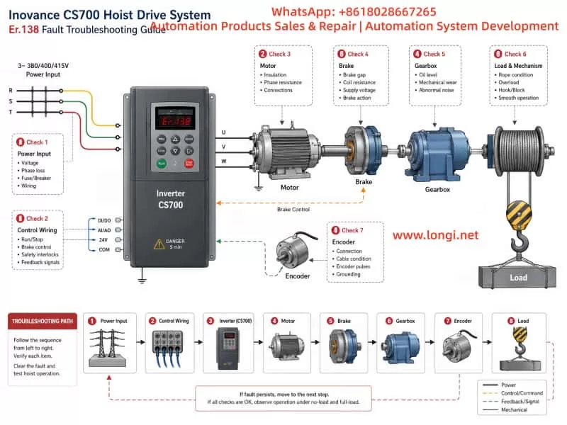
11. Recommended Field Troubleshooting Procedure
The following workflow can be used when a CS700 crane inverter displays Er.138.
Step 1: Confirm the Display Carefully
Verify that the display is truly Er.138 and not a similar-looking code caused by LED digit interpretation.
Take a clear photo and record:
- Fault code
- Load condition
- Operating direction
- Running speed
- Whether the brake was open
- Whether the fault occurred during start, run, stop, or reverse
Step 2: Record the Fault Condition
Document:
- Lifting or lowering direction
- No-load, light-load, or full-load condition
- Cold machine or hot machine condition
- Immediate or delayed trip
- Frequency of occurrence
- Recent maintenance history
- Recent replacement of motor, brake, encoder, gearbox, or inverter
- Whether reset is possible
Step 3: Inspect Main Power and Wiring
After isolating power and waiting for capacitor discharge:
- Check incoming supply voltage.
- Check U/V/W connections.
- Check motor cable condition.
- Check grounding.
- Check motor insulation.
- Check contactors and terminals.
- Check for heat damage or loose connections.
Step 4: Verify Motor Parameters
Compare inverter settings with the motor nameplate. Back up existing inverter parameters before making changes. Enter correct motor data and perform a suitable motor tuning procedure.
Step 5: Inspect Brake Operation
Confirm brake release voltage, brake coil condition, rectifier output, contactor operation, brake gap, brake shoe condition, and actual mechanical opening movement.
Step 6: Inspect Mechanical Components
Check the gearbox, bearings, drum, rope, pulley, coupling, and brake wheel. If necessary, separate the motor from the mechanical load and test the motor alone.
Step 7: Check Encoder Feedback
For closed-loop systems, verify encoder voltage, wiring, shield grounding, signal integrity, coupling, direction, resolution, and PG interface condition.
Step 8: Inspect Braking Components and Motion Parameters
Check braking resistor value, resistor power, braking-unit condition, deceleration time, acceleration time, speed-change logic, and brake timing parameters.
Step 9: Perform Low-Risk Test Runs
After repairs or adjustments, begin with low-speed no-load testing. Increase speed and load gradually. Do not immediately perform full-load lifting before confirming that current, speed, brake action, and mechanical operation are stable.
12. Common Mistakes to Avoid
Mistake 1: Repeatedly Pressing RESET
Resetting only clears the current fault condition. It does not remove the underlying cause.
Mistake 2: Restoring Factory Settings Without Backup
A crane inverter contains critical parameters for motor data, brake timing, speed settings, limit logic, encoder configuration, and control terminals.
Restoring factory settings can create new hazards, including incorrect direction, unsafe brake timing, or loss of operational logic.
Mistake 3: Bypassing the Mechanical Brake
The brake is a safety device. Forcing it open or bypassing it may lead to uncontrolled load movement.
Mistake 4: Replacing the Inverter Without Checking the System
A new inverter may fail again if the true cause is brake drag, encoder failure, low input voltage, damaged motor cable, gearbox resistance, or incorrect motor settings.
Mistake 5: Solving Every Problem by Changing Parameters
Parameter changes should be based on measurements and system verification. Mechanical, electrical, and feedback faults cannot be reliably corrected through parameter adjustment alone.
13. Preventive Maintenance Recommendations
To reduce Er.138-type faults and other crane-drive failures, establish a preventive maintenance plan.
Monthly checks should include:
- Cabinet cleaning
- Cooling fan condition
- Filter condition
- Terminal tightening
- Grounding inspection
- Contactor condition
- Brake movement observation
Quarterly checks should include:
- Brake coil voltage
- Brake rectifier condition
- Brake shoe wear
- Brake gap setting
- Brake wheel condition
- Motor cable inspection
- Encoder connector inspection
Semi-annual checks should include:
- Motor insulation resistance
- Gearbox lubrication
- Bearing condition
- Braking resistor condition
- Braking-unit connections
- Parameter backup
- Fault-history review
Annual checks should include:
- Full inspection of brake timing
- Motor parameter verification
- Encoder feedback verification
- Mechanical load test
- Safety interlock verification
- Wire rope and drum inspection
- Gearbox efficiency evaluation
For high-duty crane systems, special attention should be given to brake wear, contactor life, braking resistor heat aging, fan life, encoder cable integrity, motor bearings, and gearbox lubrication.
14. Conclusion
When an Inovance CS700 crane inverter displays Er.138, it should not be treated as a simple “fault 138.” It should first be interpreted as a Level-1 drive fault, requiring careful evaluation of the entire hoisting system.
The investigation should include:
- Input power quality
- Output wiring
- Motor condition
- Motor parameters
- Brake release and brake timing
- Mechanical resistance
- Encoder feedback
- Braking resistor and braking unit
- Acceleration and deceleration settings
- Load condition and operating sequence
The objective is not merely to reset the inverter and resume operation. The real goal is to identify why the protection was triggered and verify that the lifting system can return to service safely.
For crane equipment, safe recovery is always more important than rapid recovery.