
During industrial maintenance, second-hand drive inspection, PLC communication debugging, HMI integration, and remote technical support, engineers often need to verify whether the embedded fieldbus interface of an ABB ACS580 drive is functioning correctly. The ACS580 includes an internal EFB (Embedded Fieldbus) interface that can operate as a Modbus RTU slave. With a USB-to-RS485 converter, a computer, and a serial communication tool, it is possible to perform complete communication testing, including register reading, control word writing, frequency reference adjustment, remote start/stop control, and fault reset.
This method is extremely practical because it does not require a PLC, HMI, or ABB commissioning software. As long as the RS485 physical layer and the drive parameters are configured correctly, engineers can directly determine whether the communication port, Modbus settings, control logic, and remote control chain are operating properly.
This article explains the complete process of ACS580 Modbus RTU communication testing using a USB-RS485 converter and a serial assistant tool. It covers wiring, parameter configuration, serial software settings, Modbus frames, control word logic, startup and stop procedures, common faults such as 6681 EFB communication loss and AFE1/off2 emergency stop, as well as communication instability caused by electromagnetic interference during drive operation.
1. ACS580 EFB Interface and RS485 Wiring
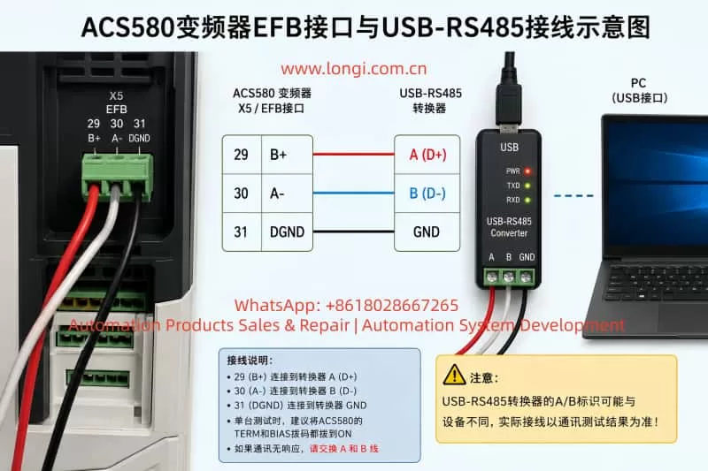
The ACS580 control board includes a three-pin EFB terminal used for embedded fieldbus communication. This interface can be used directly for Modbus RTU testing.
Typical terminal definitions are:
| ACS580 Terminal | Function |
|---|---|
| 29 | B+ |
| 30 | A- |
| 31 | DGND |
The wiring between the ACS580 and the USB-RS485 converter is typically:
| ACS580 X5/EFB | USB-RS485 Converter |
|---|---|
| 29 B+ | RS485 A/B |
| 30 A- | RS485 opposite line |
| 31 DGND | GND |
One important point is that many USB-RS485 converters use inconsistent A/B or D+/D- labeling. Cheap converters especially may reverse the line naming compared to the drive definition. Therefore, if the parameters and serial settings appear correct but no communication occurs, the first troubleshooting step should be swapping the A and B communication wires.
For single-drive bench testing, it is recommended to enable both TERM and BIAS on the ACS580 communication interface. This improves communication stability in short-distance point-to-point testing.
For long-term industrial use, twisted-pair shielded cable should be used for the A/B communication pair. The shield should typically be grounded at one end only to avoid ground loop current.
2. ACS580 Parameters Required for Modbus RTU Communication
To allow Modbus RTU control, the embedded fieldbus interface must first be enabled and configured correctly.
Recommended communication parameters:
| Parameter | Recommended Value | Description |
|---|---|---|
| 58.01 Protocol Enable | Modbus RTU | Enable embedded fieldbus |
| 58.03 Node Address | 1 | Modbus slave address |
| 58.04 Baud Rate | 9.6 kbps | Matches serial tool setting |
| 58.05 Parity | 8 Even 1 | Matches serial tool |
| 58.06 Communication Control | Refresh Settings | Apply communication changes |
| 58.25 Control Profile | ABB Drive | Enables ABB control word format |
After modifying the 58-group parameters, 58.06 “Refresh Settings” must be executed, or the drive must be power-cycled. Many communication failures occur simply because the communication settings were not refreshed.
The command source and frequency reference source must also be assigned to EFB:
| Parameter | Recommended Value | Description |
|---|---|---|
| 19.11 EXT1/EXT2 Selection | EXT1 | Use external control set 1 |
| 20.01 EXT1 Commands | Embedded Fieldbus / EFB | Start/stop via Modbus |
| 28.11 EXT1 Frequency Reference 1 | EFB Reference 1 | Frequency reference from Modbus |
| 19.01 Operating Mode | Scalar Hz / Speed Mode | Common for testing |
If 20.01 is not assigned to EFB, the drive may acknowledge Modbus commands without actually starting. If 28.11 is not assigned to EFB Reference 1, writing frequency values may not affect the drive output.
During testing, it is also recommended to temporarily disable communication-loss trips:
| Parameter | Recommended Temporary Value |
|---|---|
| 58.14 Communication Loss Action | No Action |
| 58.15 Communication Loss Mode | Any Message |
| 58.16 Communication Loss Time | 30 seconds or longer |
This prevents fault 6681 from occurring while manually testing communication using a serial tool.
3. Serial Assistant Software Configuration
The USB-RS485 converter driver must first be installed so that Windows recognizes the device as a COM port.
Typical serial settings:
| Setting | Value |
|---|---|
| COM Port | COM3 / COM4 / etc. |
| Baud Rate | 9600 |
| Data Bits | 8 |
| Parity | Even |
| Stop Bits | 1 |
| Flow Control | None |
| Send Format | HEX |
| Receive Format | HEX |
If ACS580 parameter 58.05 is set to “8 Even 1,” the serial assistant must also use Even parity. A parity mismatch will prevent proper communication.
Another critical point involves CRC handling. Some serial tools automatically append Modbus CRC bytes. If CRC auto-generation is enabled, the user should only enter the Modbus frame without CRC. If the complete frame including CRC is entered manually while auto-CRC is still enabled, the resulting frame becomes invalid.
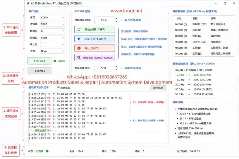
Example read command:
01 03 00 00 00 06 C5 C8
If CRC auto-generation is disabled, the complete frame above should be transmitted exactly as shown.
4. Read Registers Before Attempting Startup
The first communication test should always be a register read operation rather than an immediate start command.
Command for reading registers 400001–400006:
01 03 00 00 00 06 C5 C8
Frame meaning:
| Bytes | Description |
|---|---|
| 01 | Slave address |
| 03 | Read holding registers |
| 00 00 | Starting register |
| 00 06 | Read 6 registers |
| C5 C8 | CRC |
A typical response:
01 03 0C 00 00 00 00 00 00 00 00 11 33 00 00 95 E4
If the drive responds, the physical layer, slave address, baud rate, parity, and CRC are likely correct.
ACS580 communication diagnostics can also be monitored:
| Parameter | Description |
|---|---|
| 58.08 Received Packets | Valid incoming frames |
| 58.09 Sent Packets | Valid outgoing frames |
| 58.11 UART Errors | Serial framing/parity errors |
| 58.12 CRC Errors | Invalid CRC or communication noise |
5. Writing Frequency References
Under the ABB Drive profile, the frequency scaling is typically:
50Hz = 20000
Frequency calculation:
Reference Value = Target Frequency / 50 × 20000
Example for 10Hz:
10 / 50 × 20000 = 4000
4000 decimal equals 0FA0 hexadecimal.
Command to write 10Hz into register 400002:
01 06 00 01 0F A0 DD 82
The drive should echo the same frame back if the command is accepted.
Common frequency conversions:
| Frequency | Decimal | HEX |
|---|---|---|
| 5Hz | 2000 | 07D0 |
| 10Hz | 4000 | 0FA0 |
| 20Hz | 8000 | 1F40 |
| 30Hz | 12000 | 2EE0 |
| 50Hz | 20000 | 4E20 |
6. Control Word Logic: Reset, Run, and Stop
The ACS580 control word is the key element for remote control via Modbus.
Common control words:
| Control Word | Function |
|---|---|
| 04F7 | Fault Reset |
| 047F | Run |
| 047E | Stop |
Fault reset command:
01 06 00 00 04 F7 CA 8C
Run command:
01 06 00 00 04 7F CA EA
Stop command:
01 06 00 00 04 7E 0B 2A
For stable operation, it is better to periodically write both control word and frequency reference together using Modbus function code 10.
10Hz run command:
01 10 00 00 00 02 04 04 7F 0F A0 C6 CF
Stop and zero-frequency command:
01 10 00 00 00 02 04 04 7E 00 00 92 87
In practical testing, a periodic transmission interval of 200–500ms proved much more stable than one-shot commands. With a 1-second interval, the panel sometimes displayed the frequency reference without actual output. At 500ms intervals, the drive produced stable output frequency and cooling fan operation.
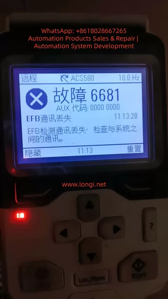
7. Understanding Fault 6681: EFB Communication Loss
Fault 6681 indicates that the drive detected a communication loss on the embedded fieldbus.
Typical causes:
- The drive command source is assigned to EFB, but the PC is not continuously transmitting Modbus frames.
- Communication-loss action remains enabled during manual testing.
- Parameters were copied from another drive, but no real-time control word is being transmitted after power-up.
During manual testing, it is recommended to disable communication-loss trips temporarily. However, in actual industrial applications, communication supervision should remain active and PLCs should continuously refresh control words and references.
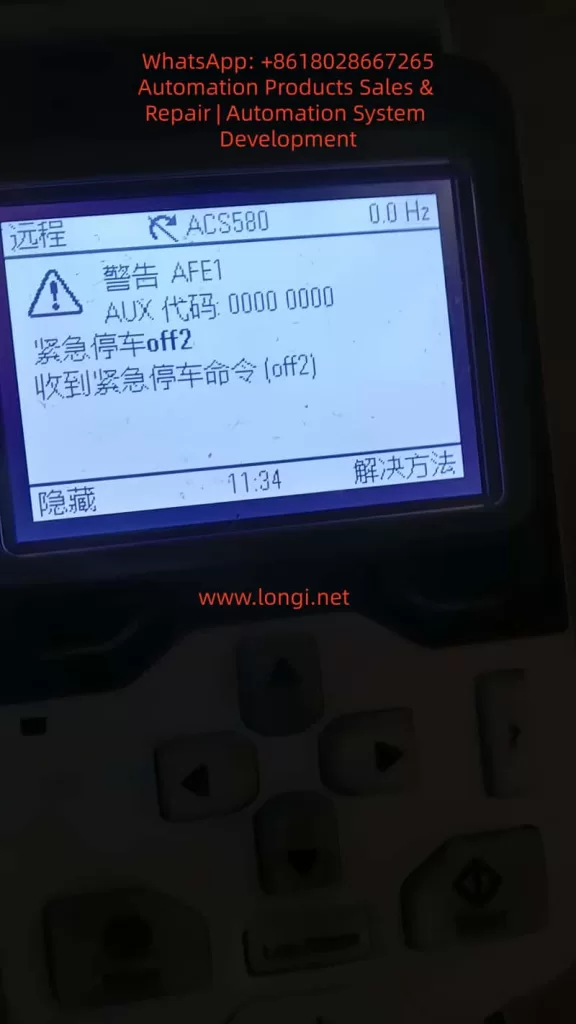
8. Understanding AFE1 / OFF2 Emergency Stop
Another common issue is the AFE1 warning showing “Emergency Stop OFF2.”
This is not always caused by hardware emergency stop wiring. It can also occur when the fieldbus control word is incomplete or invalid.
Example:
06.01 = 408 hex
In this state, Off1/Off2/Off3 bits may not be properly enabled.
Under ABB Drive control word logic:
- OFF2 bit = 1 → OFF2 inactive, operation allowed
- OFF2 bit = 0 → Emergency stop active
Therefore, after power-up or communication interruption, the drive may interpret the control word as an OFF2 command.
The practical solution is:
- Send fault reset 04F7
- Begin periodic transmission of 047F + frequency reference
Once the control word stabilizes at 047F, the OFF2 warning disappears.
9. Local Mode vs Remote Mode
For Modbus control, the drive must operate in Remote mode.
In Local mode, panel commands have priority, and Modbus commands may appear to work without actually controlling the drive.
Therefore:
| Mode | Description |
|---|---|
| Local | Panel control priority |
| Remote | External control active |
| Remote + EFB | Modbus control active |
A successful Modbus test must ultimately operate in Remote mode.
10. Parameter Copying Between Drives
Copying parameters from one ACS580 to another does not copy the current control word state.
The copied drive still requires:
- Power cycle
- Fault reset
- Continuous control-word transmission
Copied parameters include communication settings and command-source assignments, but not the live Modbus control state.
11. USB-RS485 Communication Instability During Drive Output
If the COM port disappears from Windows Device Manager while the drive is running, the issue is usually electromagnetic interference rather than software alone.
Variable-frequency drives generate strong PWM-related common-mode noise on motor cables.
Cheap CH340-based USB-RS485 adapters are especially vulnerable.
Recommended solutions:
- Use isolated industrial USB-RS485 converters.
- Keep USB and RS485 cables away from motor output cables.
- Use twisted-pair shielded communication cable.
- Install ferrite cores on USB cables.
- Use rear motherboard USB ports instead of front-panel ports.
- Enable TERM and BIAS for single-drive testing.
12. Recommended Complete Testing Procedure
Step 1: Configure Drive Parameters
Set all required EFB and Modbus parameters.
Step 2: Read Registers
Send:
01 03 00 00 00 06 C5 C8
Step 3: Reset Faults
Send:
01 06 00 00 04 F7 CA 8C
Step 4: Start Drive at 10Hz
Transmit periodically:
01 10 00 00 00 02 04 04 7F 0F A0 C6 CF
Step 5: Stop Drive
Send:
01 10 00 00 00 02 04 04 7E 00 00 92 87
13. Conclusion
Testing an ACS580 using a USB-RS485 converter and a serial assistant tool is an extremely effective method for verifying embedded Modbus RTU communication without requiring PLCs or engineering software.
A successful communication test requires more than simply receiving Modbus responses. Proper EFB command assignment, valid ABB control words, periodic transmission timing, remote mode selection, and stable hardware wiring are all critical.
The most common troubleshooting issues include reversed A/B wiring, missing communication refresh, incorrect parity, duplicated CRC generation, communication-loss supervision, OFF2 emergency stop logic, and electromagnetic interference affecting USB-RS485 adapters.
Once the Modbus control sequence is understood, ACS580 communication testing becomes a reliable and repeatable process for maintenance, refurbishment, commissioning, and customer technical support.