In-depth Analysis of Rhymebus RM6 Series Inverters: From Principles to Troubleshooting — Using SC Fuse Open Protection as an Example
Introduction
In the field of modern industrial automation and energy saving, the AC Variable Frequency Drive (VFD) has become the core equipment for motor speed control. By changing the power frequency and voltage, it achieves precise control of three-phase asynchronous motors, significantly improving system efficiency, reducing energy consumption, and providing rich protection functions.
Rhymebus Corporation, a professional manufacturer with over 35 years of experience in power electronics, has seen its RM6 series inverters widely applied in textiles, food processing, fluid machinery, HVAC (Heating, Ventilation, and Air Conditioning), and elevators due to their reliable performance, comprehensive protection mechanisms, and flexibility for various applications.
The RM6 series adopts advanced IGBT control technology and digital signal processing, with an output frequency range of 0.1~400Hz. It supports V/F control mode, PID closed-loop regulation, RS-485 Modbus communication, and other functions. The power range covers 0.5HP to several hundred HP, with voltage levels including 200V and 400V series. The overload capacity is divided into heavy-duty (150% for 1 minute) and light-duty (120% for 1 minute), suitable for constant torque and variable torque loads.
This article uses the common user fault code “SC” (Fuse Open Protection) as a starting point to systematically analyze the structure, working principle, installation and debugging, parameter optimization, and fault diagnosis of the RM6 series inverters, providing practical technical guidance to help engineers and maintenance personnel improve equipment reliability and service life.
Structure and Working Principle of the RM6 Series Inverter
The RM6 series inverter adopts the classic three-phase rectifier-inverter topology, with the main components including:
Rectifier Section: Input three-phase AC 380-480V (or 200V series) is rectified by an uncontrolled diode bridge, outputting a DC bus voltage (approximately 540V DC for 380V input).
Filter Section: The DC link capacitor smooths the ripple to provide a stable DC voltage. Some models support external DC reactors (DCL) to suppress harmonics.
Inverter Section: The core uses an IGBT power module to generate three-phase variable frequency/voltage output (U, V, W terminals) through SPWM (Sine Wave Pulse Width Modulation) or SVPWM to drive the motor.
Control Section: Based on DSP or MCU, it integrates analog inputs (0-10V/4-20mA), multi-function digital terminals, PID controller, and RS-485 interface.
Protection Circuit: Includes hardware/software protection such as Overcurrent (OC), Overvoltage (OE), Undervoltage (LE1), Overheat (OH), Ground Fault (GF), and Fuse Open (SC).
Working Principle and Control Logic The working principle is based on Voltage/Frequency (V/F) control: maintaining a constant V/F ratio to ensure stable motor magnetic flux, avoiding field weakening or saturation. The RM6 supports multiple V/F curves (linear, energy-saving, square law, etc.) and integrates the following key functions:
Slip Compensation (Parameter F_050)
AVR (Automatic Voltage Regulation, F_093)
Stall Prevention (F_070~F_074) to prevent overcurrent or stalling during acceleration, constant speed, or deceleration.
Energy-Saving Application Features The RM6 is particularly prominent in energy-saving applications:
For square torque loads such as fans and water pumps, it reduces output voltage during light loads to reduce copper and iron losses, achieving 30%-60% energy savings.
The built-in PID function (F_153~F_195) supports constant pressure/current/temperature/flow control, suitable for air conditioning cooling towers and constant pressure water supply systems.
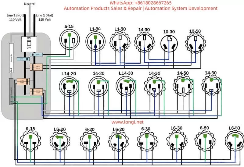
(The image above is a typical three-phase VFD wiring schematic, showing the connection of input R/S/T, output U/V/W, and ground PE. The actual RM6 series is similar.)
Installation and Wiring Specifications for the RM6 Series
Correct installation and wiring are the first steps to avoiding faults (such as SC). According to the RM6 manual:
Environmental and Heat Dissipation Requirements
Environment: Install on a metal fireproof surface. Ambient temperature <50°C (inside the control panel), humidity <90%RH, and no corrosive gases. IP20 protection rating; avoid direct contact with live parts.
Heat Dissipation: For forced air-cooled models, ensure the air duct is unobstructed; fans require regular maintenance.
Power and Wiring Specifications
Circuit Breaker: Configure MCCB or NFB at the input (rated current 1.5~2 times the inverter’s rated current).
Reactor: Connect an external ACL (AC Reactor) when the power supply capacity is >10 times the inverter’s rated capacity or >500kVA to suppress harmonics.
Grounding: The PE terminal must be reliably grounded. Connect the motor housing to the inverter PE using 75°C copper wire; the cross-sectional area depends on the model (e.g., at least 2.5mm² for a 400V 17A model).
Output Side: U/V/W connect directly to the motor.
If cable length >30m, it is recommended to add an output ACL to suppress dV/dt.
Prohibited: Do not install contactors or capacitors on the output side.
Control Wires: Use shielded twisted pairs separated from the main circuit wiring; length <20m (for UP/DOWN control).
Pre-energization Check Wiring errors (such as output short circuits or poor grounding) are the main causes of SC faults. The post-installation process:
Check DC bus voltage with no load.
Wait for the CHARGE light to turn off (5~20 minutes) and ensure the voltage between P/+ and N/- is <25V before operating.
Then connect the motor for testing.
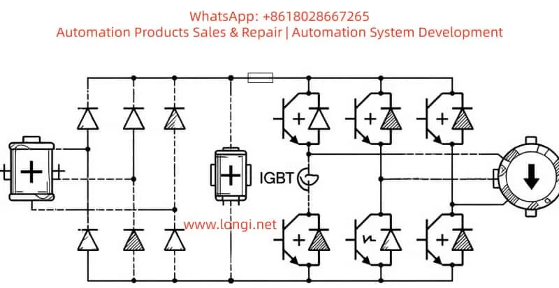
(PWM VFD working principle diagram, showing the SPWM generation process; RM6 uses similar technology.)
Parameter Settings and Optimization Strategies
The RM6 series has rich parameters (F_000~F_220+), with factory defaults suitable for heavy-duty mode.
Fans/Pumps: Enable energy-saving mode (F_102=1) and reduce stall prevention level to 80%.
Heavy Machinery (e.g., extruders): Extend acceleration time to avoid OC/SC triggering.
Anti-misoperation: Lock parameters (F_092) to prevent accidental changes.
SC Fault Code Details: Fuse Open Protection
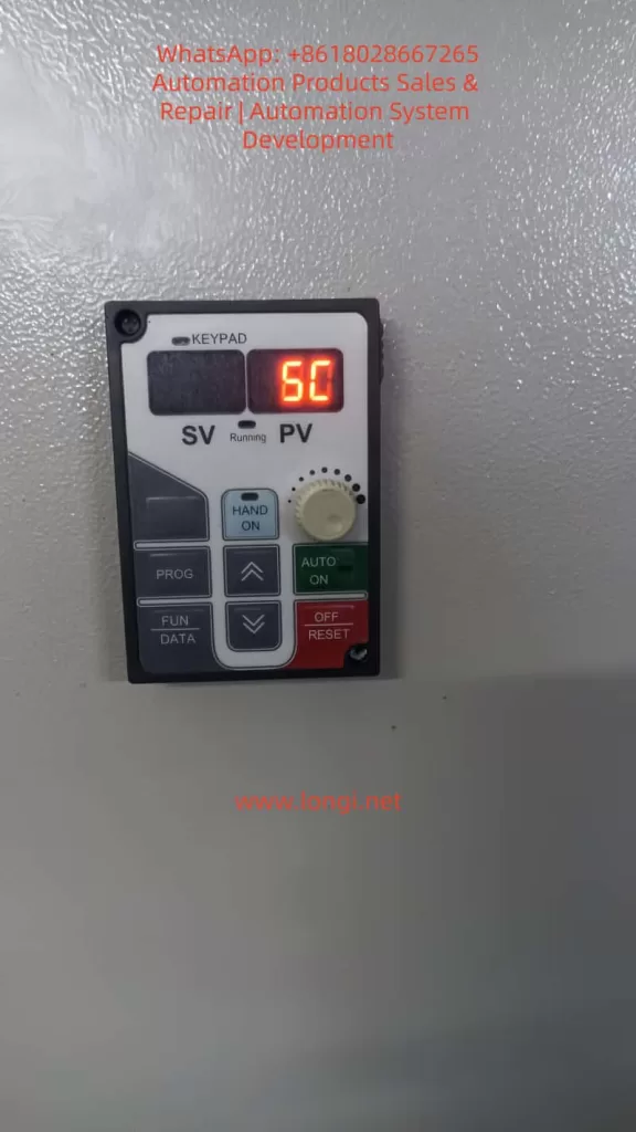
The RM6 series fault display uses the KEYPAD panel. The SC code corresponds to “Fuse Open Protection” (保險絲開路保護).
Fault Meaning The internal fuse has blown or the IGBT module has failed, causing the main circuit to be interrupted. The manual specifies that causes include an internal fuse open circuit or damage to the IGBT power module.
Common Trigger Causes
Output Short Circuit: Short circuit between U-V, V-W, W-U, or any phase to ground (cable damage, motor winding failure, wiring error).
Ground Leakage: Insulation resistance <100MΩ (tested with a 500V megger), causing high current.
IGBT Breakdown: Overvoltage spikes, overheating, aging, or manufacturing defects cause IGBT short circuits, instantly blowing the fuse with high current.
External Overload/Impact: Load jamming during startup, motor stall, or frequent starts/stops.
Improper Wiring: Mixing up input/output or lack of grounding.
Diagnosis and Troubleshooting Steps (High voltage operation requires professionals)
Power Off and Discharge: Turn off power, wait for the CHARGE light to go out (5~20 minutes), and measure voltage between P/+ and N/- to ensure it is <25V.
External Inspection:
Remove U/V/W cables.
Use a multimeter to measure resistance between the three phases (balanced, low value indicates a short).
Perform insulation test to ground (requirement ≥100MΩ).
Use a megger to test motor windings.
Reset Attempt: Power on again and press the RESET key.
If SC disappears, it may have been a transient disturbance.
If it persists, proceed to hardware fault investigation.
Internal Diagnosis:
Check the internal fuse (if accessible, test continuity with a multimeter).
Energy-Saving Case: In HVAC constant pressure water supply systems, using RM6 PID + multi-pump switching can achieve an energy-saving rate of over 40%.
Conclusion
The RM6 series inverter is a reliable choice for industrial energy saving due to its comprehensive protection, ease of use, and high cost-performance ratio. Although the SC fault is a hardware-level issue, most cases can be avoided or quickly located through standardized installation, careful diagnosis of external short circuits, and timely maintenance.
Understanding its principles and protection mechanisms not only solves immediate problems but also enhances the stability and lifespan of the entire system. It is recommended that users record parameters (Appendix F table) and perform regular data backups.