Posted on

User Guide for Lingshida LSD-A1000 Series Inverter

Table of Contents

  1. Introduction to the Inverter Control Panel
    • 1.1 Control Panel Layout and Button Functions
    • 1.2 How to Restore Factory Default Settings
    • 1.3 How to Set and Remove Passwords
    • 1.4 How to Set Parameter Access Restrictions
  2. Terminal Forward/Reverse Control and External Potentiometer Frequency Adjustment
    • 2.1 Parameter Settings and Wiring for Terminal Forward/Reverse Control
    • 2.2 Parameter Settings and Wiring for External Potentiometer Frequency Adjustment
  3. Inverter Fault Codes and Solutions
    • 3.1 Common Fault Code List
    • 3.2 Fault Cause Analysis and Solutions
  4. Summary and Precautions

 Lingshida LSD-A1000 Series Inverter

1. Introduction to the Inverter Control Panel

1.1 Control Panel Layout and Button Functions

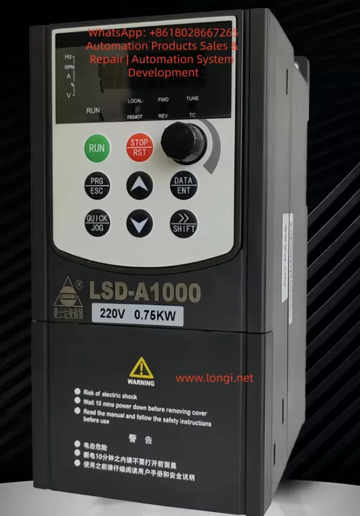
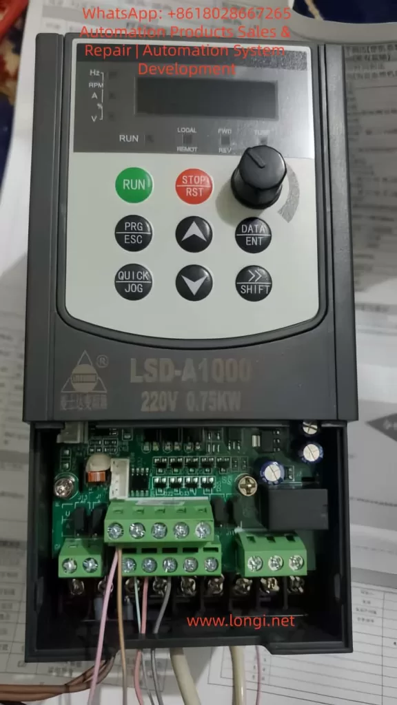
The Lingshida LSD-A1000 series inverter control panel integrates a display screen and multiple functional buttons, facilitating parameter settings, status monitoring, and fault troubleshooting. The panel layout is as follows:

Button/IndicatorFunction Description
RUN (Run)Starts the inverter operation
STOP/RST (Stop/Reset)Stops operation or resets faults
PRG/ESC (Program/Exit)Enters or exits parameter setting mode
DATA/ENT (Data/Enter)Confirms parameter settings or enters the next menu level
△ (Increase)Increases parameter values or selects the previous item
▽ (Decrease)Decreases parameter values or selects the next item
→/SHIFT (Shift)Switches display parameters or selects the modification position
QUICK/JOG (Quick/Jog)Quick function switching or jog operation
Potentiometer KnobAdjusts output frequency or other analog parameters
LED IndicatorsDisplays operating status, fault status, frequency, current, voltage, etc.

LED Indicator Descriptions:

  • RUN (Red): Inverter is running.
  • FWD/REV (Red): Motor is in forward/reverse operation.
  • LOCAL/REMOT (Red): Local/remote control mode.
  • TC (Red): Torque control mode or fault status (flashing indicates a fault).

1.2 How to Restore Factory Default Settings

The Lingshida LSD-A1000 series inverter supports restoring all parameters to factory default values. Follow these steps:

  1. Enter Parameter Setting Mode:
    • Press the PRG/ESC key to enter the function code editing state.
    • Use the △/▽ keys to select FA-11 (Product Number) or FA-12 (Software Version Number) to confirm the current version.
  2. Restore Factory Settings:
    • In the stopped state, press and hold the PRG/ESC key for more than 5 seconds until the display shows the “rES” prompt.
    • Press the DATA/ENT key to confirm the restoration of factory settings.
    • The inverter will restart, and all parameters will be reset to default values.

Note:

  • Restoring factory settings will clear all user-defined parameters, including passwords and PID parameters.
  • After restoration, you need to reconfigure motor parameters (such as rated current and rated frequency).

1.3 How to Set and Remove Passwords

To prevent unauthorized parameter modifications, the Lingshida LSD-A1000 supports password protection.

Setting a Password:

  1. Enter FA-00 (User Password Setting):
    • Press PRG/ESC → Select the FA group → Select FA-00.
    • Enter a 5-digit password (default is 00000).
    • Press DATA/ENT to confirm.
  2. Enable Password Protection:
    • Enter FA-01 (Password Protection Enable):
      • 0: Disable password protection.
      • 1: Enable password protection.

Removing a Password:

  1. Enter the Correct Password:
    • When entering parameter settings, the system prompts for a password.
    • Enter the correct password and press DATA/ENT to confirm.
  2. Reset Password if Forgotten:
    • Press and hold the PRG/ESC key for 5 seconds to restore factory settings (password resets to 00000).

Note:

  • After setting a password, modifying critical parameters (such as F3 group motor parameters) requires entering the password.
  • The manufacturer’s password (for advanced parameters) cannot be cleared by restoring factory settings; contact the manufacturer.

1.4 How to Set Parameter Access Restrictions

To prevent accidental modifications, you can restrict access to certain parameters:

  1. Set Parameter Modification Permissions:
    • The “Change” column in the function code table indicates modification permissions:
      • ★: Can be modified during both operation and stop.
      • ☆: Can only be modified when stopped.
      • ●: Read-only, cannot be modified (such as fault records).
  2. Lock Critical Parameters:
    • After setting a password in FA-00 (User Password), parameters in F3 group (Motor Parameters) and FC group (PID Parameters) cannot be modified without the password.
  3. Lock Buttons:
    • Set via FA-00 (QUICK/JOG Key Function):
      • 0: QUICK/JOG key is disabled.
      • 1: Switch between local and remote control.
      • 2-4: Jog function (to prevent accidental operation).

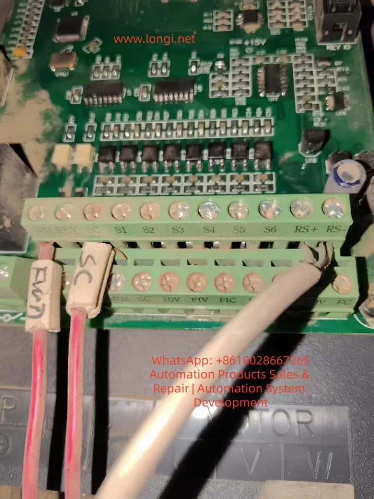
 Lingshida LSD-A1000 Series Inverter is used

2. Terminal Forward/Reverse Control and External Potentiometer Frequency Adjustment

2.1 Parameter Settings and Wiring for Terminal Forward/Reverse Control

The Lingshida LSD-A1000 supports forward/reverse control through DI (Digital Input) terminals.

Parameter Settings:

Function CodeSetting ValueDescription
F6-00 (DI1 Function Selection)1 (Forward Run)DI1 connected for forward operation
F6-01 (DI2 Function Selection)2 (Reverse Run)DI2 connected for reverse operation
F6-11 (Terminal Command Mode)0 (Two-Wire Mode 1)DI1/DI2 control forward/reverse separately

Wiring Steps:

  1. Connect DI1 (Forward) and DI2 (Reverse):
    • Connect DI1 to the forward button or PLC output.
    • Connect DI2 to the reverse button or PLC output.
    • Connect COM to 24V- (common ground).
  2. Set Command Source:
    • F0-21 (Command Source Selection) = 1 (Terminal Command Channel).
  3. Start Testing:
    • Connect DI1, and the motor runs forward.
    • Connect DI2, and the motor runs in reverse.

Note:

  • Ensure F1-06 (Stop Mode) = 0 (Deceleration Stop) to avoid sudden stops.
  • For three-wire control (forward/reverse/stop), set F6-11 = 2 (Three-Wire Mode 1).

2.2 Parameter Settings and Wiring for External Potentiometer Frequency Adjustment

Frequency adjustment can be achieved through AI1 (Analog Input) using an external potentiometer.

Parameter Settings:

Function CodeSetting ValueDescription
F0-02 (Main Frequency Source Selection)2 (AI1)Frequency given by AI1
F6-13 (AI Curve Minimum Input)0.00VPotentiometer minimum voltage corresponds to 0Hz
F6-16 (AI Curve Maximum Input)10.00VPotentiometer maximum voltage corresponds to 50Hz
J13 (AI1 Input Mode)1-2 (0-10V)Voltage input mode

Wiring Steps:

  1. Connect the Potentiometer:
    • Connect the middle pin of the potentiometer to AI1.
    • Connect one end of the potentiometer to +10V (provided by the inverter).
    • Connect the other end of the potentiometer to COM.
  2. Set Frequency Range:
    • F0-09 (Maximum Frequency) = 50.00Hz.
    • F0-12 (Minimum Frequency) = 0.00Hz.
  3. Start Testing:
    • Rotate the potentiometer, and the output frequency changes with the voltage.

Note:

  • The potentiometer resistance is recommended to be 5K-10KΩ.
  • For current input (4-20mA), short J13 to 2-3.

3. Inverter Fault Codes and Solutions

3.1 Common Fault Code List

Fault CodeFault DescriptionPossible Causes
E01Wave-by-Wave Current Limiting FaultHigh starting current, heavy load
E02Acceleration OvercurrentShort acceleration time, motor locked
E03Deceleration OvercurrentShort deceleration time, braking resistor failure
E04Constant Speed OvercurrentSudden load change, motor overload
E05Acceleration OvervoltageHigh input voltage, braking unit failure
E06Deceleration OvervoltageShort deceleration time, braking resistor damage
E11Motor OverloadMotor overheating, poor cooling
E12Input Phase LossLoose power line, blown fuse
E13Output Phase LossMotor line break, contactor failure
E15External FaultExternal emergency stop signal triggered
E16Communication FaultMODBUS communication interruption
E23Running Time ReachedTimer setting triggered stop
E24User-Defined Fault 1DI terminal triggered custom fault

3.2 Fault Cause Analysis and Solutions

E02 (Acceleration Overcurrent)

  • Cause: Acceleration time is too short, or the load inertia is too large.
  • Solution:
    • Increase F0-13 (Acceleration Time 1).
    • Check if the motor is locked.

E05 (Acceleration Overvoltage)

  • Cause: Input voltage is too high, or the braking unit is not enabled.
  • Solution:
    • Check if the input voltage is within 380V±10%.
    • Enable F1-14 (Energy Consumption Braking Point) and connect a braking resistor.

E11 (Motor Overload)

  • Cause: Motor overheating, cooling fan failure.
  • Solution:
    • Check if the motor cooling is normal.
    • Adjust F8-01 (Motor Overload Protection Gain).

E12 (Input Phase Loss)

  • Cause: Loose power line, blown fuse.
  • Solution:
    • Check if the R/S/T terminals are properly connected.
    • Replace the fuse.

E16 (Communication Fault)

  • Cause: MODBUS line disconnection, address conflict.
  • Solution:
    • Check the RS485 line connection.
    • Ensure P0-01 (Communication Address) is unique.

4. Summary and Precautions

  • Control Panel: Familiarize yourself with button functions and set passwords and parameter restrictions reasonably.
  • Terminal Control: Correctly wire DI/AI terminals to avoid misoperation.
  • Fault Troubleshooting: Check power supply, load, and parameter settings one by one according to fault codes.
  • Safety Precautions:
    • Wait 10 minutes after power-off before maintenance.
    • Avoid using in high-temperature or humid environments.

Conclusion The Lingshida LSD-A1000 series inverter is powerful but requires strict operation according to the manual. This guide helps users quickly master basic operations, parameter settings, and fault troubleshooting methods to ensure stable equipment operation. For complex issues, contact the manufacturer’s technical support.
Posted on

In-depth Analysis of Fault 10.10 in SEW MOVIDRIVE® Generation C Drives and Research on Parameter Matching Issues Triggered by Encoder Replacement

Abstract

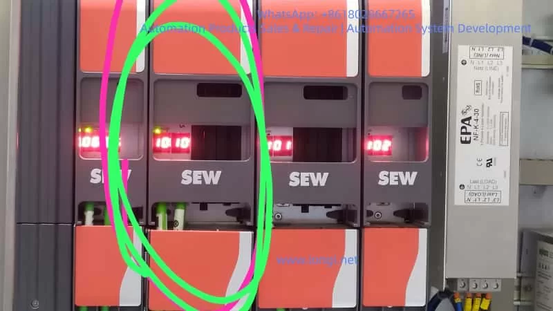
In industrial automation motion control systems, the meanings of servo drive fault codes are diverse. In a recent on-site case, the SEW MOVIDRIVE® Generation C series drive exhibited fault code 10.10 after replacing a SICK encoder. This fault is often misdiagnosed as an encoder not being zero-calibrated, but it is actually an “unsupported setpoint cycle time/data flex layer initialization error,” which falls under the category of parameter-level configuration conflicts. This paper discusses the issue from five dimensions, including drive platform structure and error triggering mechanisms.

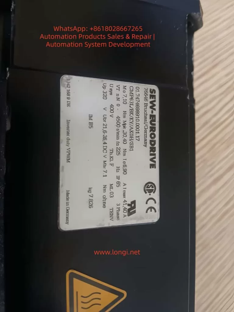
CMP71-0 B637/BK/XAK0.00.17,SEW motor

I. Background Overview: Why Fault 10.10 is Prone to Misdiagnosis

After replacing an encoder in a servo system, it is necessary to re-establish the electrical angle reference, among other things. Most system errors are directly related to encoder hardware, such as 13.xx indicating encoder loss or feedback channel abnormalities. However, in this case, 10.10 (Setpoint Cycle Time unsupported / Data Flex Layer Init Error) is an alarm related to control cycle synchronization mechanism abnormalities. Due to the fact that encoder replacement is often accompanied by parameter reloading and drive initialization, on-site engineers tend to establish a connection between the encoder and the error, leading to misdiagnosis.

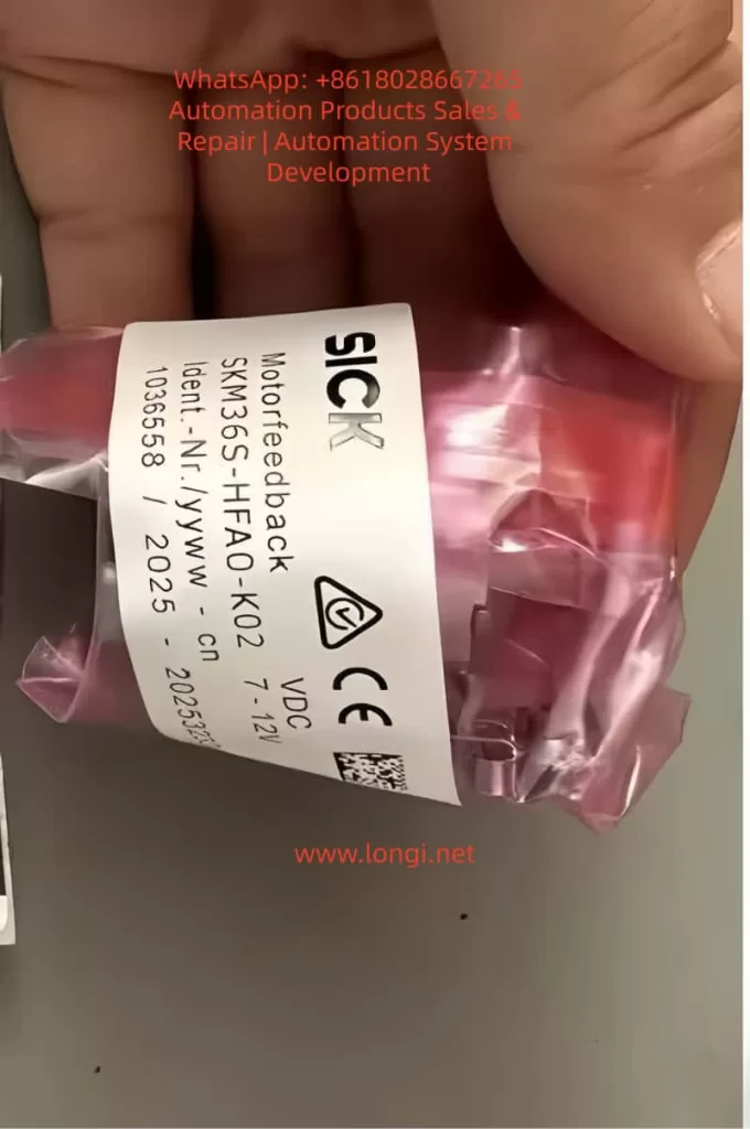
SKM36S-HFA0-K02

II. SEW MOVIDRIVE® Generation C System Architecture and DFL Explanation

The SEW MOVIDRIVE® adopts a multi-layer data processing system, where motion control and other parameters are distributed and synchronized through the DFL (Data Flex Layer). The DFL is responsible for managing the loading and switching of drive parameter sets, interfacing with bus cycles, validating motion setpoint cycles, and synchronizing feedback data with control loops. When the motion setpoint cycle exceeds limits or does not match the hardware, the drive will prohibit output and trigger Error 10.10 to protect the drive.

fault 10.10 ,sew servo

III. Why Encoder Replacement Can Indirectly Trigger 10.10

Although encoder replacement is not the direct cause of the 10.10 alarm, it can affect variables such as electrical angle, resolution, protocol, parameter rewriting, and cycle synchronization after engineering reset. This leads the drive to detect that the old operating cycle scheme cannot be adapted to the current hardware configuration, necessitating the resynchronization of system parameters and cycle settings, thereby triggering 10.10.

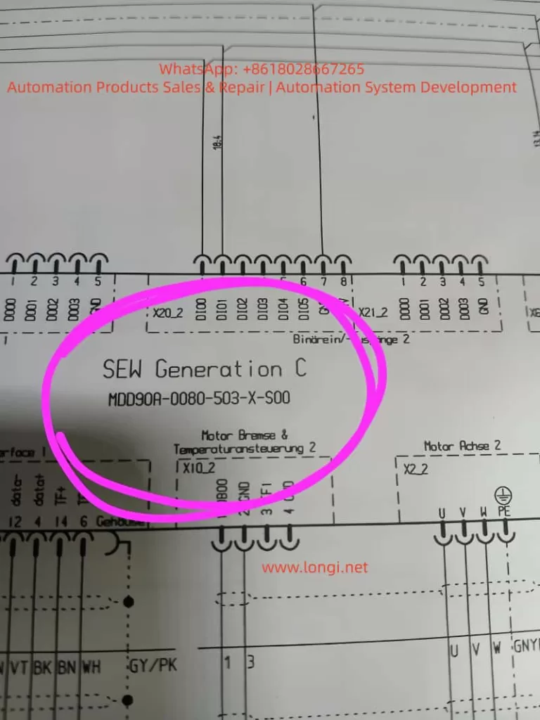
MDD90A-0080-503-X-S00

IV. Technical Troubleshooting Process

Step 1: Confirm Communication Cycle and Drive Support Range
Access the controller/software and check the Communication → Setpoint Cycle Time settings to ensure they are within the recommended range, such as 250us – 2ms for EtherCAT mode. If they exceed the limits, restore them to the supported range.

Step 2: Reinitialize the DFL and Refresh Configuration
Execute Parameter → Data Flex Layer → ReInit, then Save → Reboot Drive.

Step 3: Perform Motor and Feedback Re-matching
Conduct Motor Commission → Encoder Calibration and Rotor Alignment / Commutation Identification.

Step 4: Check for Contradictions in Key Control Parameters
Verify parameters such as Encoder Type, Feedback Resolution, Motor Pole Pairs, and Control Mode to ensure they match. After resetting parameters, execute Save + Reboot.

Step 5: Synchronize Cycles if Involving an Upper-level PLC
Especially in cases of EtherCAT/Profinet/Master Clock, ensure that PLC → Sync Cycle = Inverter Cycle and Clock Drift < 5%.

V. Quick-judgment Experience Rules for Fault 10.10

PhenomenonQuick Conclusion
Error reported immediately after encoder replacement → but encoder is readableHigh probability of cycle/parameter storage not being rebuilt
Brief operation after reset, then error recurs after a few secondsTypical manifestation of setpoint cycle mismatch
Returns to normal when original encoder is reinstatedParameter adaptation issue, not a hardware abnormality
Accompanied by output prohibitionOutput Stage Inhibit has been triggered
10.10 does not indicate a faulty encoder; it means the drive believes it cannot operate safely with the current cycle.

VI. Final Conclusions

The occurrence of 10.10 in SEW Generation C MOVIDRIVE drives is not due to encoder hardware failure but rather due to system setpoint cycle or DFL initialization failure.
Encoder replacement is one of the诱因 (contributing factors); the essence lies in parameter mismatch and sampling/cycle conflicts.
Most on-site cases can be resolved by reconfiguring the cycle → reinitializing the DFL → calibrating the encoder and electrical angle.
Class 10 alarms are of the application stop level, with the output stage locked, and must be addressed before continuing operation.

VII. Engineering Recommendations

  • When replacing an encoder, zero-point/pole-pair calibration must be performed. Do not misclassify 10.10 as an encoder fault.
  • Form a standard inspection unit for system debugging: correct feedback type, matched resolution, control cycle meeting drive hardware requirements, successful DFL initialization, and verification after saving and restarting.
  • For high-speed bus servo projects, it is recommended to lock the cycle within the 250 – 500us range.
  • It is advisable to back up parameters before release to avoid re-encountering issues during secondary maintenance.
Posted on

In-depth Analysis and Practical Guide: Handling the Err.23 Dynamic Ground Short Circuit Fault on KCLY KOC600 Inverters

Introduction: The “Safety Red Line” in Inverter Protection

In modern industrial automation, the inverter is the heart of the motor drive system, and its stability directly impacts production efficiency. The KOC600 Series High-Performance Vector Inverter by Shenzhen Kechuan Liyuan (KCLY) is widely recognized for its precision and robust protection features.

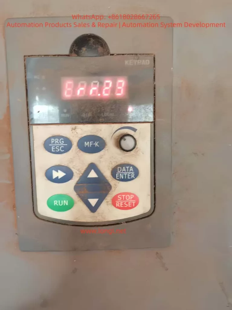
However, maintenance engineers occasionally encounter the Err.23 (Output to Ground Short Circuit) fault. A particularly puzzling scenario is when the inverter starts normally but suddenly trips with Err.23 after running for a period. This “dynamic fault” tests a technician’s diagnostic skills and threatens production continuity. This article provides a deep dive into the mechanisms, diagnostics, and solutions for Err.23 based on the KOC600 logic.


err.23

Chapter 1: Understanding Err.23 – The Technical Logic

1.1 What is an Output to Ground Short Circuit?

According to the KOC600 manual, Err.23 occurs when an unintended current path forms between the inverter’s output terminals (U, V, W) and the Ground (PE).

In a healthy state, the three-phase output currents are balanced; their vector sum should be near zero ($\vec{I_u} + \vec{I_v} + \vec{I_w} \approx 0$). If a phase leaks to the ground, this balance is broken. Internal Hall-effect current sensors detect this residual current. If it exceeds the safety threshold, the drive immediately blocks PWM output and triggers Err.23 to protect the internal IGBT power modules from destruction.


Chapter 2: Why Does it Fail After “Running for a While”?

When a fault occurs after minutes or hours of operation rather than at startup, it suggests a “dynamic” issue rather than a hard short circuit.

2.1 Heat-Induced Insulation Degradation

This is the most common cause. As the motor windings or cables heat up during operation:

  • Mechanism: Micro-cracks in insulation may hold under cold conditions. As temperatures rise, materials expand or moisture evaporates into high-pressure pockets, causing the insulation resistance to drop momentarily and creating a flashover to the ground.
  • Symptoms: The fault occurs once the motor reaches its rated load or thermal equilibrium.

2.2 Cumulative Leakage from Cable Capacitance

  • Mechanism: Inverters output high-frequency PWM waves. Long cables act as capacitors between the conductors and the earth.
  • Formula: $I = C \cdot \frac{dv}{dt}$.As operation continues, if humidity changes or the carrier frequency is set too high, high-frequency leakage current hits the protection circuit. At certain frequency points, resonance may cause the current peak to exceed the Err.23 threshold.

2.3 Environmental Factors: Condensation and Dust

In humid environments, temperature differences can cause condensation inside the motor terminal box. Initially, the system runs fine, but as moisture accumulates or mixes with conductive dust, it eventually creates a path to the chassis.


Chapter 3: The “Five-Step” Field Diagnostic Procedure

Step 1: Check Fault Scene Data (bC Parameter Group)

The KOC600 records vital data at the moment of failure. Before resetting, check the bC Group:

  1. bC-03: Output Frequency at fault.
  2. bC-04: Output Current at fault. Check if an overload accompanied the short.
  3. bC-05: Bus Voltage at fault. Fluctuations here can sometimes cause sensor errors.

Step 2: Decoupling Test (Disconnecting Motor Leads)

  • Action: Remove all wires from the U/V/W terminals of the inverter.
  • Conclusion:
    • Still Err.23: Internal hardware damage (IGBT failure or sensor drift).
    • No Error: The inverter is healthy; the fault lies in the cables or motor.

Step 3: Static Insulation Testing (Megger Test)

  • Action: Use a 500V Megohmmeter to measure motor windings to ground.
  • Standard: For a 380V motor, resistance should be > 5MΩ.
  • Warning: Always disconnect the cables from the inverter before using a Megger, or you will destroy the drive’s power modules.

Step 4: Inspect Terminal Box and Cables

Check the motor terminal box for signs of moisture, carbonization (black marks), or loose screws touching the casing. Inspect the cable run for jacket wear, especially in conduits that may hold water.


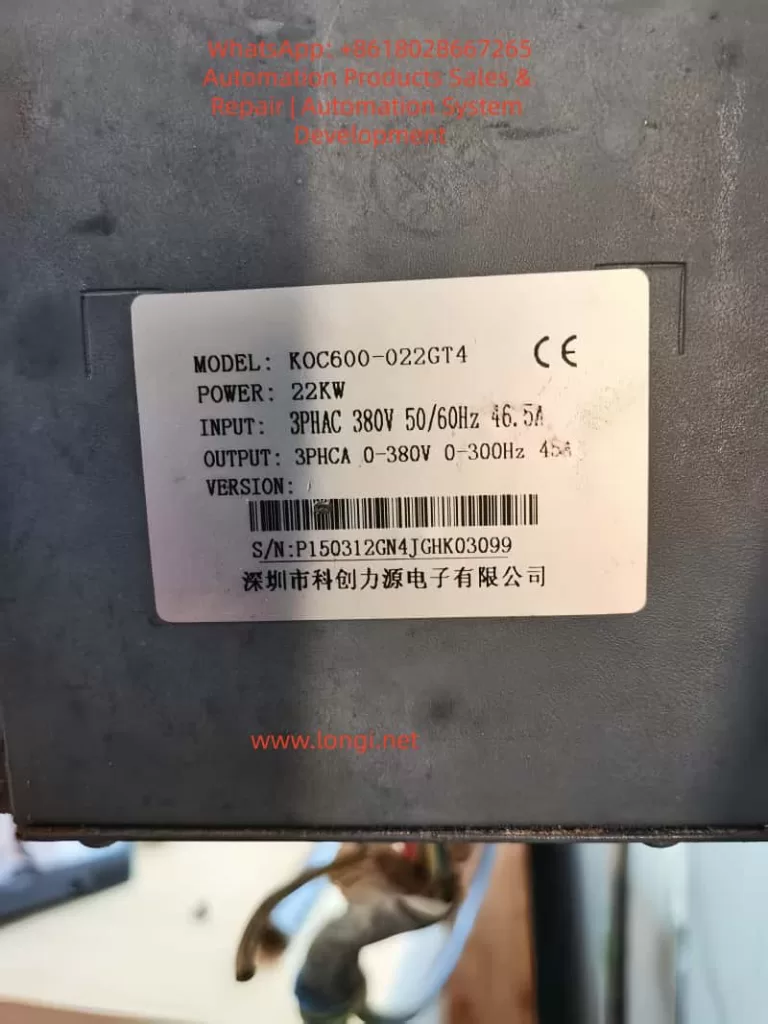
KOX600-022GT4

Chapter 4: Advanced Optimization for KOC600

If no hard short is found, parameter tuning can often resolve nuisance trips caused by leakage or interference.

4.1 Adjust Carrier Frequency (Parameter b0-11)

Higher carrier frequencies increase ground leakage current.

  • Optimization: Decrease the carrier frequency.
  • Effect: This reduces the charging/discharging current of the cable capacitance, often eliminating “ghost” Err.23 reports.

4.2 Installation of Hardware Suppressors

For cable runs exceeding 50 meters:

  1. Output Reactor: Installed between the drive and motor to smooth the $dv/dt$ and suppress leakage.
  2. Zero-sequence Reactor (Ferrite Core): Looping the three output phases through a ferrite core to suppress high-frequency common-mode current.

Conclusion

Err.23 is a vital protective feature of the KOC600. When facing a fault that only appears after running for some time, technicians should apply a logical loop of Data Analysis -> Decoupling -> Insulation Testing -> Parameter Tuning.

Always prioritize safety: ensure the CHARGE lamp is completely off before touching any terminals. Proper maintenance and environmental control are the best defenses against “running-time” faults.

Posted on

In-Depth Analysis and Solution Guide for ERCON Communication Fault in HiMEC HI2xx Series Servo Drives

Introduction

Servo drives, as the core control components of industrial automation equipment, directly determine the operational efficiency and production continuity of devices. The HiMEC HI2xx series servo drives, renowned for their high cost performance and user-friendliness, are widely applied in machine tools, robots, packaging machinery, and other fields. However, in practical use, the ERCON fault (flashing display) caused by communication interruption between the operator (e.g., drive panel) and the main board is one of the most common issues. If unresolved promptly, it can lead to equipment downtime and production stagnation. This article delves into the root causes of the ERCON fault in HI2xx series drives, provides a step-by-step solution guide, and proposes preventive measures to help technicians quickly locate and resolve the problem.

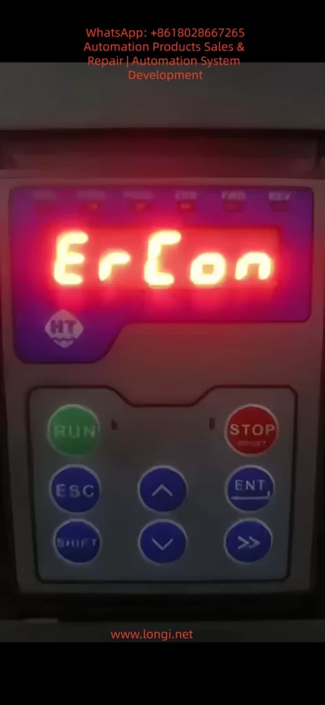
ercon fault

1. Overview of ERCON Fault

1.1 Fault Definition

ERCON (Error Communication) is a communication fault code specific to HiMEC HI2xx series drives, referring to the interruption of the communication link between the operator (e.g., drive panel, handheld programmer) and the main board. When the communication link is abnormal, the operator triggers a communication alarm and displays “ERCON” in a flashing manner, alerting users to check the communication system immediately.

1.2 Fault Impact

  • The operator cannot receive status information from the main board (e.g., motor speed, torque, alarm codes);
  • Control commands (e.g., start, stop, parameter modification) cannot be sent to the main board;
  • The drive enters protection mode, unable to drive the motor normally, and may cause equipment shutdown in severe cases.

2. In-Depth Analysis of Fault Causes

The communication link of HI2xx series drives consists of three parts: operator, communication cable, and main board interface (Figure 1). Any abnormality in these components can trigger the ERCON fault. Below is a detailed breakdown of the causes:

2.1 Communication Cable Fault (Most Common Cause)

The communication cable is the “signal bridge” connecting the operator and the main board, accounting for over 60% of ERCON faults. Specific causes include:

  • Physical damage: Internal conductors break due to long-term vibration or bending (e.g., copper foil fracture in a flat cable);
  • Loose connection: Poor contact between the plug and socket due to vibration or repeated插拔 (e.g., reduced clamping force between a pin header and socket);
  • Electromagnetic interference (EMI): The communication cable is not shielded or laid parallel to power cables (e.g., motor cables), causing EMI to disrupt communication (e.g., RS485 differential signals are submerged by noise);
  • Aging: The insulation layer of the communication cable ages due to high temperature or humidity, leading to short circuits or signal attenuation.

2.2 Interface Fault

The communication interfaces of the operator or main board are “nodes” in the link, accounting for about 30% of faults. Specific causes include:

  • Pin damage: Pins (e.g., pin header, DB9 interface pins) bend or break due to forced插拔 or vibration (e.g., a pin header pin is bent and cannot contact the socket);
  • Oxidation/contamination: Pins oxidize (e.g., copper pins turn black) or the interface is contaminated with dust/oil in humid/dusty environments, increasing contact resistance and blocking signal transmission;
  • Lock failure: The plug lock (e.g., flat cable clip) breaks due to aging, causing the plug to loosen and lose contact.

2.3 Equipment Itself Fault

Faults in the internal communication circuits of the operator or main board account for about 10% of cases. Specific causes include:

  • Operator fault: The operator’s communication chip (e.g., RS485 transceiver) is damaged, unable to send/receive signals;
  • Main board fault: The main board’s communication interface circuit (e.g., UART, RS485 circuit) fails (e.g., capacitor breakdown, resistor burnout), preventing signal processing;
  • Firmware incompatibility: Mismatched firmware versions between the operator and main board (e.g., the operator’s firmware is upgraded but incompatible with the old main board’s communication protocol) disrupt communication.

2.4 Environmental Factors

  • Excessive temperature: The operating environment exceeds the rated range (e.g., HI2xx series operates at 0–45°C), softening the communication cable’s insulation or loosening solder joints on interface pins;
  • High humidity: Ambient humidity exceeds 85%, accelerating pin oxidation or reducing the communication cable’s insulation resistance (e.g., insulation resistance drops from 10MΩ to <1MΩ, causing severe signal attenuation);
  • Vibration: Long-term operation in high-vibration environments (e.g., presses, vibration tables) loosens communication cable plugs or breaks internal conductors.
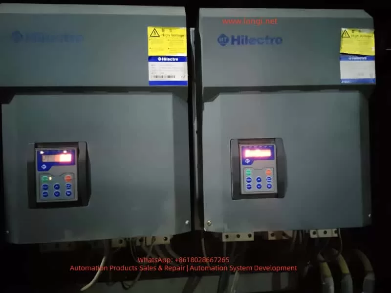
hilectro servo

3. Step-by-Step Solution Guide for ERCON Fault

The following steps follow the principle of “from simple to complex, from external to internal” to help technicians troubleshoot without盲目 disassembling the device.

3.1 Step 1: Power Off and Preliminary Inspection

Purpose: Ensure safety and avoid damaging the device during live operations;初步 locate the fault scope.
Details:

  1. Power off: Turn off the drive’s power switch (e.g., circuit breaker) and unplug the power cord. Wait 5 minutes to discharge the drive’s internal capacitors;
  2. Visual inspection:
    • Check the communication cable for obvious breaks, bends, or insulation damage (e.g., exposed copper foil in a flat cable);
    • Check the connection between the plug and socket for looseness (e.g., the flat cable plug is not fully inserted into the socket);
    • Check the operator and main board interfaces for dust or oil (e.g., black dust in the interface);
  3. Re-plug the communication cable:
    • Release the plug lock (e.g., flat cable clip) and slowly pull out the plug;
    • Check the plug pins for bending or breakage (e.g., a pin header pin is bent);
    • Brush dust from the plug and socket with a brush, then reinsert the plug and ensure the lock is fastened (e.g., the flat cable clip is fully locked).

Notes:

  • Align the pins when plugging/unplugging to avoid bending pins with force;
  • Replace the communication cable if the plug lock fails (avoid using tape, which can cause poor contact).

3.2 Step 2: Continuity Test of Communication Cable

Purpose: Verify if the communication cable has internal breaks and eliminate conductor faults.
Details:

  1. Prepare tools: Multimeter (set to “continuity mode” or “resistance mode”);
  2. Test method:
    • Connect both ends of the communication cable to the operator and main board interfaces (e.g., insert both ends of the flat cable into the operator and main board sockets);
    • Touch the corresponding pins of the communication cable with multimeter probes (e.g., pin 1 to pin 1, pin 2 to pin 2, etc.);
    • If the multimeter shows “continuity” (resistance <1Ω), the conductor is normal; if it shows “open circuit” (infinite resistance), the conductor is broken.

Example:

  • If pin 3 of the communication cable is not continuous to pin 3, the 3rd conductor is broken and the cable needs replacement.

Notes:

  • Ensure both ends of the communication cable are not connected to the operator or main board during testing (to avoid interference from the main board circuit);
  • If the communication cable is a shielded type, test the shield continuity (the shield must be grounded to avoid EMI).

3.3 Step 3: Interface Inspection and Cleaning

Purpose: Eliminate poor contact caused by pin damage, oxidation, or contamination.
Details:

  1. Inspect pins:
    • Use a magnifying glass to check interface pins (e.g., socket pins): look for bending or breakage (e.g., a socket pin is bent);
    • If a pin is bent, slowly adjust it to vertical with tweezers (avoid excessive force to prevent breakage);
    • If a pin is broken, replace the interface (e.g., socket) or main board (if the pin is soldered to the main board).
  2. Clean oxidation and dust:
    • Soak a cotton swab in anhydrous alcohol (≥99% concentration) and wipe the interface pins (e.g., socket pins, plug pins);
    • Brush dust from the interface with a brush;
    • Reinsert the communication cable after the alcohol evaporates.

Notes:

  • Do not grind pins with sandpaper (this damages the pin coating and accelerates oxidation);
  • Use anhydrous alcohol to clean oil stains (avoid corrosive solvents like gasoline or thinner).

3.4 Step 4: Replace the Communication Cable

Purpose: Eliminate faults caused by the communication cable itself (e.g., internal breaks, aging).
Details:

  1. Select the communication cable:
    • Use a HiMEC original communication cable (matching the HI2xx series drive model, e.g., HI2-CABLE-01);
    • If an original cable is unavailable, use a shielded communication cable of the same specification (e.g., RS485 communication cables must be twisted-pair with a shield, and the shield must be grounded).
  2. Replacement method:
    • Disconnect both ends of the old communication cable (operator and main board sides);
    • Insert both ends of the new communication cable into the operator and main board interfaces, ensuring the lock is fastened;
    • Power on the drive: if the ERCON fault disappears, the communication cable fault is resolved.

Notes:

  • Do not use non-original communication cables (incorrect pinout or impedance mismatch may cause communication faults);
  • If the ERCON fault persists after replacing the cable, check the operator and main board interfaces for damage (e.g., bent pins).

3.5 Step 5: Firmware Inspection for Operator and Main Board

Purpose: Eliminate communication faults caused by firmware incompatibility.
Details:

  1. Check firmware versions:
    • View the operator’s firmware version via the menu (e.g., “Parameter Settings” → “Version Information”);
    • View the main board’s firmware version via the drive’s upper computer software (e.g., HiMEC Servo Tool);
  2. Upgrade firmware:
    • If the operator and main board firmware versions are mismatched (e.g., operator firmware V1.2, main board firmware V1.0), upgrade to a compatible version (e.g., both to V1.3);
    • Follow HiMEC’s Firmware Upgrade Guide for firmware upgrades (e.g., via USB or SD card) to avoid device damage.

Notes:

  • Backup parameters before firmware upgrades (to avoid parameter loss after upgrading);
  • Do not upgrade to unvalidated firmware versions (may cause communication protocol incompatibility).

3.6 Step 6: Hardware Inspection of Main Board and Operator

Purpose: Eliminate hardware faults in the operator or main board (e.g., damaged communication circuits).
Details:

  1. Replacement test:
    • If a spare operator is available (e.g., the same model panel), replace the original operator. If the ERCON fault disappears, the original operator is faulty;
    • If a spare main board is available (e.g., the same model main board), replace the original main board. If the ERCON fault disappears, the original main board is faulty.
  2. Circuit testing:
    • Use a multimeter to test the voltage of the main board’s communication interface (e.g., RS485 interface voltage: normally 1–5V between A+ and B-);
    • Use an oscilloscope to test the communication signal (e.g., RS485 differential signal: normally clear waveform without noise);
    • If the voltage or signal is abnormal, repair or replace the main board (e.g., replace the communication circuit chip or resistor).

Notes:

  • Use the same model of device for replacement tests (to avoid compatibility issues);
  • Circuit testing must be performed by a professional technician (to avoid damaging other circuits).

4. Preventive Measures for ERCON Fault

4.1 Regularly Inspect the Communication Link

  • Weekly check: Visually inspect if the communication cable is loosely connected or damaged (e.g., flat cable copper foil breakage);
  • Monthly check: Test the communication cable’s continuity with a multimeter (to avoid internal conductor breaks);
  • Quarterly check: Clean dust and oxidation from the operator and main board interfaces (to avoid poor contact).

4.2 Environmental Maintenance

  • Temperature control: Keep the drive’s operating environment between 0–45°C (e.g., install cooling fans, avoid direct sunlight);
  • Humidity control: Maintain ambient humidity between 40%–85% (e.g., install dehumidifiers, avoid exposing the device to rain);
  • Vibration protection: Install the drive in a low-vibration area (e.g., fix the device with shock-absorbing pads) to prevent communication cable breaks due to vibration.

4.3 Standardize Operations

  • Plug/unplug communication cables: Align the pins and avoid forced insertion (e.g., use the lock to fix, avoid pulling out pins);
  • Firmware upgrades: Follow the manufacturer’s guide (e.g., backup parameters, use a stable power supply) to avoid upgrade failures;
  • Avoid EMI: Lay communication cables separately from power cables (e.g., spacing >30cm) or use shielded communication cables (the shield must be grounded).

4.4 Spare Parts Management

  • Stock original communication cables (e.g., HI2-CABLE-01), spare operators (e.g., same model panel), and spare main boards (e.g., same model main board) to enable quick replacement and reduce downtime.

5. Case Analysis

5.1 Fault Phenomenon

An HI200-01 drive in a packaging machinery factory (controlling a feeder motor for a packaging machine) displayed a flashing “ERCON” after power-on, and the motor could not start.

5.2 Troubleshooting Process

  1. Step 1: Re-plugging the communication cable after power-off did not resolve the fault;
  2. Step 2: A multimeter test showed an open circuit between pin 3 of the communication cable (internal conductor break);
  3. Step 3: Replacing the original communication cable (HI2-CABLE-01) eliminated the ERCON fault, and the operator displayed normally.

5.3 Root Cause

The communication cable’s internal conductor broke due to long-term vibration from the packaging machine, interrupting the communication link.

5.4 Result

The device resumed normal operation after replacing the communication cable, and no further ERCON faults occurred.

6. Conclusion

The ERCON fault is a common communication fault in HiMEC HI2xx series drives, caused by communication link interruption. Technicians can quickly locate and resolve the problem by following the steps: power off and inspect → test communication cable → clean interfaces → replace communication cable → check firmware → inspect hardware. Additionally, preventive measures such as regular inspections, environmental maintenance, standardized operations, and spare parts management can effectively reduce the occurrence of ERCON faults and ensure stable device operation.

The solution guide and preventive measures in this article are not only applicable to HI2xx series drives but also provide a reference for troubleshooting communication faults in other servo drives. Technicians should adjust the troubleshooting steps flexibly based on specific device conditions (e.g., environment, frequency of use) to ensure rapid recovery of device operation.

Posted on

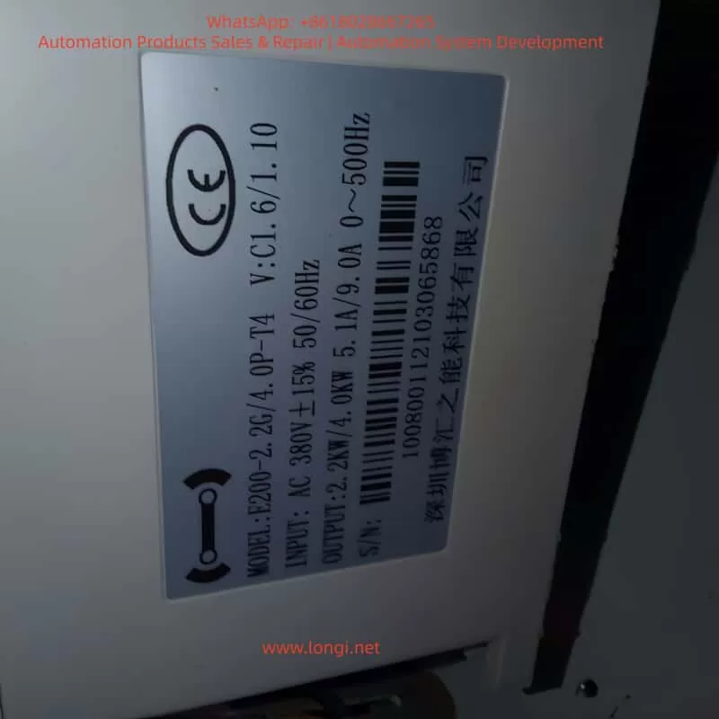
User Guide for Bohui E200 Series Variable Frequency Drive (VFD)

1. Introduction

The Bohui E200 series Variable Frequency Drive (VFD) is a high-performance, reliable vector control inverter widely used in industrial automation, including fans, pumps, textile machinery, machine tools, packaging, and food processing. It supports VF control, open-loop vector control, and closed-loop vector control, and features PLC functionality, PID control, multi-speed operation, and high-speed pulse input.

This guide provides a detailed explanation of the E200 series operation panel, parameter settings, external control wiring, and fault troubleshooting to help users efficiently operate and maintain the device.


2. Operation Panel Overview

Front panel of E200 VFD

2.1 Panel Buttons and Functions

The E200 series VFD operation panel includes the following buttons:

ButtonFunction
RUNStarts the VFD.
STOP/RESETStops the VFD or resets faults.
MODESwitches between parameter setting and monitoring modes.
UP/DOWNAdjusts parameter values or navigates menus.
ENTERConfirms parameter settings or enters submenus.
JOGUsed for jog operation or command source switching.

2.2 Display Screen Functions

The display screen shows real-time data, including:

  • Running frequency
  • Set frequency
  • Bus voltage
  • Output current
  • Fault codes

Users can customize the display content via F0-00 (Menu Mode Selection).


3. Parameter Settings and Management

3.1 Restoring Factory Default Settings

To reset all parameters to factory defaults:

  1. Press MODE to enter parameter setting mode.
  2. Navigate to F0-47 (Parameter Initialization).
  3. Set F0-47 = 1001 to restore factory settings (excluding motor parameters).
  4. Set F0-47 = 1002 to reset recorded information.
  5. Press ENTER to confirm. The VFD will restart automatically.

3.2 Setting and Removing Password Protection

To prevent unauthorized parameter changes, the E200 supports password protection:

Setting a Password

  1. Enter F0-46 (Password Setting).
  2. Set a non-zero value (e.g., 1234).
  3. Confirm with ENTER. The password will be required to access parameters.

Removing a Password

  1. Enter F0-46.
  2. Set the value to 0.
  3. Confirm with ENTER. Password protection will be disabled.

3.3 Parameter Access Restrictions

The E200 allows different access levels via F0-44 (Parameter Access Level):

LevelAccess Permission
0No restrictions.
1Basic parameter modifications only.
2Most parameter modifications allowed.
3Monitoring only (no modifications).
4Fully locked.

Steps to Set Access Level:

  1. Enter F0-44.
  2. Select the desired level (0~4).
  3. Confirm with ENTER.

4. External Terminal Control and Speed Adjustment

4.1 External Terminal Forward/Reverse Control

The E200 supports forward and reverse control via external terminals.

Wiring Terminals

  • X1: Forward run (default function).
  • X2: Reverse run (requires configuration).
  • COM: Common terminal.

Parameter Settings

  1. Enter F5-00 (X1 Input Function Selection) and set to 1 (Forward Run).
  2. Enter F5-01 (X2 Input Function Selection) and set to 2 (Reverse Run).
  3. Ensure F0-02 (Run Command Channel Selection) is set to 1 (Terminal Control).

Wiring Example:

  • Connect an external switch or PLC output to X1 and X2, with COM as the common terminal.

4.2 External Potentiometer Speed Control

The E200 supports speed adjustment via an external potentiometer (010V or 420mA).

Wiring Terminals

  • AI1: Analog input terminal (default 0~10V).
  • +10V: Reference voltage output.
  • ACM: Analog common terminal.

Parameter Settings

  1. Enter F0-03 (Main Frequency Source Selection) and set to 2 (AI1).
  2. Configure F5-24~F5-27 to set the AI1 input range (e.g., 010V corresponds to 050Hz).
  3. Ensure F0-02 (Run Command Channel Selection) is set to 1 (Terminal Control).

Wiring Example:

  • Connect the potentiometer to AI1 and ACM, and use +10V as the reference voltage.

Side (panel/view) of E200 VFD

5. Fault Codes and Troubleshooting

The E200 displays fault codes on the screen or via U0-62 (Current Fault Code). Below are common faults and solutions:

Fault CodeFault NamePossible CauseSolution
OC1Acceleration OvercurrentShort acceleration time, excessive loadIncrease acceleration time (F0-10), check load
OC2Deceleration OvercurrentShort deceleration time, high inertiaIncrease deceleration time (F0-11), add braking resistor
OU1Acceleration OvervoltageHigh supply voltage, insufficient brakingCheck power supply, add braking unit
LUUndervoltage FaultLow supply voltageCheck power supply stability
OL2Motor OverloadMotor overheating, excessive loadCheck motor cooling, reduce load
IPLInput Phase LossMissing input phaseCheck input power wiring
ETFExternal FaultExternal fault signalCheck external control wiring
CoFCommunication FaultCommunication line issueCheck communication interface and wiring

Troubleshooting Steps:

  1. Check U0-62 for the fault code.
  2. Refer to the table above to identify the cause.
  3. Take corrective action.
  4. Press STOP/RESET to clear the fault after resolution.

6. Conclusion

The Bohui E200 series VFD is a powerful and flexible device suitable for various industrial applications. This guide covers operation panel functions, parameter settings, external control wiring, and fault troubleshooting to help users operate the VFD efficiently.

Posted on

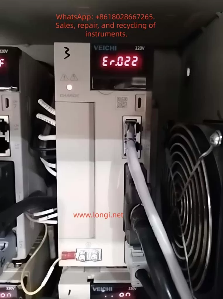
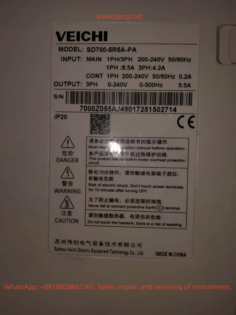
Analysis and Systematic Solutions for ER.022 Fault in Weichuang Servo SD700 Series

Introduction

In the field of modern industrial automation, servo systems are the core components for high-precision motion control, and their stability and reliability directly impact the efficiency and product quality of production lines. The SD700 series servo drives launched by Weichuang Electric have gained market recognition due to their excellent performance and wide applications. However, in actual operation, the ER.022 fault code, as a common system abnormality alert, poses a challenge to technicians. This article will provide a systematic technical guide for technicians from the aspects of definition, causes, diagnosis, solutions, and prevention.

ER.022 fualt

I. Overview of the ER.022 Fault Code

1.1 Definition of the Fault Code

The ER.022 fault code in the Weichuang Servo SD700 series represents a “system and checksum anomaly,” indicating that the servo drive has detected inconsistencies in system parameters, data, or checksums during self-check or operation, which may be caused by software errors, hardware failures, or external interference.

1.2 Fault Phenomena

When the SD700 series servo drive experiences an ER.022 fault, it is usually accompanied by the following phenomena:

  • The fault indicator light on the drive panel illuminates, displaying the ER.022 error code.
  • The servo motor stops running and fails to respond to control commands from the host computer.
  • The drive may automatically enter a protective state.

II. Analysis of the Causes of the ER.022 Fault

2.1 Software Errors

  • Loss or Damage of System Parameters: Parameters may be lost or damaged during storage or transmission due to sudden power outages or electromagnetic interference.
  • Incompatibility of Firmware Versions: The firmware may be incompatible with the host computer software or other devices.
  • Software Defects: The servo drive software may have undiscovered defects or vulnerabilities.

2.2 Hardware Failures

  • Memory Failures: Non-volatile memories such as EEPROMs and Flash memories may age, be damaged, or have write errors.
  • Processor Failures: The CPU or DSP may operate abnormally due to overheating, voltage instability, or manufacturing defects.
  • Communication Interface Failures: Data transmission errors may occur due to poor contact, damage, or protocol mismatches in communication lines.

2.3 External Interference

  • Electromagnetic Interference: Electromagnetic interference may be generated by frequency converters, high-voltage cables, etc., in the surrounding environment.
  • Power Supply Fluctuations: Unstable power supplies may cause abnormal operation of internal circuits in the drive, such as voltage dips or surges.
SD700 weichi drive

III. Diagnostic Process for the ER.022 Fault

3.1 Preliminary Checks

  • Confirm Fault Phenomena: Check the fault indicator light and error code on the drive panel.
  • Check Power Supply: Use a multimeter to measure the input power supply voltage to ensure it is stable without fluctuations.
  • Check Communication Lines: Check the connection status of communication lines to ensure there are no loose or damaged parts.

3.2 In-Depth Diagnosis

  • View Fault Logs: View fault logs through the host computer software or drive panel.
  • Parameter Backup and Restoration: Back up parameters and then perform initialization operations to restore factory settings. Reconfigure parameters and observe whether the fault disappears.
  • Firmware Upgrade: Check and upgrade the firmware version.
  • Hardware Detection: Use professional testing tools to detect key components such as memories, processors, and communication interfaces.

IV. Solutions for the ER.022 Fault

4.1 Software Solutions

  • Parameter Initialization and Reconfiguration:
    • Back up parameters to an external storage device.
    • Perform initialization operations to restore factory settings.
    • Reconfigure parameters according to requirements and observe whether the fault disappears.
  • Firmware Upgrade:
    • Download the latest firmware file from the official website.
    • Burn the firmware using the host computer software or a dedicated programmer.
    • Restart the drive and observe whether the fault disappears.

4.2 Hardware Solutions

  • Replace Memory: If memory failure is suspected, try replacing the EEPROM or Flash memory and reconfigure parameters.
  • Replace Processor: If processor failure is confirmed, replace the entire drive or processor module and reconfigure parameters and upgrade the firmware.
  • Repair Communication Interface: Check the connection status of communication lines and replace the communication interface module or the entire drive.

4.3 Solutions for External Interference

  • Electromagnetic Shielding: Perform electromagnetic shielding treatment on the drive and surrounding equipment and use shielded cables for connections.
  • Stable Power Supply: Provide a stable and reliable power supply and use a UPS or voltage regulator to ensure power quality.

V. Preventive Measures and Routine Maintenance

5.1 Preventive Measures

  • Regular Parameter Backup: Regularly back up parameters for quick restoration.
  • Avoid Sudden Power Outages: Avoid sudden power outages during operation as much as possible.
  • Use Genuine Software: Ensure that genuine software and firmware from the official source are used.

5.2 Routine Maintenance

  • Cleaning and Dust Prevention: Regularly clean the drive and surrounding equipment to keep them clean and well-ventilated.
  • Check Connection Lines: Regularly check whether connection lines are properly connected without looseness or damage.
  • Monitor Operating Status: Monitor the operating status and parameter changes of the drive through the host computer software or drive panel to promptly detect and handle potential problems.

VI. Conclusion

The ER.022 fault, as a common system abnormality alert in the Weichuang Servo SD700 series, has causes involving software errors, hardware failures, and external interference. Through a systematic diagnostic process and solutions, technicians can effectively locate and solve the problem to ensure the stable operation of the servo system. Meanwhile, taking preventive measures and strengthening routine maintenance can reduce the probability of fault occurrence and improve the efficiency and product quality of production lines.

Posted on

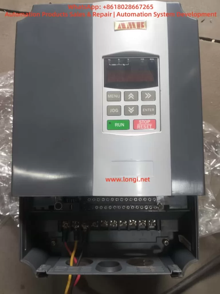
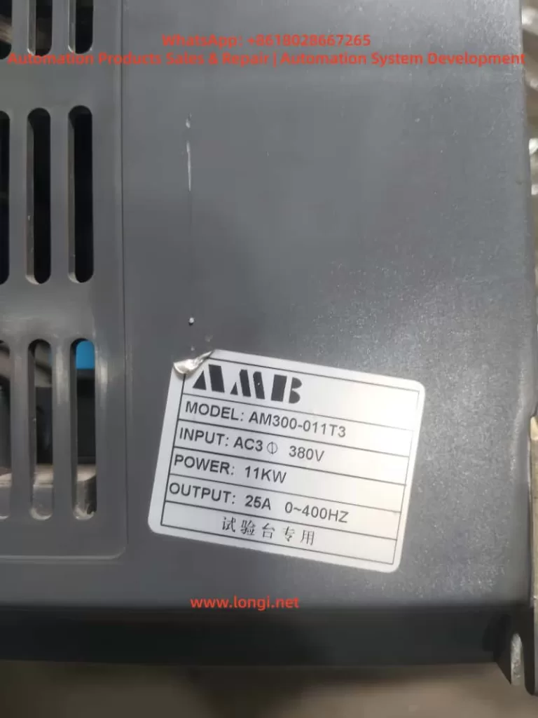
User Guide for AMB300 Series of Ampower Inverters

Introduction

The AMB300 series of Ampower inverters are high-performance, multifunctional inverters widely used in the field of industrial automation. This article will provide a detailed introduction to the operation panel functions, password setting and removal, parameter access restrictions, setting parameters back to factory defaults, as well as how to achieve external terminal forward/reverse rotation control and external potentiometer speed regulation for this series of inverters. Additionally, it will explore common fault codes and their solutions to help users better use and maintain the AMB300 series inverters.

Front-view image of AM300 VFD

I. Introduction to Operation Panel Functions

1.1 Overview of the Operation Panel

The operation panel of the AMB300 series inverters integrates functional modules such as a five-digit LED digital tube monitor, light-emitting diode (LED) indicators, and operation buttons, providing an intuitive operation interface and rich display information.

1.2 Functions of Operation Buttons

  • RUN Button: Starts the inverter operation.
  • STOP/RESET Button: Stops the inverter operation or resets faults.
  • Shift Buttons (<< and >>): Used for shifting operations during parameter setting, as well as for switching between operation monitoring and fault monitoring displays.
  • Increase (▲) and Decrease (▼) Buttons: Used for increasing or decreasing numerical values during parameter setting.
  • OK Button: Confirms parameter settings or enters the next-level menu.
  • MENU Button: Programming/exit button, used to enter or exit the programming state.
  • JOG Button: Jog operation button, used for jog operation or multifunctional operations.

1.3 Display Information

The operation panel displays function codes, set parameters, operating parameters, and fault information through the LED digital tube. Users can view different display contents using the shift buttons and the increase/decrease buttons.

II. Password Setting and Removal

2.1 Password Setting

To protect the inverter parameters from being arbitrarily modified, users can set a user password.

  • Enter Programming State: Press the MENU button to enter the programming state.
  • Select Parameter: Use the shift buttons and the increase/decrease buttons to locate the F7.00 (User Password) parameter.
  • Set Password: Input the desired password (any number between 0 and 65535) using the increase/decrease buttons.
  • Confirm Setting: Press the OK button to save the password setting.

2.2 Password Removal

To remove an already set password, follow these steps:

  • Enter Programming State: Press the MENU button to enter the programming state.
  • Select Parameter: Use the shift buttons and the increase/decrease buttons to locate the F7.00 (User Password) parameter.
  • Clear Password: Set the password value to 0.
  • Confirm Setting: Press the OK button to save the setting, and the password protection function will be disabled.
Side-view image of AM300 VFD

III. Parameter Access Restrictions

To prevent unauthorized personnel from modifying key parameters, the AMB300 series inverters provide a parameter access restriction function.

  • Enter Programming State: Press the MENU button to enter the programming state.
  • Select Parameter Group: Use the shift buttons and the increase/decrease buttons to locate the parameter group for which access restrictions are to be set.
  • Set Access Permissions: Set access permissions (such as read-only or requiring a password for access) through relevant parameters (such as an unspecified parameter beside the F7.01 LCD Display Language Selection, but there is usually a similar function).
  • Confirm Setting: Press the OK button to save the setting.

IV. Setting Parameters Back to Factory Defaults

If you need to restore the inverter parameters to their factory default values, follow these steps:

  • Enter Programming State: Press the MENU button to enter the programming state.
  • Select Restore Factory Defaults Parameter: Use the shift buttons and the increase/decrease buttons to locate the F0.12 (Restore Factory Defaults) parameter.
  • Set Restore Option: Set F0.12 to 1 (Restore Factory Defaults) or 2 (Clear Fault Records, depending on the model).
  • Confirm Setting: Press the OK button, and the inverter will begin restoring the factory default settings and automatically restart upon completion.

V. External Terminal Forward/Reverse Rotation Control

5.1 Wiring Method

To achieve external terminal forward/reverse rotation control, the forward (FWD) and reverse (REV) control terminals need to be connected to an external control circuit.

  • Confirm Terminal Positions: Locate the FWD and REV terminals on the inverter’s control loop terminal block.
  • Connect Control Signals: Connect the forward and reverse rotation signals from the external control circuit to the FWD and REV terminals, respectively.
  • Connect Common Terminal: Connect the common terminal (COM) of the FWD and REV terminals to the common ground of the external control circuit.

5.2 Parameter Settings

To make the external terminal forward/reverse rotation control effective, the following parameter settings are required:

  • Operation Command Selection: Set F0.04 (Operation Command Selection) to 1 (Terminal Command Channel).
  • Forward/Reverse Terminal Functions: Ensure that at least one of the X1-X6 multifunctional terminals is set to the forward (FWD) and reverse (REV) functions (set through F1.00-F1.05).
  • Other Relevant Parameters: Set parameters such as acceleration time (F0.02) and deceleration time (F0.03) according to actual needs.

VI. External Potentiometer Speed Regulation

6.1 Wiring Method

To achieve external potentiometer speed regulation, the potentiometer needs to be connected to the analog input terminals of the inverter.

  • Confirm Terminal Positions: Locate the AI1 (or AI2) and GND terminals on the inverter’s control loop terminal block.
  • Connect Potentiometer: Connect the two ends of the potentiometer to the AI1 (or AI2) and GND terminals, respectively, with the middle tap serving as the speed regulation signal input.
  • Power Connection: If necessary, provide external power (usually +10V, which can be obtained from the inverter’s control terminal block) for the potentiometer.

6.2 Parameter Settings

To make the external potentiometer speed regulation effective, the following parameter settings are required:

  • Frequency Source Selection: Set F0.05 (Frequency Source Selection) to 1 (Analog AI1 Setting) or 2 (Analog AI2 Setting).
  • Analog Input Range: Set the lower limit value (F1.09/F1.13) and upper limit value (F1.11/F1.17) of AI1 (or AI2) according to the output range of the potentiometer (usually 0-10V or 0-20mA).
  • Other Relevant Parameters: Set parameters such as maximum output frequency (F0.06), upper frequency limit (F0.07), and lower frequency limit (F0.08) according to actual needs.

VII. Fault Codes and Solutions

7.1 Common Fault Codes

The AMB300 series inverters may encounter various faults during operation. Common fault codes and their causes are as follows:

  • E.SC: Drive circuit fault, possibly caused by a short circuit between phases or to ground on the inverter’s three-phase output, a direct connection between the same bridge arms of the power module, or module damage.
  • E.OCA: Acceleration overcurrent, possibly caused by a short circuit on the inverter’s output side, excessive load, or too short an acceleration time.
  • E.OCd: Deceleration overcurrent, possibly caused by too short a deceleration time or excessive regenerative energy from the motor.
  • E.OUA: Acceleration overvoltage, possibly caused by restarting a rotating motor or significant changes in the input power supply.
  • E.LU: Undervoltage, possibly caused by a missing phase in the input power supply or significant changes in the input power supply.
  • E.OL1: Motor overload, possibly caused by inaccurate motor parameters or motor stalling.
  • E.OH1/E.OH2: Module overheating, possibly caused by high ambient temperature, poor ventilation of the inverter, or a faulty cooling fan.

7.2 Solutions

For different fault codes, the following solutions can be adopted:

  • E.SC: Check for short circuits on the inverter’s output side and replace damaged power modules.
  • E.OCA/E.OCd: Extend the acceleration/deceleration time, check if the load is too heavy, and adjust the torque boost setting value.
  • E.OUA: Avoid restarting a stopped motor and check if the input power supply is stable.
  • E.LU: Check if the input power supply is normal and ensure there are no missing phases.
  • E.OL1: Reset the motor parameters and check if the load is abnormal.
  • E.OH1/E.OH2: Improve the ventilation environment, replace the cooling fan, and check the temperature detection circuit.

Conclusion

The AMB300 series of Ampower inverters have been widely used in the field of industrial automation due to their high performance, multifunctionality, and ease of operation. This article has provided a detailed introduction to the operation panel functions, password setting and removal, parameter access restrictions, setting parameters back to factory defaults, as well as how to achieve external terminal forward/reverse rotation control and external potentiometer speed regulation for this series of inverters. Additionally, it has explored common fault codes and their solutions. It is hoped that this article can provide useful reference and guidance for a wide range of users.

Posted on

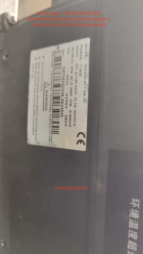
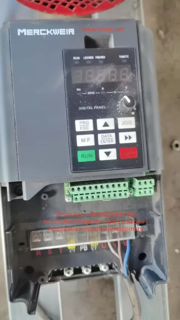
Mericwell Inverter MK300 Instruction Manual Usage Guide

Mericwell Inverter MK300 Instruction Manual Usage Guide

Introduction

The Mericwell MK300 series inverter, as a high-performance vector inverter, is widely applied in various industrial automation scenarios. With its rich functions, stable performance, and flexible control methods, it has gained widespread recognition in the market. This article, based on the official manual of the MK300 inverter, provides a detailed introduction to its operation panel functions, password setting and removal, parameter access restrictions, factory reset, external terminal control, frequency regulation via potentiometer, and solutions to common fault codes, helping users better understand and use this inverter.

I. Operation Panel Function Introduction

1.1 Overview of the Operation Panel

The operation panel of the MK300 inverter integrates multiple function keys and display interfaces, facilitating users in parameter setting, status monitoring, and operation control. The operation panel mainly consists of a multi-function selection key (M.F key), an LED display, function keys (such as the STOP/RESET key), and digital/function selection keys.

1.2 Introduction to Main Function Keys

  • M.F Key: The multi-function selection key is used to switch between different function menus, such as function parameter groups and user-customized parameter groups.
  • STOP/RESET Key: The stop/reset key is used to stop the inverter operation or reset fault conditions.
  • LED Display: It displays the inverter’s running status, parameter values, and fault information, etc.
  • Digital/Function Selection Keys: These keys are used to input numerical values, select functions, or modify parameters.

1.3 Password Setting and Removal

The MK300 inverter offers a password protection function to prevent unauthorized parameter modifications.

Password Setting Steps:

  1. Enter the parameter setting mode: Access the parameter setting menu through the operation panel.
  2. Select the password parameter: Locate parameter PP-00 (User Password Setting) and input the desired password value.
  3. Save the setting: Confirm the password is correct, then save and exit.

Password Removal Steps:

  1. Enter the parameter setting mode: Access the parameter setting menu through the operation panel.
  2. Clear the password parameter: Set the PP-00 parameter value to 0 to remove password protection.
  3. Save the setting: Confirm the change and save.

1.4 Parameter Access Restrictions

The MK300 inverter allows users to set parameter access restrictions to prevent non-authorized personnel from modifying critical parameters.

Setting Steps:

  1. Enter the parameter setting mode: Access the parameter setting menu through the operation panel.
  2. Select the access restriction parameter: Locate parameter PP-03 (Personalized Parameter Group Display Selection) and set the parameter groups that can be displayed and modified according to needs.
  3. Set password protection: For a higher level of protection, combine it with the password setting function to ensure that only users who know the password can modify restricted parameters.

1.5 Factory Reset

When it is necessary to restore all parameters of the inverter to their factory default values, the factory reset function can be used.

Operation Steps:

  1. Enter the parameter setting mode: Access the parameter setting menu through the operation panel.
  2. Select the factory reset parameter: Locate parameter PP-01 (Parameter Initialization) and set it to 1 (restore factory parameters, excluding motor parameters) or 3 (restore factory parameters, including motor parameters).
  3. Confirm and execute: Confirm the operation as prompted, and the inverter will automatically restore to factory settings and restart.

II. External Terminal Control and Frequency Regulation via Potentiometer

2.1 External Terminal Forward/Reverse Rotation Control

The MK300 inverter supports forward/reverse rotation control of the motor through external terminals, offering flexible and convenient practical applications.

Wiring Steps:

  1. Confirm terminal definitions: Refer to the inverter manual to confirm the terminals used for forward/reverse rotation control (e.g., X1, X2).
  2. Connect control signals: Connect external control signals (such as switch signals) to the corresponding terminals, e.g., X1 for forward rotation signals and X2 for reverse rotation signals.
  3. Common ground connection: Ensure that the control signal source and the inverter share a common ground to ensure stable signal transmission.

Parameter Setting Steps:

  1. Enter the parameter setting mode: Access the parameter setting menu through the operation panel.
  2. Set terminal functions: Locate parameters P4-00 (X1 Terminal Function Selection) and P4-01 (X2 Terminal Function Selection) and set them to forward rotation operation and reverse rotation operation, respectively.
  3. Save the setting: Confirm the parameters are correct, then save and exit.

2.2 External Potentiometer Frequency Regulation

The MK300 inverter supports frequency setting through an external potentiometer to achieve motor speed control.

Wiring Steps:

  1. Confirm analog input terminals: Refer to the inverter manual to confirm the terminals used for analog input (e.g., AI1, AI2).
  2. Connect the potentiometer: Connect the two ends of the external potentiometer to the AI1 (or AI2) and GND terminals, respectively, with the middle tap serving as the frequency setting signal.
  3. Common ground connection: Ensure that the potentiometer and the inverter share a common ground to ensure stable signal transmission.

Parameter Setting Steps:

  1. Enter the parameter setting mode: Access the parameter setting menu through the operation panel.
  2. Set the frequency setting source: Locate parameter P0-03 (Main Frequency Source X Selection) and set it to AI1 (or AI2, depending on the actual wiring).
  3. Adjust the input range: According to needs, adjust the input range of AI1 (or AI2) through parameters P4-13 to P4-16 to match the output range of the potentiometer.
  4. Save the setting: Confirm the parameters are correct, then save and exit.

III. Common Fault Codes and Solutions

3.1 Overview of Fault Codes

During the operation of the MK300 inverter, if an abnormal situation is detected, it will display the corresponding fault code through the operation panel and take protective measures. Users need to troubleshoot the cause according to the fault code and take corresponding solutions.

3.2 Common Fault Codes and Solutions

Acceleration Overcurrent (Err02)

Fault Causes:

  • The output circuit of the inverter is grounded or short-circuited.
  • The control mode is vector and parameter identification has not been performed.
  • The acceleration time is too short.
  • The manual torque boost or V/F curve is inappropriate.
  • The voltage is too low.
  • Starting a rotating motor.
  • Sudden load addition during acceleration.
  • The inverter is undersized.

Solutions:

  • Check and eliminate output circuit grounding or short-circuit faults.
  • Perform motor parameter identification.
  • Increase the acceleration time.
  • Adjust the manual torque boost or V/F curve.
  • Adjust the voltage to the normal range.
  • Select speed tracking start or wait for the motor to stop before starting.
  • Cancel sudden load addition.
  • Select an inverter with a higher power rating.

Module Overheating (Err14)

Fault Causes:

  • High ambient temperature.
  • Blocked air duct.
  • Damaged fan.
  • Damaged module thermistor.
  • Damaged inverter module.

Solutions:

  • Lower the ambient temperature.
  • Clean the air duct.
  • Replace the fan.
  • Replace the thermistor.
  • Replace the inverter module.

External Device Fault (Err15)

Fault Causes:

  • An external fault signal is input through the multi-function terminal X.
  • An external fault signal is input through the virtual IO function.

Solutions:

  • Check and reset the external fault signal.
  • Check the virtual IO function settings to ensure they are correct.

Communication Fault (Err16)

Fault Causes:

  • The upper computer is not working properly.
  • The communication line is abnormal.
  • The communication parameter PD group settings are incorrect.

Solutions:

  • Check the upper computer wiring and working status.
  • Check if the communication connection line is normal.
  • Correctly set the communication parameter PD group.

Motor Tuning Fault (Err19)

Fault Causes:

  • The motor parameters are not set according to the nameplate.
  • The parameter identification process times out.

Solutions:

  • Correctly set the motor parameters according to the motor nameplate.
  • Check if the leads from the inverter to the motor are in good condition.

Conclusion

This article has provided a detailed introduction to the operation panel functions, password setting and removal, parameter access restrictions, factory reset, external terminal control, frequency regulation via potentiometer, and solutions to common fault codes of the Mericwell MK300 inverter. Through this introduction, users can better understand and use the MK300 inverter, improving equipment operation efficiency and stability. In practical applications, users should reasonably configure the inverter parameters and functions according to specific needs and scenarios to achieve the best control effect.

Posted on

Comprehensive Guide to Diagnosing and Resolving Overcurrent Faults (E30.4) in Hyundai N700E Inverters


Table of Contents

  1. Introduction
    • The Role of Inverters in Industrial Automation
    • Overview of Hyundai N700E Inverters
    • Importance of Overcurrent Faults
  2. Understanding Overcurrent Faults (E30.4)
    • What Is an Overcurrent Fault?
    • Meaning of the E30.4 Fault Code
    • Overcurrent Protection Mechanisms
  3. Common Causes of E30.4 Faults
    • Overloaded Conditions
    • Incorrect Parameter Settings
    • Power Supply Issues
    • Mechanical Failures
    • Internal Inverter Faults
  4. Diagnostic Steps for E30.4 Faults
    • Using the Digital Operator to View Fault Information
    • Inspecting the Motor and Load
    • Checking Power Supply and Wiring
    • Reviewing Inverter Parameters
    • Inspecting Inverter Hardware
  5. Solutions for E30.4 Faults
    • Adjusting Acceleration Time
    • Optimizing Motor Parameters
    • Addressing Power Supply Issues
    • Fixing Mechanical Failures
    • Repairing or Replacing Inverter Hardware
  6. Preventive Measures for E30.4 Faults
    • Regular Maintenance and Inspections
    • Correct Parameter Configuration
    • Using High-Quality Power Supplies and Wiring
    • Monitoring Load and Environmental Conditions
  7. Advanced Diagnostics and Tools
    • Using Oscilloscopes and Multimeters
    • Leveraging Communication Features of N700E Inverters
    • Analyzing Fault Logs
  8. Case Studies
    • Case Study 1: Overloaded Condition Causing E30.4 Fault
    • Case Study 2: Incorrect Parameter Settings Causing E30.4 Fault
    • Case Study 3: Unstable Power Supply Causing E30.4 Fault
  9. Conclusion and Recommendations
    • Summary of E30.4 Fault Diagnosis and Solutions
    • Best Practices
    • Resources for Further Learning

1. Introduction

1.1 The Role of Inverters in Industrial Automation

Inverters, also known as Variable Frequency Drives (VFDs), are essential components in modern industrial automation systems. They regulate the speed of electric motors by adjusting the frequency and voltage of the power supplied to the motor. This capability enhances energy efficiency, reduces operational costs, and extends the lifespan of equipment. Inverters are widely used in applications such as fans, pumps, conveyors, and machine tools, where precise control of motor speed is critical.

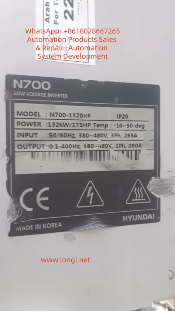
1.2 Overview of Hyundai N700E Inverters

The Hyundai N700E series inverters are high-performance devices designed for industrial applications. Key features include:

  • Energy Efficiency: Advanced control algorithms optimize motor performance.
  • Versatility: Supports multiple control modes, including V/F control and sensorless vector control.
  • Reliability: Built-in protection features such as overcurrent, overload, overvoltage, and undervoltage protection.
  • User-Friendly Interface: Equipped with a digital operator for easy parameter configuration and fault diagnosis.

The N700E series is widely used in industrial settings, including fans, pumps, compressors, and other machinery.

1.3 Importance of Overcurrent Faults

Overcurrent faults are among the most common issues encountered in inverter operations. If not addressed promptly, they can lead to equipment damage, production downtime, and safety hazards. Understanding the causes, diagnostic methods, and solutions for overcurrent faults is crucial for maintenance personnel and engineers.


2. Understanding Overcurrent Faults (E30.4)

2.1 What Is an Overcurrent Fault?

An overcurrent fault occurs when the output current of an inverter exceeds its rated value or the set protection limit. This triggers the inverter’s protection mechanism, causing it to shut down to prevent damage. Overcurrent faults can be caused by various factors, including excessive loads, incorrect parameter settings, and power supply issues.

2.2 Meaning of the E30.4 Fault Code

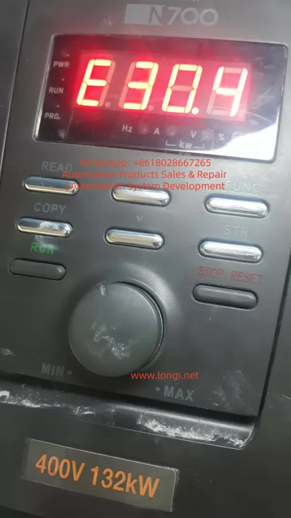
In Hyundai N700E inverters, the E30.4 fault code indicates an overcurrent condition. When this code appears, it means the inverter has detected an output current exceeding the preset protection limit. Immediate action is required to diagnose and resolve the issue.

2.3 Overcurrent Protection Mechanisms

Hyundai N700E inverters are equipped with multiple protection mechanisms to prevent damage from overcurrent conditions:

  • Hardware Protection: Current sensors monitor the output current in real-time. If the current exceeds the limit, the inverter cuts off the output.
  • Software Protection: Parameters can be adjusted to set the sensitivity and response time of the overcurrent protection.

3. Common Causes of E30.4 Faults

3.1 Overloaded Conditions

  • Mechanical Jamming: The motor or mechanical load may be jammed, causing a sudden increase in current.
  • Excessive Load: The motor may be operating under an excessive load for an extended period, leading to current levels beyond the inverter’s rating.

3.2 Incorrect Parameter Settings

  • Short Acceleration Time: The acceleration time (A02) may be set too short, resulting in high starting currents.
  • Incorrect Motor Parameters: The inverter’s motor parameters, such as rated current, power, and pole count, may not match the actual motor specifications.

3.3 Power Supply Issues

  • Voltage Instability: The input voltage may fluctuate excessively or be too low.
  • Phase Loss or Imbalance: A missing phase or voltage imbalance in the three-phase power supply can cause abnormal current levels.

3.4 Mechanical Failures

  • Bearing Damage: Worn or damaged motor bearings can increase friction, leading to higher current draw.
  • Transmission System Failures: Issues with belts, gears, or other transmission components can cause mechanical stress and increased current.

3.5 Internal Inverter Faults

  • Aging Power Modules: The power modules or capacitors may degrade over time, leading to failures.
  • Poor Cooling: Inadequate cooling due to fan failure or dust accumulation can cause overheating and trigger overcurrent protection.

4. Diagnostic Steps for E30.4 Faults

4.1 Using the Digital Operator to View Fault Information

  • Access the d13 (Trip event monitor) mode on the digital operator to view the current, frequency, and other data at the time of the fault.
  • Check d14-d16 (Trip history) to review past fault records.

4.2 Inspecting the Motor and Load

  • Verify that the motor and mechanical load are operating normally, without jamming or abnormal resistance.
  • Inspect transmission components (belts, gears, bearings) for damage or obstructions.

4.3 Checking Power Supply and Wiring

  • Use a multimeter to measure the input voltage (R, S, T) and ensure it is balanced and within the acceptable range.
  • Check for loose or poorly connected wiring terminals.

4.4 Reviewing Inverter Parameters

  • Confirm that parameters such as acceleration time (A02) and motor rated current (A06) are correctly set.
  • Review overload protection levels (b07) to ensure they are appropriately configured.

4.5 Inspecting Inverter Hardware

  • Ensure the cooling fan is operating correctly and the heat sink is free of dust and debris.
  • Inspect power modules and capacitors for signs of damage, such as burning, bulging, or leakage.

5. Solutions for E30.4 Faults

5.1 Adjusting Acceleration Time

  • Increase the acceleration time (F02) to reduce the starting current.

5.2 Optimizing Motor Parameters

  • Ensure the inverter’s motor parameters (rated current, power, pole count) match the actual motor specifications.

5.3 Addressing Power Supply Issues

  • Stabilize the input voltage and ensure it is balanced across all three phases.
  • Use voltage regulators or filters to improve power quality.

5.4 Fixing Mechanical Failures

  • Repair or replace damaged bearings, belts, gears, or other mechanical components.

5.5 Repairing or Replacing Inverter Hardware

  • Replace faulty power modules or capacitors.
  • Clean the heat sink to ensure proper cooling.

6. Preventive Measures for E30.4 Faults

6.1 Regular Maintenance and Inspections

  • Conduct regular inspections of motors and mechanical loads.
  • Clean the inverter’s heat sink and cooling fan periodically.

6.2 Correct Parameter Configuration

  • Configure inverter parameters accurately based on the motor and load specifications.

6.3 Using High-Quality Power Supplies and Wiring

  • Ensure a stable power supply and secure wiring connections.

6.4 Monitoring Load and Environmental Conditions

  • Avoid prolonged operation under overloaded conditions.
  • Ensure the inverter operates in a suitable environment (temperature, humidity, dust-free).

7. Advanced Diagnostics and Tools

7.1 Using Oscilloscopes and Multimeters

  • Use an oscilloscope to monitor current and voltage waveforms for diagnosing power supply and load issues.
  • Use a multimeter to measure voltage, current, and resistance.

7.2 Leveraging Communication Features of N700E Inverters

  • Utilize the RS485 communication interface to transmit inverter data to a computer for remote monitoring and diagnostics.

7.3 Analyzing Fault Logs

  • Analyze the inverter’s fault logs to identify patterns and root causes of faults.

8. Case Studies

8.1 Case Study 1: Overloaded Condition Causing E30.4 Fault

  • Problem: A fan frequently experienced E30.4 faults during startup.
  • Diagnosis: Inspection revealed a jammed fan impeller.
  • Solution: Cleaning the impeller and lubricating the bearings resolved the issue.

8.2 Case Study 2: Incorrect Parameter Settings Causing E30.4 Fault

  • Problem: A pump inverter displayed E30.4 faults during startup.
  • Diagnosis: The acceleration time (A02) was set too short.
  • Solution: Increasing the acceleration time eliminated the fault.

8.3 Case Study 3: Unstable Power Supply Causing E30.4 Fault

  • Problem: A conveyor inverter experienced sudden E30.4 faults during operation.
  • Diagnosis: The input voltage was found to be highly unstable.
  • Solution: Installing a voltage regulator resolved the issue.

9. Conclusion and Recommendations

9.1 Summary of E30.4 Fault Diagnosis and Solutions

E30.4 faults are typically caused by overloaded conditions, incorrect parameter settings, or power supply issues. Systematic diagnostic steps can quickly identify the root cause and implement appropriate solutions.

9.2 Best Practices

  • Perform regular maintenance and inspections of inverters and motors.
  • Configure inverter parameters accurately.
  • Use high-quality power supplies and wiring.
  • Monitor load and environmental conditions.

9.3 Resources for Further Learning

  • Hyundai N700E Inverter User Manual
  • Training courses on inverter maintenance and fault diagnosis
  • Professional technical forums and communities

Appendix: Common Fault Code Table

Fault CodeFault TypePossible CausesSolutions
E30.4OvercurrentOverloaded conditions, incorrect parameters, power supply issuesAdjust parameters, check load, repair power supply

This article provides a comprehensive guide to diagnosing and resolving E30.4 overcurrent faults in Hyundai N700E inverters. It is designed for engineers and maintenance personnel to better understand and address this common issue.

Posted on

User Guide for the Xintian NSD-A/P Series Frequency Converter Manual

Introduction

The Xintian NSD-A/P series frequency converter is a high-performance, low-voltage, multi-functional device suitable for industrial applications ranging from 0.4 kW to 560 kW. This series supports vector control and V/F control, and is equipped with advanced PLC function interfaces and various communication protocols, such as RS485/Modbus. It is an ideal choice for modern industrial equipment. This document provides a detailed introduction to the operation panel functions, parameter settings, external control, and troubleshooting methods to help users safely and efficiently utilize the equipment.

Part 1: Introduction to Operation Panel Functions

Basic Structure of the Operation Panel

  • LED Display: Shows output frequency, current, voltage, or fault codes. For example, in running mode, it defaults to displaying the current frequency, such as “50.00” indicating 50 Hz.
  • Status Indicators: Include DRV, FREF, FOUT, IOUT, FWD, REV, etc., used for quickly determining the status of the frequency converter.

Key Functions

  • PRG (Program Key): Enters the parameter setting mode. Press and hold to return to the previous menu.
  • ENTER (Confirm Key): Confirms selections or saves parameter modifications.
  • UP/DOWN (Up/Down Keys): Increases or decreases parameter values and scrolls through menus.
  • FWD/REV (Forward/Reverse Keys): Initiates forward or reverse operation.
  • STOP/RESET (Stop/Reset Key): Stops operation or resets faults.

Parameter Initialization

  1. Ensure the frequency converter is stopped, then press the PRG key to enter the parameter setting mode.
  2. Navigate to F0.02 (Initialize Parameters), set it to 1, and press ENTER to confirm.
  3. The frequency converter will flash “INIT” as a prompt. Initialization is complete when it automatically resets.

Password Setting and Removal

  • Setting a Password: Enter F0.00, set a 4-digit password, and press ENTER to save.
  • Removing a Password: Enter the correct password to unlock, then set F0.00 to 0 and press ENTER to save.

Parameter Access Restrictions

  1. Enter F0.01 and set the access level (0 for full access, 1 for basic parameters, 2 for advanced parameters).
  2. Press ENTER to save.

Part 2: External Terminal Forward/Reverse Control and External Potentiometer Speed Adjustment

External Terminal Forward/Reverse Control

  • Wiring: Connect the FWD terminal to one end of a switch, and the other end of the switch to COM. Connect the REV terminal to one end of another switch, and the other end of that switch to COM.
  • Parameter Settings:
    • Set F2.00 to 1 (External Terminal Control).
    • Set F2.01 to 1 (Two-Wire Control Mode 1).
  • Power-On Test: Close the FWD switch for forward motor rotation, and close the REV switch for reverse motor rotation.

External Potentiometer Speed Adjustment

  • Wiring: Connect one end of the potentiometer to +10V, the middle tap to AI1, and the other end to GND.
  • Parameter Settings:
    • Set F0.01 to 2 (Analog AI1 Speed Adjustment).
    • Set F0.02 to 0.10s (Analog Input Filtering).
    • Set F0.03 and F0.04 to the minimum and maximum frequencies, respectively.
  • Operation: Rotate the potentiometer while powered on to adjust the frequency.

Part 3: Frequency Converter Fault Codes and Solutions

Common Fault Codes and Solutions

Fault CodeDescriptionPossible CausesSolutions
E.01OvercurrentOverloaded, too short acceleration timeExtend acceleration time, check motor insulation
E.02OvervoltageToo short deceleration time, brake resistor failureExtend deceleration time, install brake resistor
E.03UndervoltageLow grid voltage, loose power linesCheck input voltage, tighten connections
E.04OverheatingFan failure, high ambient temperatureClean fan, reduce ambient temperature
E.05Motor OverloadLoad exceeds rated value, incorrect parameter settingsAdjust motor protection parameters, reduce load
E.06PID FaultPID feedback signal lostCheck PID parameters, inspect sensor wiring
E.07Communication FaultLoose RS485 wiresCheck RS485 connections, confirm Modbus parameters
E.08External FaultExternal terminal input signalCheck S1-S6 terminals, clear external signal sources
E.09Internal FaultControl board issueReset; if ineffective, contact the manufacturer for repair
E.10EEPROM FaultParameter storage errorInitialize parameters, back up data and reset

General Fault Resolution Process

  1. When a fault occurs, the panel displays the fault code, and the motor stops.
  2. Press STOP/RESET to reset. If ineffective, power off for 5 minutes and try again.
  3. Check the fault history and determine the cause based on the code.
  4. Adjust parameters or inspect hardware, then test operation.

Conclusion

The Xintian NSD-A/P series frequency converter, with its powerful features and user-friendly design, is an excellent choice for industrial control. Through this guide, users can master the operation panel, parameter management, external control, and fault diagnosis. In practical applications, optimize parameters according to site conditions, such as using PID in pump systems to achieve constant pressure water supply, saving over 30% in energy. This manual emphasizes safety first; read all warnings before operating. For more advanced applications, such as Modbus communication or multi-speed settings, refer to the parameter table for expansion.