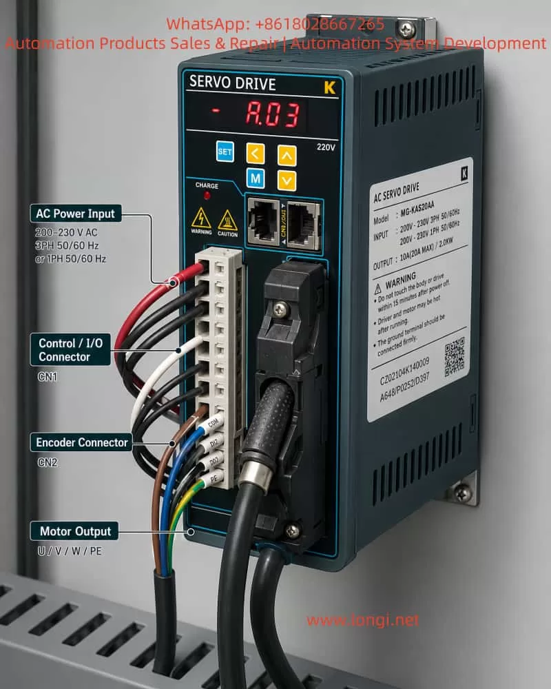
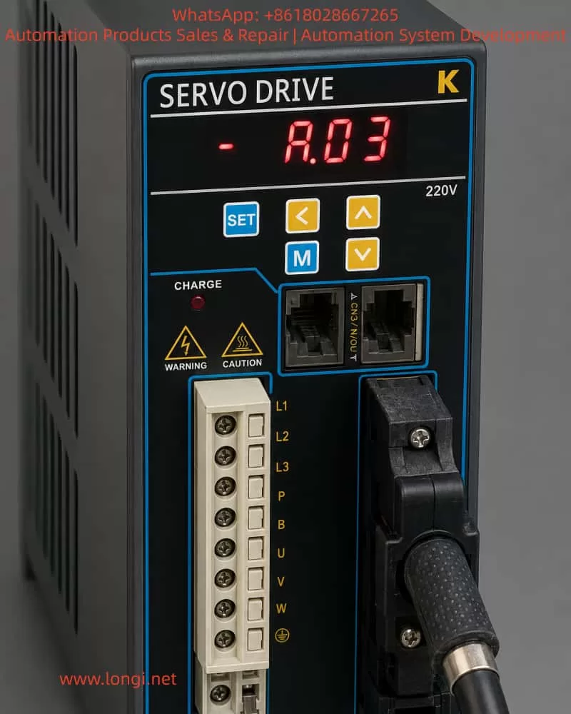
In industrial automation, servo drives are essential for precise control of position, speed, and torque. Based on user reports and inspection images (Attachments 1 and 2), the MG-KAS20AA K-series AC servo drive exhibits the “A.03” alarm code. This code appears on the front panel digital display (Image 2), and the drive fails to rotate, halting the connected mechanical load.
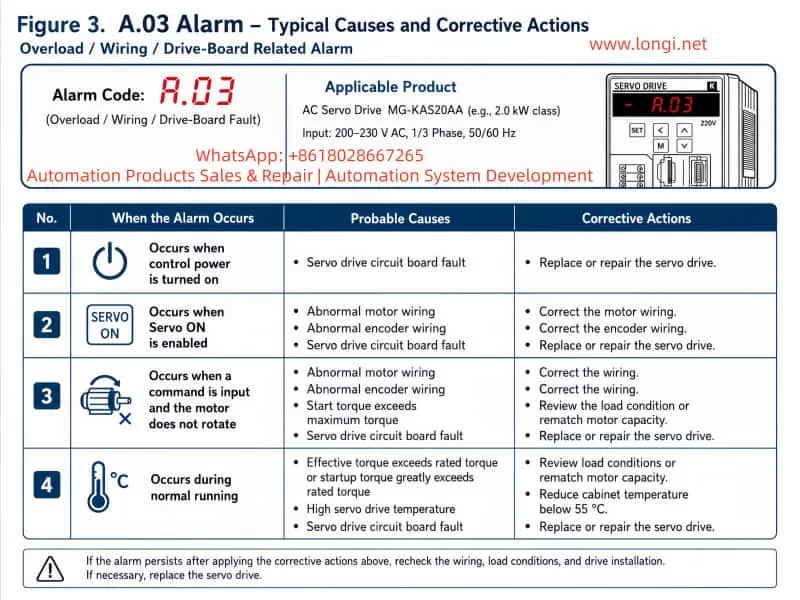
According to the K Series AC Servo Drive User Manual (2017 Engineer Edition V3.0), Chapter 7 and Appendix C, the A.03 alarm falls under overload/torque anomaly faults, primarily associated with:
Servo drive circuit board faults
Motor wiring issues
Encoder signal errors
Load torque exceeding the drive’s limits
Images show U/V/W motor terminals correctly connected, CN1/CN2 encoder interfaces installed, and PE properly grounded, yet the A.03 alarm persists. This indicates the fault is likely related to the drive board or signal compatibility rather than simple wiring issues.
2. Fault Trigger Conditions
Based on the manual, A.03 may be triggered in the following scenarios:
Scenario
Trigger Condition
Possible Cause
Recommended Action
Servo ON
Motor does not rotate
Motor wiring abnormality, encoder wiring issue
Inspect and correct motor and encoder wiring
Command input
Servo motor unresponsive
Start-up torque exceeds maximum
Adjust load conditions or re-evaluate motor capacity
Normal operation
Drive reports A.03
High internal temperature of servo drive
Reduce drive temperature below 55℃, verify cooling system
Any operation
Drive board fault
Drive power module or control board malfunction
Replace servo drive or repair circuit board
Given the images, the drive reports A.03 under normal power and command input. Hence, drive board or power module failure is the primary suspected cause.
3. Detailed Fault Diagnosis Steps
3.1 Visual Inspection and Wiring Verification
Power Check
Verify L1/L2/L3 terminals receive 220V three-phase within ±15%.
Confirm L1C/L2C control voltage is stable.
Motor Wiring
U/V/W terminals correspond to the drive terminals.
Measure resistance across phases; check for open or short circuits.
Grounding and Shielding
PE terminals connected to drive, motor, and cabinet.
Encoder shield connected to the chassis.
3.2 Encoder Signal Check
Per Manual Section 3.4:
CN1: Axis A encoder
CN2: Axis B encoder
Procedure:
Measure A/B phase signals with an oscilloscope.
Verify PG pulse output matches user parameter settings.
Ensure IN1~IN8 input allocation (P□509~P□512) is correct.
Confirm wiring length and shield integrity (max 3m for command input, max 20m for feedback).
Faulty encoder signals may mislead the drive’s load detection and trigger A.03.
3.3 Drive Board and Power Module Inspection
Manual 7.2.3 highlights common failure points:
Power Modules (IGBTs/MOSFETs)
Shorted or open MOSFETs can trigger overcurrent protection (A.03).
Use infrared thermometer to monitor PCB temperature (<55℃).
Control Board
MCU or logic faults may prevent overload signal processing.
Check for burnt components or swollen capacitors; replace control board if needed.
3.4 Load Evaluation
A.03 may also result from excessive load torque:
Load inertia exceeding 5× motor inertia.
Mechanical resistance or over-torque beyond rated motor torque.
Aggressive start/stop conditions causing current peaks.
Mitigation:
Inspect load bearings and couplings for jamming.
Measure mechanical torque against motor rating.
Adjust dynamic braking or P-OT / N-OT limit parameters.
3.5 Software and Parameter Verification
Check user parameters P□□□: torque limit, load inertia, and travel limits.
Confirm control mode (position/speed/torque) matches mechanical load.
For absolute encoders, ensure F□009/F□010 settings are correct.
4. Fault Handling and Recovery
Immediate Measures
Power down for at least 15 minutes to discharge capacitors.
Inspect cooling and airflow.
Wiring and Encoder Verification
Cross-check terminals per manual 3.1–3.4.
Confirm encoder signals via oscilloscope.
Circuit Board or Module Maintenance
If wiring and encoder are correct, replace power modules or control board.
Alternatively, send to manufacturer for repair.
Parameter and Load Adjustment
Ensure user parameters are within safe limits.
Adjust load or enable torque compensation to reduce peak currents.
Long-term Protection
Maintain drive environment below 45℃.
Avoid high humidity, dust, or corrosive gases.
Ensure proper PE grounding.
Inspect encoder and motor connections periodically.
5. Conclusion
The A.03 alarm on K-series AC servo drives indicates overload/torque anomaly, caused by:
Drive board or power module failure
Motor wiring or encoder signal issues
Load exceeding motor capacity
Overheating or insufficient cooling
Resolution Principle:
Inspect wiring and connections first.
Verify encoder signals and input/output parameter allocation.
Evaluate load and mechanical conditions.
Replace drive board or power module if necessary.
Following this systematic approach ensures reliable operation of MG-KAS20AA drives, minimizing downtime and safeguarding industrial automation processes.
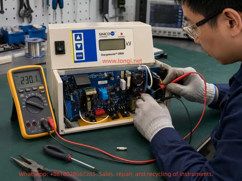
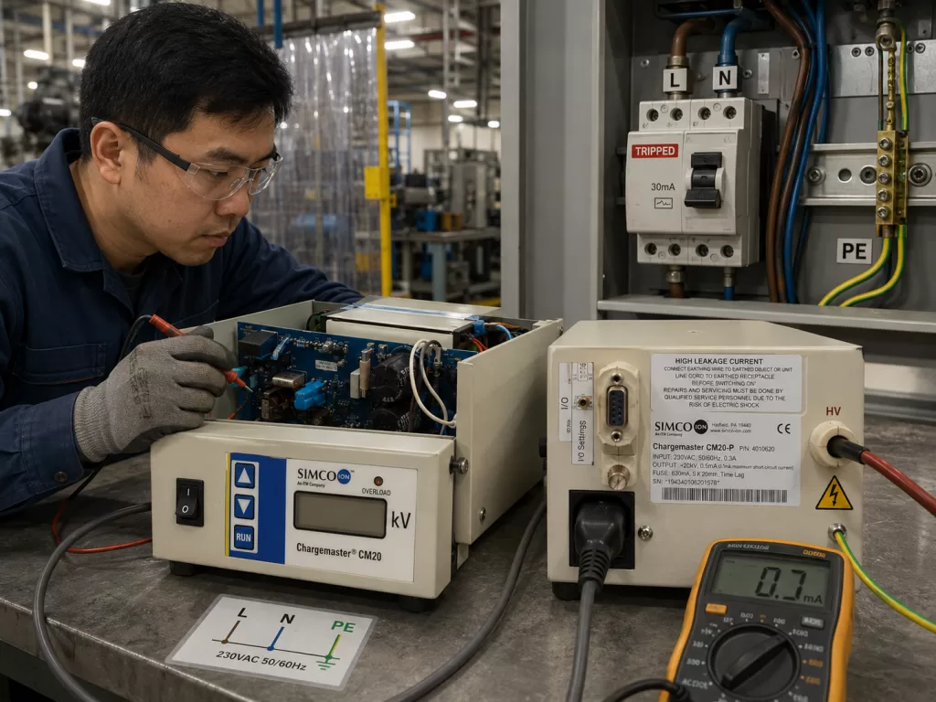
The SIMCO-ION Chargemaster CM20-P is an industrial electrostatic high-voltage generator. It is commonly used in electrostatic charging, electrostatic adhesion, film processing, printing and packaging, plastic sheet handling, lamination systems, and automated production lines. Its main function is to convert a standard AC input supply into a high-voltage DC output, which is then supplied to static bars, electrodes, charging heads, or electrostatic holding devices.
According to the nameplate, the main specifications of this unit are:
Item
Specification
Brand
SIMCO-ION
Model
Chargemaster CM20-P
Input Power
230VAC, 50/60Hz
Input Current
0.3A
Output Voltage
+20kV
Output Current
0.5mA
Fuse
630mA, 5×20mm, Time Lag
Although the input power of this type of equipment is not high, the output voltage reaches +20kV. It is a typical low-current, high-voltage device. Such equipment is very sensitive to grounding, insulation condition, humidity, contamination, high-voltage cable condition, static bar cleanliness, and electrode-to-metal distance.
Once leakage, discharge, short circuit, or insulation breakdown occurs at the high-voltage output side, the unit may show symptoms such as OVERLOAD alarm, blown fuse, leakage breaker tripping, no output, abnormal display, or unstable operation.
In this case, the fault development was very typical:
At the beginning, the OVERLOAD red indicator on the front panel was lit. This usually means that the high-voltage output was abnormal or the load was excessive. Later, inspection found that an internal fuse had blown. After replacing the fuse, the main display powered on, and the OVERLOAD red light was no longer lit. However, a new fault appeared: the breaker tripped when the unit was powered on.
The customer also reported that when the equipment was used inside the factory, the breaker tripped as soon as the earth wire was connected. The site power system was described as three-phase four-wire.
These pieces of information indicate that the fault is not simply a blown fuse or a grounding question. It involves several possible fault directions, including high-voltage output overload, internal power circuit short circuit, leakage to ground, and improper site grounding system. The troubleshooting must be carried out systematically from four aspects: input power, protective earth, high-voltage output, and internal components.
2. Meaning of the OVERLOAD Indicator
The OVERLOAD indicator on an electrostatic high-voltage generator is usually not a general power alarm. It is closely related to the high-voltage output condition. It normally means that the unit cannot establish the required output voltage, or the output current has exceeded the permitted range.
Common causes include:
Short circuit at the high-voltage output;
Internal leakage in the static bar;
Damaged or aged high-voltage cable insulation;
Electrode installed too close to a metal frame;
Dust, oil, moisture, or contamination causing surface creepage;
Internal breakdown of the high-voltage module;
Abnormal high-voltage feedback detection circuit;
Load exceeding the design capacity of the generator.
The CM20-P output is +20kV and 0.5mA. Although the current is very small, in a high-voltage electric field, even slight moisture, dust, oil contamination, burrs, or carbonized tracks can form a leakage path. When the generator detects abnormal output current, it lights the OVERLOAD indicator to warn of output overload or insulation failure.
Therefore, the initial OVERLOAD alarm already indicated that the equipment or its external load had a real fault. The later blown fuse was only a result of the fault progressing further. Replacing the fuse does not mean the equipment has recovered. A blown fuse usually means that the power circuit experienced overcurrent, short circuit, or an abnormal surge.
3. A Blown Fuse Is Usually a Result, Not the Root Cause
When field technicians see a blown fuse, the first reaction is often to replace it. However, in industrial electronic equipment, the fuse itself is rarely the root cause. Its function is protection. If it blows, it means the downstream circuit has drawn abnormal current.
The CM20-P nameplate specifies:
630mA, 5×20mm, Time Lag
This means:
T630mA / 250V / 5×20mm slow-blow fuse
There are two important points here.
First, the fuse rating must not be increased randomly. If the original fuse is 630mA slow-blow, it must not be replaced with a 1A, 2A, or larger fuse simply to prevent it from blowing again. It is even more dangerous to use copper wire instead of a fuse. This may keep the circuit powered temporarily, but it can cause more serious damage to components, PCB traces, transformers, high-voltage modules, or even create a fire and electric shock hazard.
Second, fast-blow and slow-blow fuses must not be used interchangeably without analysis. When the equipment starts, there may be short-duration inrush current from filter capacitor charging, transformer magnetizing current, or high-voltage circuit startup. A slow-blow fuse is designed to tolerate this short inrush. If a fast-blow fuse is installed incorrectly, it may blow even during normal startup.
However, if the correct slow-blow fuse is installed and the breaker still trips or the fuse blows again, the downstream circuit must be checked. Repeated power-on testing is not acceptable.
In this case, after the fuse was replaced, the display could light up, proving that part of the low-voltage supply had recovered. But the subsequent breaker tripping proves that the root fault remained. Replacing the fuse merely restored the current path. The real short circuit, leakage, or high-voltage insulation fault was still present.
4. Breaker Tripping: MCB Trip or RCD/RCBO Trip?
When a customer says “the breaker trips,” the first task is to identify what type of protection device is tripping. Different protection devices indicate different fault directions.
If an ordinary MCB trips, the main concern is overcurrent or short circuit. Typical causes include L-N short circuit, shorted rectifier bridge, shorted main electrolytic capacitor, shorted power transistor, or shorted transformer primary winding.
If an RCD or RCBO trips, the main concern is earth leakage. Typical causes include leakage in the input filter, abnormal Y capacitor, high-voltage circuit breakdown to chassis, moisture or carbonization at the output socket, damaged high-voltage cable, or incorrect N/PE connection on site.
In this case, the customer’s photo showed a CHINT NXBLE-63 C63 breaker. The NXBLE-63 is a leakage-protection circuit breaker, commonly known as an RCBO. It can trip because of earth leakage, but it can also trip because of overload or short circuit. Therefore, its tripping does not automatically prove that the fault is purely earth leakage. However, it does prove that the equipment caused an abnormal condition at power-up.
The fault must be further divided into the following situations.
4.1 The Breaker Trips Immediately When the Plug Is Inserted with the Power Switch OFF
If the front power switch of the unit is OFF, but the breaker trips immediately when the power plug is inserted, the fault is usually located before the main power switch.
The key areas to check are:
Power cord;
IEC power inlet;
Fuse holder;
Input EMI filter;
MOV surge suppressor;
NTC inrush limiter;
Insulation between L/N/PE;
Damaged input wiring touching the chassis.
In this state, the main high-voltage circuit may not have started yet.
4.2 The Plug Can Be Inserted Normally, But the Breaker Trips When the Unit Is Switched ON
If the plug is inserted without tripping, but the breaker trips when the front switch is turned ON, the fault is more likely in the downstream power supply or high-voltage generation circuit.
Key areas to check include:
Rectifier bridge;
Main filter capacitor;
Switching transistor;
Driver circuit;
Step-up transformer;
Voltage multiplier circuit;
High-voltage output socket;
High-voltage feedback circuit.
4.3 It Does Not Trip Without Ground, But Trips as Soon as PE Is Connected
If the equipment seems to power on when the earth wire is not connected, but trips immediately when protective earth is connected, there are usually two possibilities.
The first possibility is that the equipment itself has leakage to chassis or PE. The second possibility is that the site grounding system is incorrect, with neutral and protective earth mixed, or the so-called “earth wire” is not a real PE conductor.
This kind of symptom is common in high-voltage electrostatic equipment because the high-voltage output, input EMI filter, and metal chassis have complex insulation relationships. Once an internal leakage path exists, connecting PE allows leakage current to return through the grounding system. The RCBO detects imbalance between line and neutral current and trips.
5. Grounding Risk in a Three-Phase Four-Wire Factory Supply
The customer mentioned that the site supply is “three-phase four-wire.” This is a critical detail.
In industrial sites, two common systems are three-phase four-wire and three-phase five-wire.
A three-phase four-wire system usually consists of:
L1, L2, L3, N
A three-phase five-wire system consists of:
L1, L2, L3, N, PE
The CM20-P is a 230VAC single-phase input device. Its correct wiring is:
L + N + PE
Here, PE is protective earth. It must not be replaced by N. In many three-phase four-wire sites, there may be no independent PE conductor. Some users may incorrectly use neutral as earth, or connect the equipment chassis to steel structures, water pipes, cable trays, or machine frames. These practices can cause RCBO tripping and also create electric shock hazards.
An RCBO works by comparing the current flowing through the line conductor and the current returning through the neutral conductor. Under normal conditions, the current going out through L should return through N. If part of the current returns through PE, chassis, steel structure, or another path, the RCBO detects an imbalance and trips.
Therefore, if a unit trips as soon as the earth wire is connected in a three-phase four-wire site, the following possibilities must be considered:
There is no real PE at the site;
Neutral is being used incorrectly as protective earth;
N and PE are mixed on the load side of the leakage breaker;
The equipment PE is connected to the wrong neutral bar;
The factory steel structure has a different potential from the power supply earth;
Other equipment on the same grounding network has leakage;
The CM20-P itself has internal leakage to chassis, and grounding exposes the fault.
The correct solution is to have a qualified electrician verify the grounding system. It is not acceptable to randomly select a wire and call it “earth.” For a +20kV electrostatic generator, protective earth is not optional. It is a necessary safety condition.
6. Correct On-Site Verification Method
When a unit shows breaker tripping, earth-wire tripping, previous fuse blowing, and OVERLOAD history, it should not be tested directly with the external static bar connected. The verification must be performed in stages.
Stage 1: Verify Power Supply and Grounding
Use a multimeter to measure the supply point:
Measuring Point
Normal Result
L-N
Approximately 220V / 230V
L-PE
Approximately 220V / 230V
N-PE
Close to 0V, usually within a few volts
If L-N is normal but L-PE is abnormal, PE is unreliable. If N-PE has a significant voltage, the site neutral-earth system may be faulty. If the site has only three-phase four-wire without independent PE, N must not be used directly as protective earth.
Stage 2: Disconnect All High-Voltage Loads
Disconnect the external static bar, high-voltage cable, electrode, and charging head. Only the main generator should remain connected to the input power.
Then test:
Does it trip when the plug is inserted with the power switch OFF?
Does it trip only when the switch is turned ON?
Does it trip only when PE is connected?
Does it trip without external high-voltage cables?
If it no longer trips after the external load is disconnected, the fault is likely in the static bar, high-voltage cable, or installation environment.
If it still trips with no external load, the fault is inside the generator.
Stage 3: Separate Input-Side Faults from High-Voltage-Side Faults
If it trips with the switch OFF, check the input side. If it trips only after switching ON, check the main power and high-voltage generation stage. If it trips only when PE is connected, check insulation to PE, input filter leakage, and high-voltage module leakage to chassis. If it trips only after connecting the static bar, check the external high-voltage cable and static bar.
This staged method is much more reliable than blind component replacement.
7. Key Internal Circuit Areas to Inspect
The internal structure of the CM20-P generally includes input protection, rectification and filtering, control circuit, power drive, step-up circuit, and high-voltage output stage. In this case, the following areas should be inspected carefully.
7.1 Input Fuse and Fuse Holder
Confirm that the installed fuse is:
T630mA / 250V / 5×20mm slow-blow
Check whether the fuse holder is burnt, loose, oxidized, or deformed. Poor contact in the fuse holder can cause local heating, arcing, or intermittent faults.
If the fuse blows again, stop replacing it and proceed with short-circuit testing.
7.2 Input MOV Surge Suppressor
The internal photos show a black disc-shaped component near the input area. This type of component is commonly used as an MOV or surge suppressor. It absorbs lightning surges, overvoltage spikes, and switching transients.
When an MOV fails, it may become low-resistance or fully shorted. This can cause the fuse to blow or the breaker to trip immediately at power-up.
For accurate testing, one leg should be lifted from the circuit or the component should be isolated before measuring. If the MOV measures low resistance, it is faulty.
7.3 Input EMI Filter and Y Capacitors
Industrial equipment with a metal chassis often uses an EMI filter. The filter normally includes X capacitors, Y capacitors, and common-mode inductors. Y capacitors are connected between L/N and PE. Under normal conditions, they produce a very small leakage current. If a Y capacitor ages, absorbs moisture, or breaks down, leakage to PE may increase and trip the RCBO.
When the symptom is “the breaker trips as soon as the earth wire is connected,” the EMI filter and Y capacitors must be checked carefully.
7.4 Rectifier Diodes or Rectifier Bridge
The internal board shows several diode positions such as D2, D6, and D7. If any rectifier diode breaks down short, the fuse may blow and the breaker may trip. Use the diode test mode of a multimeter to measure forward and reverse voltage drops. If both directions read nearly zero, the diode is shorted.
7.5 Main Electrolytic Capacitors
High-voltage generators usually include main filter capacitors in the power supply section. If an electrolytic capacitor is shorted, severely leaky, swollen, or leaking electrolyte, it can cause abnormal input current.
After power is disconnected and capacitors are safely discharged, measure the resistance across the capacitor terminals. It should not remain near zero ohms. If a low resistance is present, isolate the capacitor or downstream DC bus to confirm whether the capacitor or the circuit is shorted.
7.6 Power Switching Transistor
Electrostatic high-voltage generators often use a switching power supply topology to drive a high-voltage step-up transformer. If the power switching transistor fails short between D-S or C-E, it can short the DC bus and cause fuse blowing, breaker tripping, or failure to start.
The main terminals of the switching device must be checked for short circuit. The gate/base drive circuit, gate resistors, snubber components, and fast recovery diodes should also be inspected because they are often damaged together.
7.7 Step-Up Transformer and High-Voltage Module
The initial OVERLOAD alarm strongly suggests a high-voltage output-side abnormality. If the step-up transformer, voltage multiplier capacitors, high-voltage diodes, or encapsulated HV module breaks down, it may cause leakage to chassis, internal discharge, or output short circuit.
A normal multimeter may not always detect high-voltage insulation failure. Megger testing, sectional isolation, unloaded power testing, and visual inspection for discharge marks may be required.
7.8 High-Voltage Output Socket and HV Cable
The output sockets and high-voltage terminals must be inspected carefully. At +20kV, even light dust, moisture, oil contamination, or carbonized marks can form a creepage path. If the high-voltage cable insulation is damaged or routed too close to the metal chassis or frame, leakage and OVERLOAD alarms can occur.
A typical feature of this type of fault is that low-voltage resistance checks may appear normal, but the unit alarms or trips once high voltage is generated.
8. Influence of External Static Bars and Installation Environment
In an electrostatic system, the generator is only the high-voltage source. The real fault is often located in the external load. Static bars, electrodes, and high-voltage cables work under strong electric fields for long periods. They are easily affected by dust, oil, moisture, aging, mechanical stress, and improper installation.
Common external problems include:
Damaged high-voltage cable jacket;
Reduced insulation inside the static bar;
Contaminated electrode needles;
Static bar installed too close to a metal roller, frame, or guard;
High ambient humidity;
Oil mist or dust causing surface creepage;
Carbonization inside the high-voltage plug;
Breakdown at cable bending points.
Therefore, to determine whether the CM20-P generator itself is faulty, an unloaded test is mandatory. If the generator no longer trips or alarms after all external loads are disconnected, the generator may not have a serious internal short circuit. The troubleshooting focus should then move to the high-voltage cable, static bar, and installation environment.
If the generator still trips with no external load, an internal fault is confirmed.
9. Why the Unit Must Not Be Tested Without Protective Earth
The customer once tested the equipment in another room without an earth wire. This is unsafe and unsuitable for diagnosing high-voltage electrostatic equipment.
The warning label on the CM20-P clearly requires that the earthing wire be connected before operation. The reasons include:
The metal chassis must be protectively earthed to prevent electric shock if internal leakage occurs;
The high-voltage output system requires a stable reference potential;
The EMI filter requires a PE path;
High-voltage discharge energy must be safely released;
Without earth, the chassis may float to an unsafe potential.
When the unit is not grounded, some leakage faults may not immediately show because the leakage current has no clear return path. This does not mean the equipment is normal. Once PE is connected, the leakage path becomes complete, and the RCBO may trip immediately. In that case, grounding has not caused the fault; it has exposed the fault.
For high-voltage electrostatic equipment, the correct interpretation is:
After the equipment is grounded, the leakage fault inside the unit or the site wiring system is detected by the protection device.
10. Recommended Troubleshooting Procedure
For this case, the following procedure is recommended.
Step 1: Confirm Fuse Specification
Confirm that the replacement fuse is:
T630mA / 250V / 5×20mm slow-blow
Do not increase the rating. Do not replace the fuse with copper wire.
Step 2: Disconnect All High-Voltage Outputs
Remove the static bar, high-voltage cable, and external electrode. Test only the main generator.
Step 3: Confirm Power Supply
Use single-phase 230VAC with:
L, N, PE
PE must be a real protective earth. It must not be replaced by neutral.
Step 4: Test in Different Power States
Insert the plug with the power switch OFF and observe whether the breaker trips. Then turn the power switch ON and observe whether it trips. Record exactly when the trip occurs.
Step 5: Measure Input-Side Insulation and Short Circuit
After disconnecting power and discharging capacitors, measure:
Resistance between L and N;
Resistance between L and PE;
Resistance between N and PE;
Fuse downstream side to N;
DC bus resistance;
PCB insulation to chassis.
If L-PE or N-PE reads low resistance, there is leakage or short circuit to chassis.
Step 6: Check Input Protection Components
Inspect:
MOV surge suppressor;
EMI filter;
X/Y capacitors;
NTC inrush limiter;
Fuse holder;
Power switch;
Input wiring.
Step 7: Check Rectifier and Power Stage
Inspect:
Rectifier diodes;
Rectifier bridge;
Main electrolytic capacitors;
Power switching transistor;
Snubber circuit;
Driver circuit;
Primary winding of the step-up transformer.
Step 8: Check High-Voltage Output and Insulation
Inspect:
High-voltage module;
Voltage multiplier capacitors;
High-voltage diodes;
Output sockets;
High-voltage cable;
Static bar;
Insulation between output and chassis.
Step 9: Clean and Dry the HV Area
If dust, oil, moisture, or discharge marks are present around the high-voltage output, clean and dry the area before retesting. Severely carbonized insulation parts must be replaced. Wiping the surface is not enough.
Step 10: Power-On Verification
After repair, test the generator without load first. Then connect the high-voltage load. Before connecting the load, confirm that the static bar and high-voltage cable have no short circuit, leakage, or insulation damage.
11. Probable Fault Conclusion
Based on all the symptoms in this case, the following conclusion is reasonable:
First, the initial OVERLOAD red light indicates a high-voltage output overload, leakage, or internal high-voltage fault. Second, the internal fuse blowing indicates that the abnormal condition developed into an overcurrent condition on the power side. Third, after the fuse was replaced, the display recovered, but the breaker still tripped, proving that the root fault had not been removed. Fourth, the report that the unit trips as soon as the earth wire is connected indicates possible internal leakage to earth, while the three-phase four-wire factory supply may also have an improper PE/N grounding arrangement. Fifth, the correct next step is to verify whether the site has a real PE conductor, disconnect all external high-voltage loads, and perform an unloaded test to determine whether the fault is inside the generator or in the external static bar system.
In order of probability, the most likely fault areas are:
Leakage in the high-voltage output socket, static bar, or high-voltage cable;
Insulation breakdown in the high-voltage module or step-up section;
Earth leakage from the input EMI filter or Y capacitors;
Damaged MOV, rectifier diode, or rectifier bridge;
Shorted power transistor or main electrolytic capacitor;
Improper factory grounding system, especially neutral-earth confusion in a three-phase four-wire supply.
12. Repair and Operation Precautions
Electrostatic high-voltage generators must not be repaired in the same way as ordinary low-voltage power supplies. Their input power may be small, but the output voltage is very high. Incorrect operation can cause electric shock, arcing, equipment damage, or fire.
The following precautions are essential:
Do not repeatedly power the unit on after it trips. Repeated tripping can enlarge the damage to power components and high-voltage modules.
Do not increase the fuse rating. A blown fuse means that the downstream circuit has an abnormal condition.
Do not operate the unit without protective earth. Grounding is a safety requirement, not an optional connection.
Do not use neutral as earth. Three-phase four-wire does not automatically mean that PE is available. The CM20-P requires a real protective earth.
Do not test the unit directly with the static bar connected. First disconnect external loads and confirm the condition of the generator itself.
Do not ignore high-voltage output cleanliness. Dust, moisture, oil, and carbonized tracks are common causes of HV leakage.
Do not replace the high-voltage cable with ordinary low-voltage wire. A +20kV output requires a suitable HV-rated cable and connector.
Do not judge the equipment only by whether the display lights up. A working display only proves that part of the low-voltage supply is operating. It does not prove that the high-voltage section is healthy.
13. Summary
The SIMCO-ION Chargemaster CM20-P fault involving OVERLOAD indication, blown internal fuse, breaker tripping after fuse replacement, and tripping when the earth wire is connected is a typical combined fault scenario in electrostatic high-voltage equipment. The root cause may be external high-voltage cable or static bar leakage, internal high-voltage module breakdown, input filter leakage, rectifier or power-stage short circuit, or an improper factory grounding system.
The correct approach is not to repeatedly replace the fuse, repeatedly power on the unit, or remove the earth wire. Instead, the troubleshooting should follow a clear sequence: confirm the correct fuse rating, verify the L/N/PE supply, disconnect all high-voltage loads, distinguish whether the trip occurs with switch OFF, switch ON, PE connected, or external load connected, and then inspect the input protection circuit, rectifier stage, power switching stage, high-voltage module, output socket, and site grounding system.
For a +20kV electrostatic generator, grounding, insulation, and cleanliness are the foundation of safe operation. Once OVERLOAD, fuse blowing, or RCBO tripping occurs, the equipment should be taken out of service and tested systematically. Only by separating the input power, protective earth, internal power circuit, high-voltage output stage, and external static bar system can the fault be accurately located and repaired safely.
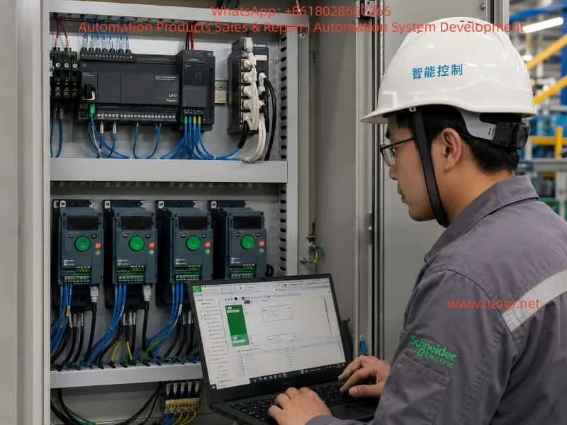
In small automation systems, tank control, pump stations, mixing equipment, conveyors and multi-motor applications, it is common to use one PLC to control several variable frequency drives. The control requirements usually include start, stop, speed reference, fault monitoring, running status feedback and centralized operation from an HMI. Compared with traditional terminal control, Modbus RTU control reduces hardwiring, allows the PLC to read more drive data, and makes it easier for the HMI to display frequency, current, status and fault information for each drive.
However, many field problems in these systems are not caused by a single wiring mistake or a missing ladder rung. The real problems often come from unclear system architecture, incorrect Modbus roles, duplicated slave addresses, wrong register addresses, misunderstanding of relay feedback, improper power supply conditions, and an incorrect commissioning sequence. This becomes even more obvious when different brands and series of drives are connected on the same Modbus RTU network, such as Schneider ATV310, Schneider ATV31P and Allen-Bradley PowerFlex 525. If all drives are treated as if they use the same control word, the same speed reference register and the same status word, the system will easily fail.
A typical system may consist of a Schneider M221 PLC as the main controller, an LU9GC3 as the Modbus RTU distribution module, several variable frequency drives as Modbus slaves, and a Schneider Harmony HMI as the operator interface. In this type of project, the key is not only how to draw the ladder logic. The complete engineering work must include communication architecture, Modbus address planning, drive parameter settings, PLC logic structure, relay feedback wiring, HMI design, power supply verification and step-by-step commissioning.
1. Correct System Architecture: PLC as Master, Drives as Slaves, HMI as Operator Interface
In a Modbus RTU system, there must be only one master on the same serial bus. The master sends read and write requests, and the slaves only respond to the master. In this application, the correct structure should be:
Schneider Harmony HMI
        ↓
Ethernet or HMI communication to PLC
        ↓
Schneider M221 PLC / TM221CE24R
        ↓
Modbus RTU Master
        ↓
Schneider LU9GC3 Modbus distribution module
        ↓
Multiple VFDs as Modbus RTU slaves
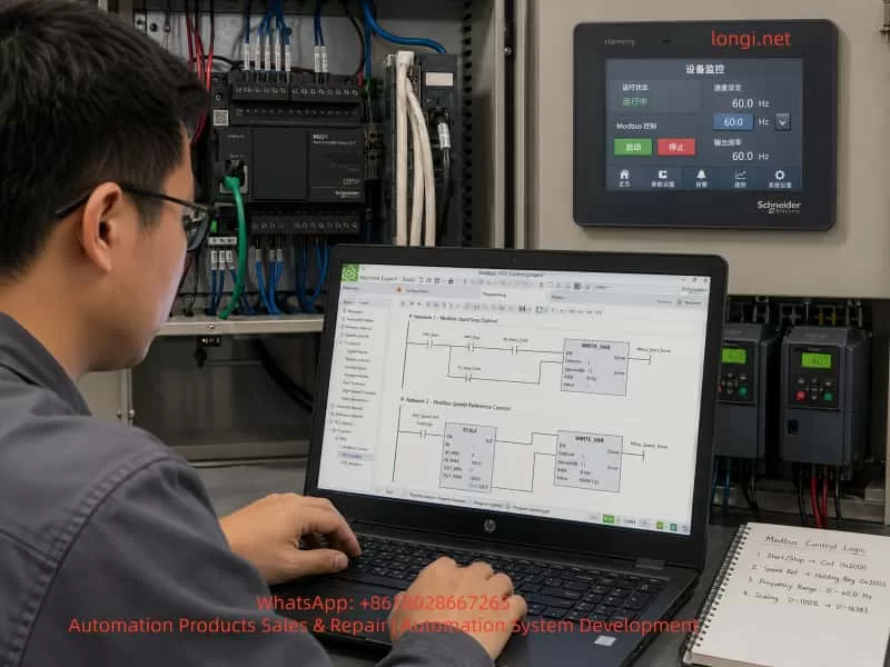
The HMI should not directly control all the drives on the Modbus RTU line. Its function is to send operator commands to the PLC, such as start, stop, reset and speed reference. The PLC then processes the logic and sends Modbus commands to the drives. The PLC also reads the drive status and sends this information back to the HMI for display.
A common misunderstanding in the field is confusing “HMI” with “HDMI.” HDMI is a video interface. HMI means Human Machine Interface, which is the industrial touchscreen used for operation and monitoring. A Schneider Harmony 7-inch touchscreen is an HMI, not an HDMI control device. It should communicate with the PLC, and the PLC should handle the actual drive control.
2. LU9GC3 Is Not an Ethernet Switch
The LU9GC3 module has several RJ45 ports, so it is often mistaken for a normal Ethernet switch. This is a serious misunderstanding.
The LU9GC3 is a Modbus serial distribution module, not a TCP/IP Ethernet switch. It is used to distribute one Modbus serial line to several devices such as VFDs or soft starters. It does not perform Ethernet switching, and it does not automatically convert Modbus TCP to Modbus RTU.
The correct use is:
PLC serial port / Modbus RTU master
        ↓
LU9GC3
        ↓
ATV310, ATV31P, PowerFlex 525 and other Modbus RTU slaves
The HMI should not be connected to the LU9GC3 as if it were an Ethernet network switch. If the HMI has an Ethernet port, it should normally connect to the PLC Ethernet port or to a real Ethernet switch in the PLC-HMI network. The LU9GC3 should only be used for the serial Modbus RTU connection between the PLC and the drives.
3. Each Drive Must Have a Unique Modbus Address
A Modbus RTU bus can have multiple slave devices, but each slave must have a unique address. If two drives have the same address, both may respond when the PLC sends a request to that address. This causes communication conflicts, invalid data, timeouts or unstable operation.
For a system with five drives, the address plan can be:
Device
Suggested Modbus Address
PowerFlex 525
1
ATV310 7.5 kW
2
ATV310 5.5 kW #1
3
ATV310 5.5 kW #2
4
ATV31P 5.5 kW
5
The exact order is not mandatory, but two rules must be followed:
Each address must be unique. The slave address in the PLC program must match the actual address set in the drive.
If all drives remain at the factory default address, for example address 1, communication may work when only one drive is connected. But once several drives are connected to the bus, the PLC will receive conflicting replies. This is one of the most common reasons why a single-drive Modbus test succeeds but a multi-drive network fails.
4. Communication Format Must Be the Same for All Devices
Modbus RTU communication requires not only correct slave addresses but also identical serial settings. The main settings are:
Baud rate: 9600 or 19200
Data bits: 8
Parity: Even or None
Stop bit: 1
Protocol: Modbus RTU
A practical starting point is:
19200 bps, 8E1
or:
9600 bps, 8E1
The most important point is consistency. The PLC, ATV310 drives, ATV31P drive and PowerFlex 525 must use the same baud rate, parity and stop bit. If one device has a different communication format, that device will not respond correctly to the PLC.
For initial commissioning, it is not recommended to use a very high baud rate. A Modbus RTU network with several VFDs is exposed to electrical noise, long cables, grounding problems and shielding issues. Lower or moderate baud rates are usually more stable during commissioning. After the system is working reliably, the communication cycle and baud rate can be optimized if necessary.
5. Modbus Control Principle for Schneider ATV310
To start and control an ATV310 through Modbus, two conditions must be met.
First, the drive communication parameters must be correct. Second, the command source and frequency reference source must be set to the communication channel.
If the drive is still configured for terminal start or keypad speed reference, the PLC may write control words and frequency references successfully, but the drive will not run. This often leads technicians to believe that the PLC program is wrong, when the real issue is the drive control channel setting.
The ATV310 normally requires configuration of the following items:
Modbus slave address
Baud rate
Communication format
Command source
Frequency reference source
Control profile
In the PLC program, at least two write operations are normally required:
Write command word: start, stop, reset
Write frequency reference: for example 10 Hz, 20 Hz, 50 Hz
At the same time, the PLC should read status information:
Running status
Fault status
Actual frequency
Output current
Communication status
For the first commissioning stage, the best approach is not to build the full automatic process immediately. A safer and clearer sequence is to test one ATV310 first:
1. PLC reads the ATV310 status register successfully.
2. PLC writes a low speed reference, such as 10 Hz.
3. PLC writes a start command.
4. ATV310 starts from the PLC command.
5. PLC writes a stop command.
6. ATV310 stops from the PLC command.
7. PLC identifies drive fault or communication error.
After one ATV310 works correctly, the same logic can be copied and adjusted for the other ATV310 drives.
6. PowerFlex 525 Cannot Use the Same Register Table as Schneider ATV310
In a mixed system, the Allen-Bradley PowerFlex 525 must be treated separately. It may support Modbus, but its parameter numbers, command source settings, Modbus register addresses, speed reference scaling and status word definitions are not the same as Schneider ATV310.
This is a critical point. All VFDs are not identical just because they all use Modbus. Different manufacturers implement Modbus control in different ways. Even when they all have a command word and a speed reference, the addresses, bit definitions, scaling and command values can be different.
For PowerFlex 525, the RS485 Modbus node address is typically set in:
C124 [RS485 Node Addr]
If the PowerFlex 525 is planned as slave address 1, then:
C124 = 1
Other important parameters include:
P046 [Start Source 1]: start command source
P047 [Speed Reference 1]: speed reference source
C123 [RS485 Data Rate]: RS485 communication speed
C127 [Comm Format]: communication format
C128 [Comm Write Mode]: communication write mode
If the drive must start and receive speed reference through Modbus, the start source and speed reference source must be set to the serial or DSI communication source. Otherwise, the PLC may communicate with the drive but still fail to start it.
In the PLC program, the PowerFlex 525 should have its own control block, for example:
VFD1_PowerFlex525
It should not share the same internal register mapping as the ATV310. The external interface can look the same for all drives, such as Start, Stop, Reset, Speed_Set, Run_Status, Fault_Status and Comm_Error. But the internal Modbus read/write addresses must match the specific drive model.
7. Recommended PLC Program Structure: Common Interface, Separate Drive Blocks
In a multi-drive system, the operator wants a consistent HMI interface, but each drive may require different Modbus registers. The best PLC structure is therefore:
Common HMI interface
Different internal Modbus blocks for each drive
For example, the HMI can provide the same commands for every VFD:
Start
Stop
Reset
Speed reference
Running status
Fault status
Communication status
Actual frequency
Actual current
But inside the PLC, each drive should have its own logic section or function block:
1. Generate internal run command from HMI request.
2. Check permissive conditions.
3. Generate the correct command word for that drive.
4. Write speed reference.
5. Read status word.
6. Decode running and fault states.
7. Detect communication error.
8. Send status back to the HMI.
This structure keeps the main program clear. The HMI remains consistent, while the brand-specific details are isolated inside each drive control block.
8. Ladder Logic Should Not Copy a Direct Motor Starter Diagram
A normal motor starter ladder diagram usually contains:
Start button → latch circuit → contactor output
Stop button → break output
Timer → start next motor
This logic is useful for learning ladder basics, but it cannot be directly used for Modbus drive control. A Modbus-controlled VFD does not start because a PLC output coil turns on. It starts because the PLC writes the correct command word to the correct Modbus register.
The correct logic should be:
Start button or HMI start command
        ↓
PLC internal run command
        ↓
Check safety and permissive conditions
        ↓
Write drive command word
        ↓
Write frequency reference
        ↓
Read drive status word
        ↓
Display running, stopped, fault or communication error on HMI
The PLC physical outputs Q0.0, Q0.1, etc. may not be used for drive start at all. The main control is through Modbus. Physical inputs and outputs are mainly used for emergency stop, interlock, relay feedback and backup hardwired protection.
A basic internal run latch can be designed with the following conditions:
Start condition:
HMI_START = 1
Emergency stop OK = 1
Drive R1 feedback OK = 1
Modbus communication OK = 1
Drive fault = 0
When all conditions are satisfied:
RUN_CMD = 1
Stop conditions include:
HMI_STOP = 1
Emergency stop active
R1 feedback abnormal
Communication fault
Drive fault
If any stop condition is present:
RUN_CMD = 0
Then the Modbus command is generated from RUN_CMD:
The frequency reference is written separately, for example:
HMI_SPEED_SET = 10.0 Hz
PLC converts it to the correct register value
PLC writes it to the drive speed reference register
9. R1 Relay Feedback Is Auxiliary Protection, Not a Replacement for Modbus Status
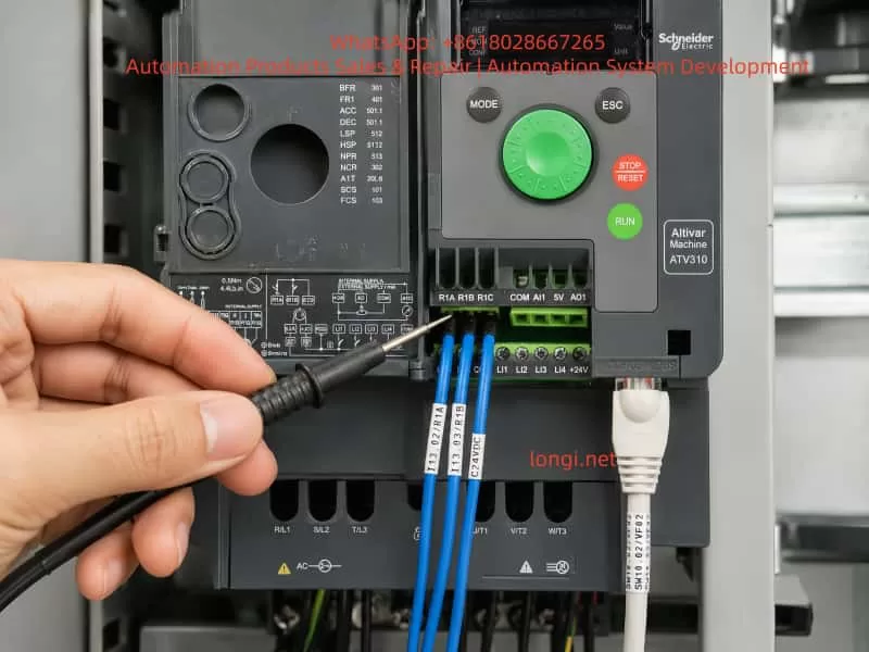
The ATV310 has relay terminals R1A, R1B and R1C. In most cases:
R1C = common
R1A = normally open contact
R1B = normally closed contact
R1A and R1B are not two separate fault signals. They are opposite contacts of the same relay. If R1C is connected to +24 V, R1A is connected to one PLC input, and R1B is connected to another PLC input, the two inputs will normally show opposite states.
For example:
Relay energized: R1A-R1C closed, R1B-R1C open
Relay de-energized: R1B-R1C closed, R1A-R1C open
In practical engineering, one contact per drive is normally enough for a fault or permissive feedback signal. A normally closed contact is often preferred for protection because a broken wire can also be detected as an abnormal condition.
A typical connection can be:
+24 V → R1C
R1B → PLC input
PLC input common → 0 V
However, the actual meaning of the input depends on how the drive relay function is configured. The R1 relay can be assigned to fault, run, ready, frequency reached or other functions. The PLC program must clearly define what the input means. It should not mix “running feedback,” “fault feedback” and “start permissive” without clear logic.
The best practice is to use both Modbus status and relay feedback:
Modbus status word: running, stopped, fault code, frequency, current
R1 relay: hardwired permissive or fault protection
If only R1 is used, the PLC cannot know the detailed fault. If only Modbus is used, a communication failure may remove an important hardwired protection path. Combining both gives a more robust system.
10. Each VFD Should Have Its Own Fault Feedback Input
For a five-drive system, each drive should ideally have a separate relay feedback input to the PLC:
If all R1 contacts are combined into one general fault input, the PLC will only know that one drive has a problem, but it will not know which one. This makes troubleshooting slower and less professional.
If PLC inputs are limited, a compromise can be made. Critical drives can have separate hardwired feedback, while less critical devices can rely on Modbus status. But in a new system design, saving a few input points should not be more important than clear fault diagnosis.
11. Modbus Wiring Must Consider Bus Topology, Shielding, Termination and Grounding
RS485 / Modbus RTU wiring is simple in principle, but it is sensitive to poor installation. VFDs are strong sources of electrical noise. PWM motor cables, braking resistors, contactor coils, grounding problems and power harmonics can all affect communication quality.
Important wiring rules include:
Use twisted shielded cable for RS485 communication.
Do not run communication cable parallel to motor power cables for long distances.
Keep the bus structure clear and avoid random star wiring.
Use termination resistors at the ends of the bus when required.
Handle shield grounding correctly to avoid ground loops.
Do not reverse D0 and D1.
Do not treat RJ45 Modbus ports as normal Ethernet ports.
Each slave address must be unique.
All serial settings must be the same.
Add one device at a time during commissioning.
Many Modbus failures are not caused by the PLC program. They are caused by wiring topology, shielding, grounding, termination or duplicated addresses. When five VFDs are connected to the same bus, it is much better to add and test one device at a time.
12. Commissioning Should Start with One Drive, Not the Entire System
A reliable commissioning sequence is essential. The recommended order is:
Confirm PLC model, HMI model, VFD models and communication interfaces.
Confirm the function and wiring of the LU9GC3.
Connect only one ATV310 first.
Set its Modbus address, baud rate, parity and stop bit.
Set its command source and speed reference source to Modbus.
Configure the M221 serial line as Modbus RTU master.
Read one status register from the ATV310.
Write a low frequency reference, such as 10 Hz.
Write the start command.
Confirm that the drive starts.
Write the stop command.
Confirm that the drive stops.
Read fault and running status.
Copy the logic to the other ATV310 drives.
Commission the ATV31P separately.
Commission the PowerFlex 525 separately.
Integrate the HMI operation screen and alarm screen.
Test emergency stop, communication loss, relay feedback and fault reset.
Finally run the motors under correct power supply conditions.
The worst approach is to connect all five drives, write all the logic, power everything up and then start troubleshooting. When many problems exist at the same time, it becomes difficult to know whether the fault is caused by addressing, parameters, wiring, registers, power supply or logic.
13. Do Not Run VFDs from an Improvised Single-Phase Capacitor Supply
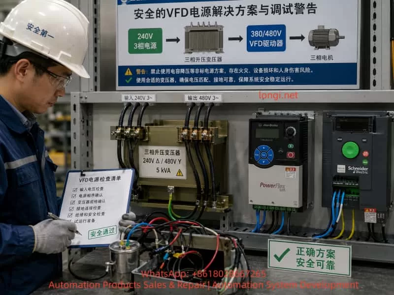
In some field situations, the available power supply may not match the VFD input voltage. For example, the site may only have 240 V three-phase power, while the drives or equipment require 380 V, 400 V or 480 V three-phase input. Sometimes a technician may try to create a temporary “480 V single-phase” supply and use a capacitor to simulate a missing phase.
This is not a proper power supply for VFD operation.
A VFD input rectifier requires a stable and balanced AC power source. A single-phase high-voltage supply with a capacitor does not become a real three-phase supply. It may cause:
Severe input voltage imbalance
DC bus ripple
Input phase loss fault
Undervoltage or overvoltage fault
Rectifier bridge overheating
Pre-charge circuit damage
Capacitor overheating or explosion
Ground fault or leakage trip
Permanent drive damage
If the site only has 240 V three-phase power and the drives require 380/400/480 V three-phase input, the correct solution is:
240 V three-phase supply
        ↓
Three-phase step-up transformer
        ↓
380/400/480 V three-phase supply
        ↓
VFD input
A properly sized three-phase transformer, correct grounding and correct protection devices are required. PLC, HMI and Modbus communication can be tested first without running the motor. High-voltage drive operation should only be tested when the power supply is correct and safe.
14. HMI Design Should Include Operation, Status and Alarms
In a multi-drive system, the HMI should not only have start and stop buttons. A practical HMI should include operation commands, real-time status and alarm information.
The naming style should be consistent. This makes it easier to copy logic, link HMI objects and troubleshoot the system later. The brand-specific differences should be handled inside the drive block, not scattered throughout the HMI and main program.
16. Run Command and Safety Permissives Must Be Separated
The PLC program should separate the operator request from the actual permission to run. An HMI start button only means the operator wants to start the drive. It does not mean the drive is allowed to start immediately.
Before the PLC sends a start command, it should check:
Emergency stop OK
Safety door OK
Drive not faulted
Communication OK
R1 feedback OK
Motor protection OK
Process conditions OK
Valid speed reference
No interlock conflict
The logic should be layered:
HMI_START → operator request
RUN_PERMISSION → permissive conditions
RUN_CMD → internal PLC run command
MODBUS_COMMAND → actual command written to the VFD
This prevents accidental operation and makes diagnostics easier. If the operator presses Start but the drive does not run, the HMI can show “start condition not satisfied” and then indicate whether the problem is R1 feedback, communication fault, emergency stop, drive fault or another interlock.
17. Stop Command Must Have Higher Priority Than Start
In any motor control system, stopping and fault handling must have higher priority than starting. The PLC logic should follow these rules:
Stop has priority over start.
Fault has priority over run.
Emergency stop has priority over normal stop.
Communication fault should inhibit start.
If HMI_START and HMI_STOP are active at the same time, the PLC should stop the drive. If RUN_CMD is active but R1 feedback becomes abnormal, the PLC should remove the run command. If Modbus communication is lost, the PLC should stop sending run commands and display a communication fault.
The VFD’s own communication-loss behavior should also be configured. Some drives can be set to coast stop, ramp stop, hold last command or trip on communication timeout. For most industrial systems, communication loss should cause a stop or a fault response, not continued operation with the last command.
18. Main Challenges in a Mixed-Brand VFD System
The difficulty in this type of project is not only one drive. It is the mixed-brand system. The main challenges include:
Schneider ATV310 and Allen-Bradley PowerFlex 525 use different Modbus register maps.
The command word bit definitions may be different.
The speed reference scaling may be different.
The status word decoding may be different.
The fault reset command may be different.
The communication parameter menus are different.
Some drives default to terminal control, while others may default to keypad control.
Communication timeout behavior must be configured.
The HMI should be unified, but the low-level Modbus control cannot be identical.
The field power supply may not be suitable for all drives.
Therefore, the project should not be reduced to “how to draw the ladder.” The complete design must include architecture, parameters, addresses, communication, power, safety and commissioning sequence.
19. Recommended Implementation Procedure
For similar projects, the following implementation procedure is recommended.
Step 1: Build a Device List
Record the following information for each device:
Brand
Model
Power rating
Input voltage
Communication interface
Modbus address
Communication format
Command source
Speed reference source
Step 2: Confirm Power Supply Conditions
Check:
Voltage level
Number of phases
Available capacity
Grounding
Circuit breaker
Leakage protection
Transformer capacity
Motor rated data
If the power supply is not suitable, fix the power supply first. Do not force the VFDs to run from an unsafe temporary source.
Step 3: Test One Drive Communication
Connect only one drive and confirm that the PLC can read and write data.
Step 4: Test One Drive Operation
Run at low frequency, preferably no load or light load, and confirm start and stop.
Step 5: Test Status Reading
Read running state, stopped state, fault state, current and frequency.
Step 6: Test R1 Relay Feedback
Create or simulate a status change and confirm that the PLC input changes correctly.
Step 7: Add Drives One by One
Add one drive to the Modbus bus at a time and test after each addition.
Step 8: Commission the HMI
Link HMI buttons, setpoints, status indicators and alarms.
Step 9: Test Safety Interlocks
Test emergency stop, communication interruption, drive fault, broken feedback wire and power recovery.
Step 10: Run with Load
Under correct three-phase power, gradually increase speed and monitor current, temperature and mechanical behavior.
20. Conclusion
Using an M221 PLC to control multiple VFDs through Modbus RTU is a practical and powerful industrial control solution. It reduces hardwiring, improves system integration, and allows the HMI to display drive status, fault information, current and frequency. But such a system cannot be understood as simply “the PLC sends one start command and the drive runs.” A reliable system must handle communication roles, unique slave addresses, serial settings, register differences, command word logic, relay feedback, HMI design, safety interlocks and correct power supply conditions.
In a mixed system using Schneider ATV310, Schneider ATV31P and Allen-Bradley PowerFlex 525, the most important rules are:
Use one clear architecture.
Assign unique slave addresses.
Keep communication settings consistent.
Use different Modbus register maps for different drives.
Build modular PLC logic.
Commission one drive at a time.
The HMI should be only the operator interface. The PLC should be the only Modbus RTU master. The drives should be Modbus slaves. The LU9GC3 should be treated as a Modbus serial distribution module, not as an Ethernet switch. The PowerFlex 525 Modbus address should be set through C124, and its start source, speed reference source and communication format must be configured separately. The ATV310 and ATV31P should be configured according to the Schneider drive communication table and control profile.
Power supply conditions must also be respected. If a drive requires 380 V, 400 V or 480 V three-phase input, but the site only has 240 V three-phase power, the correct solution is a properly sized three-phase step-up transformer. A single-phase high-voltage supply with a capacitor cannot replace a real three-phase supply and should not be used for normal VFD operation.
The safest commissioning strategy is to divide the project into small, verifiable steps. First test one drive, then expand to multiple drives. First read status, then write speed. First run at low speed, then test under load. First make communication stable, then complete the HMI and automatic logic. By following this method, a complex multi-drive Modbus RTU system can be transformed into a clear, maintainable and reliable industrial control project.
On CNC machines equipped with a FANUC 18M control system, the servo system is usually composed of a PSM power supply module, SVM servo amplifiers, spindle amplifier, motor feedback circuits, and the CNC-side serial servo interface. FANUC α series servo systems are generally reliable, but once a fault occurs in the control card, power card, IPM module, auxiliary power supply, or serial feedback chain, the alarm symptoms can overlap and mislead the repair process.
The case discussed here involves a horizontal machining center using a FANUC 18M CNC system. The machine is fitted with FANUC α series servo amplifiers. The Y-axis servo amplifier is A06B-6079-H106, and the control board is A20B-2001-093.
The reported symptoms include:
The Y-axis servo amplifier shows an 8-dot alarm on the seven-segment LED.
The CNC screen displays 414 SERVO ALARM: Axis Detect Error.
Another axis, such as B axis, also shows 351 SPC ALARM: Communication.
At first, the LED flickered, then the internal fuse blew, with a burnt smell.
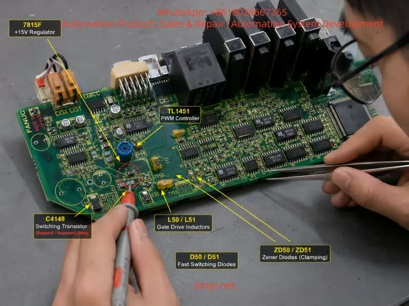
A transistor marked C4148 on the control board was found shorted.
After replacing C4148, the fuse did not blow immediately, but once the power card was connected, the amplifier again showed 8-dot, and after several minutes the fuse blew again.
On the B-axis control card, when only 24V was supplied with the power card removed, the seven-segment LED showed a “-” sign. But after installing the power card, the “-” appeared briefly and then disappeared.
On the CNC diagnostic monitor, one or more axes were not detectable.
These symptoms should not be treated as a simple parameter problem, encoder fault, or servo initialization issue. The combination of repeated fuse blowing, burnt smell, seven-segment 8-dot alarm, damaged transistor, and failure after installing the power card strongly indicates a real hardware fault inside the servo amplifier.
The most likely fault area is the auxiliary switching power supply, power card load, IPM/IGBT drive circuit, current detection circuit, or servo communication detection circuit.
2. Meaning of “L Axis” in FANUC α Servo Amplifiers
When diagnosing FANUC α series servo amplifier alarms, the terms L axis, M axis, and N axis often appear in alarm descriptions. These terms can easily be misunderstood.
They do not necessarily refer to the actual machine axes such as X, Y, Z, B, or C. Instead, they refer to the internal amplifier channels.
Generally:
Servo amplifier type
Internal channel names
Single-axis SVM1 amplifier
L axis
Two-axis SVM2 amplifier
L axis and M axis
Three-axis SVM3 amplifier
L axis, M axis, and N axis
Therefore, if a single-axis amplifier is used for the machine Y axis, then the internal L axis of that amplifier is the machine’s Y axis.
For example, if the electrical cabinet arrangement is:
First module: PSM power supply module;
Second module: Y-axis single-axis servo amplifier;
Third module: X/Z two-axis servo amplifier;
Fourth module: spindle amplifier;
Then an 8-dot alarm on the second amplifier means the L-channel fault of that particular Y-axis amplifier. It does not mean that the machine has a separate “L axis”.
For the X/Z two-axis amplifier, the internal L and M channels must be identified by checking the motor power cable, feedback cable, CNC parameter assignment, and amplifier channel wiring. It cannot be judged only from the physical cabinet position.
This distinction is important. Otherwise, repair technicians may misinterpret “L axis” as the left-side module, left-side machine axis, or a nonexistent axis, causing the diagnosis to go in the wrong direction.
3. Relationship Between 414 Alarm and 351 Alarm
The FANUC 18M alarm 414 SERVO ALARM: Axis Detect Error is a broad servo detection alarm. It does not point to only one specific component. It means the CNC has detected a serious servo-related abnormality for one axis.
Possible causes include:
Internal overcurrent in the servo amplifier;
IPM or IGBT module abnormality;
Current detection circuit fault;
DC link voltage detection fault;
Servo amplifier control power supply abnormality;
Amplifier initialization failure;
Serial communication failure between CNC and servo amplifier;
Encoder feedback communication fault;
Mismatch between CNC parameters and actual servo hardware;
Failure of an upstream servo module affecting downstream detection.
The 351 SPC ALARM is usually related to serial pulse coder communication. Common causes include encoder cable failure, encoder damage, servo feedback interface fault, or CNC-side feedback communication abnormality.
In many actual repair cases, 414 and 351 appear together. This does not always mean the encoder itself is defective. If the control power supply of a servo amplifier is unstable, or if the servo communication chain is interrupted, the CNC may fail to detect downstream axes correctly and then generate both 414 and 351 alarms.
In a FANUC α servo system, several servo amplifiers may be connected in a communication chain. If the Y-axis amplifier has unstable control power, faulty serial communication, or a failed internal power supply, the following X/Z or B-axis amplifier may also become undetectable on the CNC screen. Therefore, a Z-axis or B-axis detect error does not automatically mean that the Z or B servo amplifier is the original fault.
The correct approach is to first repair or isolate the amplifier with obvious hardware failure, especially if it shows 8-dot, blows fuses, has burnt smell, and has damaged components.
4. Core Interpretation of the Y-Axis 8-dot Alarm
In this case, the Y-axis servo amplifier shows an 8-dot alarm and repeatedly blows the fuse. In FANUC α series servo amplifiers, 8-dot is typically related to inverter, IPM, overcurrent detection, or power drive section abnormality.
Although the exact meaning can vary depending on the amplifier generation and hardware version, the actual symptom combination is more important than the alarm code alone.
The key facts are:
The LED initially flickered;
The fuse blew;
There was a burnt smell;
C4148 on the control board was shorted;
After replacing C4148, the amplifier still showed 8-dot when the power card was installed;
The fuse blew again after a few minutes;
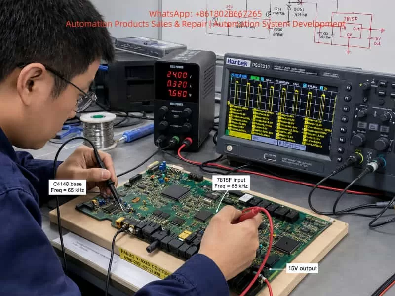
The waveform around C4148 showed high-frequency switching pulses;
The fault became worse only after the power card was connected.
These facts indicate that C4148 is unlikely to be the root cause. If C4148 were the only faulty component, replacing it should have restored stable operation. But the fault returned after installing the power card, which means the downstream load or related circuit is still abnormal.
A more reasonable conclusion is:
C4148 is being damaged by an abnormal load, short circuit, overvoltage spike, or switching power supply stress caused by the downstream power card or drive circuit.
The main suspect areas should therefore include:
Power card;
IPM / IGBT module;
Gate drive supply;
Current detection circuit;
Protection feedback circuit;
Secondary rectifier and filter circuit of the switching power supply;
Zener diodes and clamp diodes;
Optocoupler feedback circuit;
Connector interface between the control card and power card.
5. Analysis of the C4148, 7815F, and TL1451 Circuit
The hand-drawn circuit shows several important components: TL1451, 7815F, C4148, TR50, TR52, TR53, L50, L51, ZD50, ZD51, D50, D51, PM50, and PM51. Combined with the oscilloscope waveform, this area is not a simple static logic circuit. It is more likely a DC-DC auxiliary switching power supply or drive supply circuit on the servo control board.
5.1 Role of TL1451
TL1451 is a PWM controller. In a servo amplifier control board, it can be used to generate high-frequency PWM signals. These PWM signals drive transistors and magnetic components to produce multiple auxiliary supplies.
These auxiliary supplies may be used for:
IPM or IGBT gate drive;
Current detection isolation supply;
Protection and alarm detection;
Power card feedback;
Optocoupler isolation circuits;
Internal fault detection circuits.
The oscilloscope waveform showed that the base and emitter of C4148 had a pulse around 65 kHz. This matches the behavior of a PWM switching power supply. Therefore, TL1451 is at least oscillating, and the drive stage is working.
However, PWM waveform presence does not mean the power supply is healthy. If the secondary rectifier, filter capacitor, zener clamp, optocoupler feedback, or power card load is abnormal, TL1451 may continue to output PWM until the transistor, fuse, resistor, or another protection component fails.
5.2 Condition of 7815F
The measured waveform shows that the 7815F input is around 24V, and the output is around 15V. Both are relatively stable.
This indicates that the 24V-to-15V linear regulator stage is basically working at the moment of measurement.
If 7815F were the main faulty component, typical symptoms would include:
No 15V output;
Output voltage much lower than normal;
Large output ripple;
Voltage collapse after loading;
Severe heating of the regulator.
Since the 15V output is currently stable, 7815F should not be treated as the primary suspect. It is more likely providing supply voltage to TL1451 or nearby control circuits.
5.3 Meaning of the C4148 Waveform
The waveform on the base and emitter of C4148 shows a high-frequency pulse with about 30V peak-to-peak amplitude. If C4148 were used as a normal low-voltage transistor switch, such a waveform would be abnormal. A normal transistor base-emitter junction usually has about 0.6V to 0.8V forward voltage, and its reverse withstand voltage is limited.
Therefore, C4148 is probably located in a floating switching node, push-pull drive node, or transformer primary drive node.
Its failure may be caused by:
Excessive switching current due to downstream short circuit;
High leakage spike from a magnetic component;
Failed clamp diode or zener diode;
Cross-conduction in the transistor drive stage;
Abnormal PWM duty cycle;
Optocoupler feedback failure;
Power card auxiliary supply being pulled down;
IPM drive supply short circuit.
This also explains why replacing C4148 alone did not solve the fault.
6. Why the Fault Becomes Worse After Installing the Power Card
A key observation is that when the control card is powered alone, some voltages and waveforms can be established. But once the power card is installed, the Y-axis amplifier shows 8-dot and then blows the fuse. The B-axis has a similar pattern: the control card can display “-” with only 24V, but the display disappears after installing the power card.
This type of symptom usually means:
The power card or one of its connected loads is pulling down an auxiliary supply generated by the control board.
Possible causes include:
Short circuit in the IPM/IGBT drive circuit on the power card;
Shorted rectifier diode in the drive supply;
Leaky electrolytic or tantalum capacitor;
Shorted optocoupler or isolation amplifier;
Faulty current detection circuit;
Abnormal IPM alarm feedback line;
Leakage inside the IPM auxiliary terminal;
Contaminated, burnt, or bent connector pins between the control card and power card;
Low resistance on a 5V, 15V, 24V, or isolated drive supply line.
The fact that the fault becomes severe only after the power card is installed is very important. It means the repair should not stay only at the small components on the control board. If C4148, fuses, or resistors are replaced repeatedly without checking the power card load, the fault will return and may damage more parts.
7. Fuse Blowing Must Not Be Solved by Using a Thicker Fuse
In this case, the fuse was reportedly changed to “0.12 mm diameter × 2 strands”, and then it no longer blew immediately, but the amplifier still showed 8-dot.
This approach is risky.
The fuse is not only there to allow the machine to power up. Its function is to limit fault energy when a downstream circuit has a short. If a thicker fuse is installed without removing the fault, the result may be:
A small fault becomes a large burnt area;
The switching transistor fails again;
PCB copper tracks are damaged;
The IPM module receives secondary damage;
The CNC-side servo interface or communication circuit is damaged;
The short point becomes carbonized and harder to locate.
Therefore, when a fuse repeatedly blows, the correct solution is not to increase the fuse capacity. The correct procedure is to find the overcurrent branch using resistance measurement, diode-mode testing, current-limited supply injection, thermal inspection, and circuit isolation.
Only after the root cause has been removed should the original fuse specification be restored.
8. Recommended Diagnostic Procedure
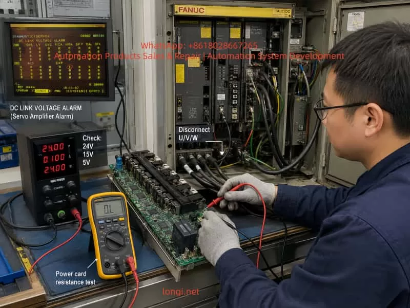
8.1 Disconnect Motor U/V/W First
The first step is to disconnect the Y-axis and B-axis motor power cables from the servo amplifiers, including U, V, and W.
This separates amplifier faults from motor, cable, or mechanical load faults.
The diagnostic logic is:
Test result
Interpretation
8-dot or fuse blowing still occurs with U/V/W disconnected
Internal amplifier fault is likely
Alarm disappears with U/V/W disconnected but returns when motor is connected
Motor, cable, or load-side fault is likely
Control power still collapses with the motor disconnected
Control card or power card auxiliary supply fault
Fault appears immediately when power card is installed
Power card or internal drive load short circuit
It is not recommended to continue energizing the amplifier before disconnecting the motor power cables.
8.2 Check Motor and Cable Insulation
The motor power cable insulation should be tested between:
U and PE;
V and PE;
W and PE;
U and V;
V and W;
W and U.
If the insulation to ground is low, or the three-phase resistance is unbalanced, the motor or cable may have an insulation breakdown.
Important warning:
Do not use a high-voltage megger on encoder cables, feedback cables, or communication cables. Doing so can damage the encoder and CNC feedback interface.
8.3 Check the IPM / IGBT Section
After full power-off and DC bus discharge, use a multimeter in diode mode or resistance mode to check:
P-N DC bus short circuit;
P-U, P-V, P-W;
N-U, N-V, N-W;
U/V/W phase-to-phase;
U/V/W to PE;
Braking circuit terminals, if applicable.
If one phase reads significantly different from the others, or if P/N to U/V/W shows near-short resistance, the IPM or IGBT module is highly suspect.
In that condition, further power-on testing may only cause more damage to the fuse, drive stage, or control board.
8.4 Check Control Board Low-Voltage Supplies
The following supplies should be measured carefully:
24V input;
15V regulated output;
5V logic supply;
TL1451 Vcc;
TL1451 reference voltage;
C4148 collector, base, and emitter;
ZD50 and ZD51 voltage;
Auxiliary supply lines at the power card connector.
Measurements should be taken under different conditions:
Power card removed;
Power card connected;
At the moment 8-dot appears;
Just before the fuse blows;
When the display disappears.
If the 15V or 5V collapses immediately after connecting the power card, the power card or its load is likely shorted. If the 24V current gradually increases and one component heats up, a thermal leakage fault may exist.
8.5 Measure Power Card Connector Resistance
With the machine powered off, discharged, and the power card removed, measure the resistance of the power card connector pins to 0V:
24V to 0V;
15V to 0V;
5V to 0V;
Drive auxiliary supply to its reference ground;
IPM alarm line to 0V;
Current feedback line to 0V;
Optocoupler supply line to 0V.
If one line reads only a few ohms or a few tens of ohms, follow that line to find the shorted component.
Common shorted parts include:
Tantalum capacitors;
Small electrolytic capacitors;
Zener diodes;
Rectifier diodes;
Gate driver ICs;
Optocouplers;
IPM internal auxiliary pins.
8.6 Use Current-Limited Power Injection
Repeatedly powering the amplifier from the machine supply is dangerous. A safer method is to inject voltage into the suspected branch using a current-limited bench power supply.
Suggested starting limits:
Supply branch
Injection voltage
Initial current limit
5V branch
3V to 5V
0.2A to 0.5A
15V branch
5V to 15V
0.1A to 0.3A
24V branch
12V to 24V
0.1A to 0.5A
After injecting voltage, check which component heats up. A thermal camera, infrared thermometer, alcohol evaporation method, or careful finger temperature check can be used.
If a zener diode, capacitor, driver IC, or optocoupler heats quickly, the shorted branch has likely been found.
8.7 Analyze the Failure Mode of C4148
After C4148 fails again, it should not simply be discarded. Remove it and test the failure mode:
Failure mode
Possible cause
Collector-emitter short
Excessive switching current, downstream short
Base-emitter short
Base drive overvoltage or reverse breakdown
Base-collector short
Switching spike or clamp failure
All three pins shorted
Severe overcurrent or overheating
Open circuit
Component burned open after transient breakdown
If the failure mode is the same each time, it can help identify the stress direction. For example, repeated collector-emitter shorting points to the main switching current path. Repeated base-emitter damage points to the base drive or clamp circuit.
9. Independent Analysis of the B-Axis Symptom
The B-axis control card can display “-” when only 24V is applied and the power card is removed. But after the power card is installed, the “-” appears briefly and disappears.
This is different from the Y-axis 8-dot symptom, but it still points toward a hardware power supply problem.
The fact that the control card can display “-” with only 24V means that at least part of the low-voltage logic can start. But when the power card is connected, the logic supply collapses or the control card shuts down.
Possible causes include:
Shorted power card;
Shorted connector between control card and power card;
Abnormal 5V, 15V, or 24V load on the power card;
Shorted drive supply or isolated supply;
IPM or gate driver IC internal short;
Feedback line abnormality causing protection shutdown.
Therefore, the B-axis fault should not be diagnosed as a parameter issue first. The correct direction is to check the power card, low-voltage loading, connector resistance, and auxiliary drive supply.
If a known-good board is used for cross-testing, all short-circuit checks must be completed first. Otherwise, a good control card or power card may be damaged by the same shorted load.
10. Chain Reaction of Axis Detect Errors
In FANUC 18M servo systems, the CNC communicates with the servo amplifiers through a defined serial chain. If an upstream servo module has abnormal control power or communication, downstream axes may also become undetectable.
Therefore, when the CNC displays Z-axis detect error or B-axis detect error, it does not always mean the Z-axis or B-axis amplifier is the original fault.
In this case, the Y-axis amplifier already has clear hardware fault evidence:
8-dot alarm;
Fuse blowing;
Burnt smell;
C4148 short circuit;
Fault returns when the power card is connected.
Therefore, the Y-axis amplifier should be treated as the first priority. After the Y-axis amplifier is repaired or isolated, the technician should check whether the X/Z or B-axis alarms remain. If the downstream axes become detectable again, the previous alarms were secondary communication effects. If the alarms remain, then the corresponding axis feedback cable, encoder, amplifier, and CNC parameter configuration should be checked separately.
11. Repair Strategy and Risk Control
For this type of FANUC α servo amplifier fault, the repair principle should be:
Isolate first, then power on. Measure shorts first, then waveforms. Use current-limited testing first, then full machine testing.
11.1 Practices to Avoid
The following actions are not recommended:
Repeatedly powering the amplifier directly on the machine;
Replacing the fuse with a thicker one;
Replacing only C4148 and continuing to test;
Judging the amplifier before disconnecting the motor;
Installing the power card before checking its resistance;
Using a high-voltage megger on encoder cables;
Swapping good and bad boards without short-circuit checks;
Treating fuse blowing and burnt smell as parameter faults.
11.2 Recommended Practices
The correct repair process should include:
Remove the faulty module for bench testing;
Restore the original fuse specification after repair;
Separate the control card, power card, and IPM for testing;
Compare resistance readings with a known-good axis card;
Measure TL1451-related supply and PWM signals;
Measure all power card interface supply lines to ground;
Find the downstream short before replacing C4148 again;
Perform no-load testing before connecting the motor;
Reconnect the motor only after 8-dot disappears;
Finally check whether CNC 414 and 351 alarms clear.
12. Practical Fault Location Map
For this kind of failure, the suspected areas can be divided into four levels.
Level 1: Control Board Auxiliary Supply
Components to check:
TL1451 PWM controller;
C4148 / TR53 switching transistor;
TR50, TR51, TR52 drive transistors;
7815F regulator;
ZD50, ZD51 zener diodes;
D50, D51 diodes;
L50, L51 magnetic components;
C57, C58, C59, C60, C61 capacitors;
PM50, PM51 optocouplers or feedback parts.
Possible faults:
PWM drive abnormality;
switching transistor overcurrent;
zener diode short;
filter capacitor leakage;
optocoupler feedback abnormality;
transformer or inductor winding fault.
Level 2: Power Card Load
Components or circuits to check:
5V/15V/24V load on the power card;
gate driver circuit;
IPM alarm feedback;
current detection circuit;
isolated power supply circuit;
connector pins;
power card electrolytic and tantalum capacitors.
Possible faults:
low-resistance short;
voltage collapse after connection;
thermal leakage;
optocoupler or driver IC short;
connector carbonization or contamination.
Level 3: IPM / IGBT Inverter Section
Check:
P-N;
P-U, P-V, P-W;
N-U, N-V, N-W;
U/V/W phase-to-phase;
U/V/W to PE;
braking circuit.
Possible faults:
internal IGBT short;
diode failure;
IPM alarm output abnormality;
phase output leakage;
drive supply short inside the module.
Level 4: External Motor and Cable
Check:
motor winding resistance;
insulation to ground;
power cable damage;
coolant/oil contamination in connectors;
mechanical load seizure;
brake release condition, if the axis has a brake.
Possible faults:
phase-to-ground leakage;
phase-to-phase short;
cable insulation breakdown;
connector contamination;
motor internal winding damage.
13. Final Conclusion
This fault is not a simple CNC parameter issue, nor is it a normal encoder communication problem. It is a hardware fault inside the FANUC α series servo amplifier that triggers a chain of servo alarms.
The Y-axis A06B-6079-H106 amplifier shows 8-dot, blows the fuse, produces a burnt smell, and damages C4148. The fault returns after the power card is installed. These symptoms strongly indicate that the real problem is located in the power card, IPM/IGBT drive circuit, auxiliary switching power supply, current detection circuit, or protection feedback circuit.
C4148 is only one damaged component in the fault path. It should not be treated as the root cause by itself.
The hand-drawn circuit and waveform analysis further show that C4148 belongs to a high-frequency auxiliary switching power supply controlled by TL1451. The 7815F regulator has approximately 24V input and 15V output, so the linear regulator itself is not the main suspect at this stage. The more important area is the downstream load of the TL1451 switching supply, including drive transistors, magnetic components, rectifier diodes, zener clamps, filter capacitors, optocoupler feedback, and the power card interface.
The B-axis symptom, where the control card shows “-” with only 24V but shuts down after installing the power card, also points to a power card or auxiliary supply load problem. It should be diagnosed as a hardware supply-loading fault before considering CNC parameters.
The CNC 414 and 351 alarms must be interpreted together with the actual amplifier condition. If one upstream amplifier has unstable control power or communication failure, downstream axes may also become undetectable. Therefore, the amplifier with the clearest hardware fault evidence should be repaired or isolated first.
The correct repair path is:
Disconnect motor U/V/W cables;
Check motor and cable insulation;
Measure IPM/IGBT bridge circuits;
Measure control board 24V, 15V, and 5V supplies;
Check TL1451 and C4148 switching supply behavior;
Measure power card connector resistance;
Use a current-limited bench supply to locate shorted branches;
Repair the downstream fault before replacing C4148 again;
Restore the original fuse specification;
Perform no-load testing first;
Reconnect the motor only after the 8-dot alarm disappears;
Finally verify that CNC 414 and 351 alarms are cleared.
Only this layered and isolated diagnostic method can prevent repeated fuse blowing, repeated C4148 failure, and further damage to the control board, power card, IPM module, or CNC servo interface. For aging FANUC α series servo amplifiers, this approach is safer and much closer to the real root cause than blindly replacing small components or randomly swapping modules.
In daily operation of a field-emission scanning electron microscope, the vacuum system is one of the most critical subsystems. It directly determines whether the microscope can image normally, whether the high voltage can be enabled safely, and whether the electron gun can be protected from contamination. For a field-emission SEM such as the ZEISS Sigma 300, the sample chamber, column chamber, electron gun chamber, backing pump, turbo molecular pump, vacuum gauges, pneumatic valves, and vacuum control electronics are all connected through a strict interlock logic. If any one of these conditions is not satisfied, the system will prevent EHT from being switched on and will keep the column chamber valve closed to protect the electron gun and electron optical column.
In this case, the ZEISS Sigma 300 was originally operating normally. The operator performed a standard venting procedure, opened the chamber, then closed the chamber and attempted to pump down again. After this operation, the chamber vacuum could not be restored normally. The software vacuum panel showed the status “Waiting Penning”, the EHT vacuum condition was not ready, the column chamber valve remained closed, and the microscope could not return to normal operating condition.
The field feedback also indicated that after power-on, the system automatically entered the pumping sequence. The chamber door could be pulled tight by negative pressure, and no obvious air leakage sound was heard. However, the chamber vacuum could not continue into the normal high-vacuum state. In some observations, the vacuum gauge reading was missing, invalid, or remained abnormal.
From a service diagnostic point of view, this type of fault should not be simplified as “the pump is bad” or “the vacuum gauge is bad.” The SEM vacuum system works in stages and has different vacuum zones. The fact that the chamber door can be sucked tight only proves that a rough vacuum is being formed. The software status Waiting Penning means that the system is waiting for valid confirmation from the Penning high-vacuum gauge or its related measurement circuit. If the system also shows Gun Vacuum = 1000 mbar, EHT Vac Ready = No, and Column Chamber Valve = Closed, it is necessary to distinguish whether the actual vacuum has not reached the required condition, or whether the vacuum measurement circuit, valve actuation, or control logic has failed to confirm the vacuum state.
2. Basic Structure of the ZEISS Sigma 300 Vacuum System
To understand this fault, it is necessary to understand the general structure of the SEM vacuum system. Different configurations of the ZEISS Sigma 300 may vary in detail, but the main vacuum architecture usually includes the following sections.
2.1 Sample Chamber Vacuum Area
The sample chamber is the vacuum area most frequently operated by users. During normal sample exchange, the system vents the chamber to atmospheric pressure through the vent valve. After the chamber door is closed, the system pumps the chamber down again through the pump sequence. The chamber door seal, door locking mechanism, sample stage height, sample holder, detector ports, EDS/EBSD/BSE accessory interfaces, and chamber flanges can all affect whether the sample chamber can establish vacuum normally.
Typical sample chamber faults include slow pump-down, failure to pump down, pressure remaining at a high level, chamber door not being sucked tight, or repeated vacuum timeout. Conductive adhesive, sample powder, metal particles, fiber, glove fragments, or contamination on the O-ring and sealing surface can prevent the chamber from reaching the required vacuum level. A damaged, displaced, hardened, or locally deformed O-ring can also cause the same problem.
2.2 Backing Pump and Rough Pumping Path
A ZEISS Sigma 300 may use an Edwards nXDS dry scroll pump as the backing pump. This pump is responsible for rough pumping the sample chamber and providing backing support for the turbo molecular pump. However, a running backing pump does not automatically mean that the entire vacuum system is healthy. It is only the first stage of the vacuum chain.
If the backing pump is completely non-operational, the chamber usually cannot form noticeable negative pressure. The chamber door will not be pulled tight, and the system vacuum will remain close to atmospheric pressure. If the backing pump runs but has poor pumping speed, the pressure may decrease slowly and fail to reach the condition required for high-vacuum transition. If the backing pump itself is normal but the pumping valve does not open, the vent valve does not close, or the pipeline has a leak, the chamber will still fail to enter the next vacuum stage.
2.3 Turbo Molecular Pump and High-Vacuum Stage
After rough pumping reaches a certain pressure, the system relies on the turbo molecular pump to continue pumping the chamber into the high-vacuum range. The turbo molecular pump must start, accelerate, reach operational speed, and enter a Ready or Normal state. The high-vacuum valve and related valves must also actuate correctly before the system can proceed to high-vacuum confirmation.
If the turbo pump does not start, if the controller reports an alarm, if the rotational speed is not reached, if the backing pressure is not acceptable, or if the high-vacuum valve does not open, the chamber may stay at several Pa or tens of Pa and the software may continue to display Waiting Penning, Vacuum not ready, or a similar interlock status.
2.4 Pirani Gauge and Penning Gauge
Different types of vacuum gauges are used to cover different pressure ranges. The rough vacuum range is commonly monitored by a Pirani gauge, while the high-vacuum range is commonly monitored by a Penning gauge or cold cathode gauge.
The Pirani gauge is used in the higher pressure range and is typically responsible for determining whether the sample chamber has moved from atmosphere into rough vacuum. The Penning cold cathode gauge is used in the high-vacuum range and usually works reliably only when the pressure is low enough. If the system displays Waiting Penning, it means the vacuum control sequence is waiting for the Penning gauge to provide a valid high-vacuum condition, or waiting for it to start, ignite, stabilize, and satisfy the interlock threshold.
A Penning gauge fault does not always generate an obvious error message. In some cases, the software only remains at Waiting Penning, while the server or message log does not show a red alarm. This can happen because the control system is simply waiting for a valid confirmation signal rather than classifying the condition as a hard error.
2.5 Vacuum Valves and Pneumatic System
Many SEM vacuum valves are pneumatically driven, including vent valves, pumping valves, high-vacuum valves, and column isolation valves. Insufficient compressed air pressure, detached air tubing, a defective solenoid valve, a stuck valve body, or missing valve feedback can all cause the vacuum sequence to stop at a certain stage.
For instruments that require the chiller and compressed air system to stabilize before power-on, the cooling water, water pressure, compressed air pressure, dry air supply, and external interlock conditions must all be confirmed. Otherwise, even if the pumps themselves are functional, the valves may not actuate correctly.
3. Initial Judgment Based on the Failure Sequence
The most important detail in this case is that the instrument was working before the chamber was vented and opened. The failure appeared when the chamber was closed again and the operator attempted to pump down. This background strongly suggests that the problem may be related to the open-chamber and re-pump sequence.
When a vacuum fault appears immediately after opening and closing the chamber, the first suspects are usually chamber door sealing, sample stage position, sample holder interference, O-ring contamination, vent valve return, or rough pumping path problems. These are the components most likely to change after user operation.
However, later observations showed that the sample chamber door was sucked tight immediately after pumping started, and there was no obvious air leakage sound. The software showed System Vacuum = approximately 8.4e-02 mbar to 8.6e-02 mbar, equivalent to about 8.4–8.6 Pa. This means the chamber was not at atmospheric pressure and rough pumping was not completely ineffective. The backing pump and rough pumping path were at least partly functional. A major leak at the chamber door became less likely.
At this point, the diagnostic focus should shift from “whether the chamber can form negative pressure” to “why the system cannot complete high-vacuum confirmation after rough pumping.” The software status Waiting Penning indicates that the system has reached the stage where it expects confirmation from the Penning high-vacuum gauge, but the Penning gauge or its related vacuum measurement circuit is not providing a valid state.
Therefore, the fault range should be narrowed to the following possibilities:
Penning / cold cathode high-vacuum gauge failure;
Penning gauge cable, connector, supply, or high-voltage excitation failure;
Gauge interface board or vacuum control board unable to read the Penning signal;
Turbo molecular pump not started, not accelerated, or not Ready;
High-vacuum valve not open or valve feedback not confirmed;
Vacuum measurement power supply, communication, or common measurement circuit fault;
Abnormal Gun Vacuum reading suggesting a wider measurement-channel issue.
4. Meaning of System Vacuum Around 8 Pa
A System Vacuum reading of around 8 Pa is an important diagnostic dividing point. Atmospheric pressure is about 101325 Pa, so 8 Pa is already far below atmosphere. This value can exclude some simple failures, but it does not prove that the high-vacuum system is normal.
4.1 Complete Rough Pumping Failure Becomes Less Likely
If the backing pump were completely inactive, or if the chamber door were not sealing at all, the System Vacuum would usually not decrease to around 8 Pa. The chamber door would also not be sucked tight quickly. Therefore, with the chamber already around 8 Pa, it is not correct to simply describe the problem as “the pump is not pumping” or “the chamber is still at atmosphere.”
4.2 Minor Leakage Still Cannot Be Fully Excluded
Although the door is sucked tight, a minor leak cannot be completely excluded. A small leak may still allow the chamber to reach several Pa, but prevent the system from reaching the lower pressure range required for high vacuum. Common leak sources include a contaminated O-ring, detector flange, chamber accessory port, vent valve leakage, or contaminated valve seal. However, if the software clearly remains at Waiting Penning and the high-vacuum gauge has no valid reading, the measurement and high-vacuum confirmation chain becomes the higher-priority suspect.
4.3 The System Is Likely Stuck at Rough-to-High-Vacuum Transition
A pressure of around 8 Pa is still within the rough-vacuum region. At this stage, the system may be preparing to start or confirm the turbo pump, high-vacuum valve, and Penning gauge. If the pressure cannot decrease further, it is necessary to determine whether the turbo pump has really accelerated, whether the high-vacuum valve has opened, and whether the Penning gauge has entered a valid operating condition.
5. Technical Meaning of “Waiting Penning”
Waiting Penning is not the same as a direct conclusion that “the Penning gauge is bad.” It is a process status. It indicates that the system is waiting for the Penning high-vacuum gauge or cold cathode gauge to satisfy a required condition. This condition may include gauge enable, high-voltage excitation, ignition, valid pressure range, stable reading, control-board signal recognition, and software interlock confirmation.
5.1 Penning Gauge Body Failure
After long operation, a Penning gauge may suffer from contamination, internal deposition, ignition difficulty, unstable discharge, reading drift, or no reading at all. Common contamination sources in SEM chambers include conductive adhesive, volatile organic samples, powder, oil vapor, water vapor, and solvent residue. These contaminants can reduce the reliability of the gauge and prevent stable discharge, so no valid high-vacuum reading is produced.
5.2 Gauge Cable or Connector Failure
A loose gauge cable, oxidized connector, damaged shielding, pulled cable, or poor contact can cause the software to lose the Penning signal. Such faults may not always produce a clear alarm. They may only appear as Waiting Penning or no gauge reading.
5.3 High-Voltage Excitation or Gauge Supply Failure
A Penning cold cathode gauge requires high-voltage excitation to operate. If the high-voltage excitation module, gauge supply, or interface output is abnormal, the gauge body may be good but still unable to produce a valid measurement signal.
5.4 Vacuum Control Board or Measurement Channel Failure
If the vacuum control board input channel is damaged, or the gauge interface module is faulty, the software may not receive the actual reading. If multiple vacuum readings are abnormal at the same time, for example if Gun Vacuum = 1000 mbar, the diagnosis should expand to the common vacuum measurement power supply, communication chain, control board, or data acquisition channel, rather than focusing only on one gauge.
6. Risk Significance of Gun Vacuum Showing 1000 mbar
In one observation, Gun Vacuum = 1000.00 mbar was displayed. This value is close to atmospheric pressure and is highly abnormal for a field-emission gun. A field-emission electron gun must be maintained at extremely high vacuum, usually far lower than the sample chamber pressure. If the gun chamber were truly at atmospheric pressure, it would be a serious fault. The EHT must not be switched on, and emission or imaging must not be attempted.
However, because an earlier observation had shown a normal high-vacuum gun value, such as 1.33e-07 Pa, the later value of 1000 mbar may also be a software default value, an unloaded reading during startup, a communication failure, a lost gun vacuum gauge signal, or an abnormal vacuum measurement system display. Regardless of the cause, as long as Gun Vacuum remains at 1000 mbar, all high-voltage operation must be prohibited.
This symptom also indicates that diagnosis should not focus only on the chamber Penning gauge. The entire vacuum measurement system needs attention. If the chamber Penning gauge has no valid reading and the gun vacuum reading is also abnormal, there may be a fault in common power supply, vacuum control electronics, communication, or multiple gauge signal channels.
7. Diagnostic Procedure and On-Site Inspection Method
7.1 Do Not Enable EHT or Force the Column Chamber Valve
When EHT Vac Ready = No, Column Chamber Valve = Closed, and the vacuum status is abnormal, the EHT must not be switched on. The column chamber valve must not be forced open through service mode. The closed column valve protects the electron gun and high-vacuum column. Forcing it open may contaminate the electron optical system.
7.2 Observe the Complete Vacuum Page
The complete software Vacuum page should be observed, not only a cropped screenshot. The following parameters should be recorded:
System Vacuum;
Gun Vacuum;
Vac Status;
Column Chamber Valve;
EHT Vac Ready;
Column Pumping;
Pump / Vent button status;
Bottom status indicators such as Vac, Gun, and EHT;
Any warning or message.
It is especially important to distinguish whether the System Vacuum is completely blank, fixed at atmosphere, decreasing to a certain value and stopping, or still slowly decreasing. These patterns correspond to different fault directions.
7.3 Record the Full Pump-Down Sequence
After clicking Pump or after automatic pumping at startup, a continuous video of at least 10–20 minutes should be recorded. The change of System Vacuum should be observed. If the pressure drops quickly from atmosphere to around 8 Pa and then remains there, the rough pumping is effective but the high-vacuum stage is not continuing. If the pressure does not change at all, the chamber seal, vent valve, pumping valve, and rough vacuum gauge should be checked again.
7.4 Check the Chamber Door and O-Ring
Although a major chamber leak is now less likely, the fault occurred after chamber opening, so the door seal should still be checked. The inspection should include:
Whether the O-ring is displaced;
Whether the O-ring has dents, cracks, hardening, or deformation;
Whether the sealing surface has conductive adhesive, dust, metal particles, or fibers;
Whether the sample stage is too high;
Whether the sample holder interferes with the door;
Whether a sample has dropped inside the chamber;
Whether detector ports or accessory flanges are loose.
An empty-chamber pump-down test is recommended to rule out sample or holder interference.
7.5 Check the Edwards Backing Pump
The backing pump should be checked for operating sound, indicator lamps, alarm status, pumping-load change, pipe connection, and exhaust condition. A running pump does not necessarily mean it has sufficient pumping speed or that the valve path is open. If the pump sounds unloaded all the time, the chamber may not be connected to the pump path. If the pump sounds heavily loaded but the pressure does not fall, there may be a large leak or a vent valve not fully closed.
7.6 Check the Turbo Pump and Controller
When System Vacuum has reached around 8 Pa, the turbo pump status becomes especially important. The following should be checked:
Whether the turbo pump starts;
Whether acceleration sound can be heard;
Whether the controller displays Ready, Normal, Acceleration, or Alarm;
Whether Fail, Error, or Overtemperature is present;
Whether backing pressure satisfies the turbo start condition;
Whether turbo pump cables and control lines are normal;
Whether the software shows any Turbo / TMP status.
If the turbo pump is not accelerating, even a good Penning gauge may not enter a valid high-vacuum measurement range.
7.7 Check the Penning / Cold Cathode Gauge
The Penning gauge body should be located, and its model, installation position, cable, and connector condition should be recorded. The key inspection points are:
Whether the connector is loose;
Whether the cable has been pulled or damaged;
Whether the connector is oxidized;
Whether the gauge is contaminated;
Whether the gauge is connected to the correct vacuum region;
Whether a replacement gauge is available for cross-testing;
Whether gauge supply or high-voltage excitation is normal.
If conditions allow, replacing the gauge with the same model or cross-checking the channel can help determine whether the fault is in the gauge body, the cable, or the control electronics. This must be done carefully by personnel familiar with the system, because incorrect handling of gauge wiring or high-voltage connectors can cause additional damage.
7.8 Check Compressed Air and Valve Group
Many SEM vacuum valves are pneumatic, so compressed air must be checked. The inspection should include:
Air compressor output pressure;
Instrument air pressure gauge;
Whether the air supply is dry;
Whether any air tube is loose;
Whether valve manifold indicators are normal;
Whether valve actuation sound is heard during Pump / Vent;
Whether the vent valve fully closes;
Whether the high-vacuum valve actuates;
Whether valve feedback is received by the control system.
If the high-vacuum valve does not open, the chamber may remain in the rough-vacuum stage and the software may continue waiting for Penning confirmation.
7.9 Check Logs and Status Records
Even if the server shows no obvious error, the Message Log, Event Log, and Vacuum Log should be reviewed. The following keywords are especially important:
Penning;
Cold Cathode;
Gauge;
Pirani;
TMP;
Turbo;
Valve;
Vacuum timeout;
Gun vacuum;
EHT;
Interlock.
No error message does not mean no fault. Many interlock conditions are shown only as a waiting state and may not be classified as an error.
8. Fault Priority Analysis
Based on the observed symptoms, the likely fault priority can be ranked as follows.
8.1 Penning Gauge or Its Measurement Circuit
This is the most direct suspect. The software explicitly displays Waiting Penning, and the high-vacuum gauge remains without valid reading. If the turbo pump and high-vacuum valve are confirmed normal, then the Penning gauge body, cable, supply, interface board, or vacuum control board channel becomes the primary target.
8.2 Turbo Pump Not Ready
If the turbo pump has not reached operating condition, the chamber cannot enter the high-vacuum range, and the Penning gauge may not produce a valid reading. This must be confirmed by controller status and software status, not just by listening for pump noise.
8.3 High-Vacuum Valve or Pneumatic Valve Not Actuated
If the valve does not open or the feedback signal is missing, the system may wait for Penning in the control sequence while the actual high-vacuum path is not established. Insufficient compressed air, defective solenoid valves, stuck valve bodies, and failed valve feedback can all cause this condition.
8.4 Vacuum Measurement Control Module Fault
The abnormal Gun Vacuum = 1000 mbar is a signal that the fault may be wider than a single chamber gauge. If multiple readings are abnormal, the vacuum measurement module, control board, communication line, power supply, and interface electronics must be inspected. Replacing only the Penning gauge may not solve the problem.
8.5 Minor Leak or Contamination Preventing High Vacuum
Although the chamber can rough-pump to around 8 Pa, a small leak may still prevent high vacuum. If the turbo pump and Penning gauge are functional but the pressure cannot decrease further, the O-ring, flanges, detector interfaces, vent valve, and chamber leak paths should be inspected.
9. Repair Recommendations
9.1 Do Not Replace the Gauge Blindly
Although the Penning gauge is a highly suspicious component, it should not be replaced blindly before confirming the turbo pump, valve group, compressed air, and measurement circuit. Blind replacement may increase service cost and may not address the actual fault.
9.2 Perform On-Site Diagnosis First
A reasonable service process should begin with on-site diagnosis. The following items should be confirmed:
Sample chamber sealing;
Backing pump performance;
Rough vacuum reading;
Turbo pump status;
Compressed air pressure;
Valve actuation;
Penning gauge and cable;
Gun Vacuum reading;
Vacuum control board and log status.
If the fault is only a loose connector, light gauge contamination, valve state problem, sealing-surface contamination, or software state issue, cleaning, reconnecting, resetting, or state recovery may restore the system. If the gauge is damaged, the control board channel is defective, the turbo pump fails, or the valve group is damaged, a separate repair quotation and parts plan will be required.
9.3 Protect the Electron Gun During Service
The field-emission gun is highly sensitive to vacuum contamination. During diagnosis and repair, the following rules must be followed:
Do not switch on EHT;
Do not force the Column Chamber Valve open;
Do not repeatedly Pump and Vent unnecessarily;
Do not disassemble electron gun high-vacuum components;
Do not attempt emission while Gun Vacuum is abnormal;
Do not modify vacuum interlock parameters randomly in service mode;
Do not force the vacuum sequence when the chiller, water, or compressed air conditions are abnormal.
The software keeping the valve closed and EHT disabled is normally a protection mechanism. These protections should not be bypassed.
10. Typical Diagnostic Conclusion
For a ZEISS Sigma 300 with chamber vacuum abnormality, if the sample chamber door is sucked tight, the System Vacuum can fall to around 8 Pa, the software remains at Waiting Penning, the server shows no obvious error, and the high-vacuum gauge has no valid reading, the following stage conclusion can be made:
A major chamber door leak is less likely;
The backing rough-pumping system is not completely failed;
The fault is mainly concentrated in the high-vacuum confirmation chain;
The Penning / cold cathode gauge and its measurement circuit are the first suspects;
Turbo pump Ready status, high-vacuum valve actuation, and compressed air pressure must be checked at the same time;
If Gun Vacuum remains at 1000 mbar, the diagnosis must expand to the vacuum measurement control module, communication, or supply circuit;
Before EHT Vac Ready becomes valid, EHT must not be enabled and the column valve must not be forced open.
11. Conclusion
Vacuum faults in a scanning electron microscope cannot be diagnosed from one pressure value alone. They also should not be solved by replacing one component simply because a process status mentions a gauge. The ZEISS Sigma 300 vacuum system is built from the backing pump, turbo pump, Pirani gauge, Penning gauge, valve group, compressed air system, control electronics, and software interlocks. The chamber door being sucked tight means rough vacuum exists, but it does not mean high vacuum has been achieved. Waiting Penning points to the high-vacuum confirmation chain, but it does not prove that the Penning gauge body itself is definitely defective. An abnormal Gun Vacuum value further suggests a possible deeper issue in the vacuum measurement system.
The correct diagnostic method is to follow the vacuum establishment sequence step by step. First confirm chamber sealing and rough pumping capability. Then confirm the turbo pump and valve actuation. Next inspect the Penning gauge, cable, supply, interface board, and vacuum control board. Finally, use the logs and interlock status to determine whether a common measurement-circuit problem exists.
Only by distinguishing between “the actual vacuum has not reached the required condition” and “the vacuum may be present but the system cannot read or confirm it” can misdiagnosis and unnecessary replacement of expensive components be avoided.
For this type of fault, the key service focus should be on the Penning high-vacuum gauge and its measurement circuit, turbo pump Ready status, high-vacuum valve actuation, and the vacuum control module. Until the fault is clearly identified, EHT should remain off, the column chamber valve should remain closed, and any operation that may contaminate the electron gun or expand the fault should be avoided.
1. Background: A TEM Filament Is Not an Ordinary “Light Bulb”
In the JEOL JEM-1400 transmission electron microscope (TEM), the so-called “bulb” is actually the electron gun filament, which serves as the electron emission source. In tungsten-filament TEM systems, the filament does not provide illumination in the traditional optical sense. Instead, under high vacuum and high-voltage conditions, it emits electrons through thermionic emission. The emitted electron beam passes through the Wehnelt electrode, anode, condenser lens system, objective lens system, specimen region, and imaging system before finally forming an image on the fluorescent screen or digital camera.
Because of this, filament replacement is not merely a simple consumable replacement procedure. It directly involves the electron gun structure, vacuum system, high-voltage stability, beam current stability, gun alignment, and imaging calibration. A filament that can emit electrons does not necessarily mean the microscope has returned to optimal imaging performance. Many JEM-1400 systems exhibit the condition commonly described as “the microscope still works, but the image quality is poor” after filament replacement.
Typical symptoms include:
Reduced image brightness
Gray or low-contrast images
Difficulty focusing
Off-center beam spot
Uneven illumination
Unstable beam current
Poor high-magnification resolution
Increased camera noise
Beam drift or fluctuation
These issues cannot simply be attributed to “a bad filament” or “the wrong filament model.” Proper diagnosis requires systematic analysis of:
Filament compatibility
Installation orientation
Electron gun contamination
Vacuum condition
HT (high tension) voltage stability
Beam current stability
Filament saturation
Gun alignment after replacement
Beam alignment
Specimen condition
Camera and imaging settings
2. Basic Equipment and Filament Verification
For the JEOL JEM-1400, the instrument label typically identifies the system as JEM-1400 Electron Microscope along with its serial information. Systems equipped with HC (High Contrast) pole pieces are particularly sensitive to beam alignment, specimen height, beam stability, and sample thickness.
Replacement tungsten filaments are commonly labeled as:
FILAMENT / K-TYPE MA113008
Physically, these filaments generally consist of:
A circular metal mounting base
Ceramic insulation
Two electrical pins
A central tungsten emission wire
Installation is not simply a matter of inserting the filament assembly. The following factors significantly affect beam quality:
Filament center height
Pin contact quality
Tungsten wire position
Mounting orientation
Concentricity with the Wehnelt aperture
Even if the old filament was discarded and no reference photos exist, reliable diagnosis is still possible. Comparing the old and new filaments is only a secondary aid. The more important checks are:
Whether the filament model matches the electron gun configuration
Whether the replacement filament packaging corresponds to the proper JEM-1400 filament type
Whether the new filament is physically intact
Whether the tungsten wire is centered
Whether the pins are straight and undamaged
Whether stable beam current can be achieved after installation
Whether a controllable beam spot appears on the fluorescent screen
If these conditions are verified step by step, troubleshooting can continue even without the original filament.
3. Safety Conditions Before and After Filament Replacement
TEM filament replacement must follow strict high-voltage and vacuum safety procedures. The electron gun area of the JEM-1400 involves:
High voltage
High vacuum
Precision alignment structures
Clean internal surfaces
Improper handling may result in:
High-voltage discharge
Electron gun contamination
Reduced filament lifetime
Vacuum instability
Damage to the HT system
Before replacement, ensure:
HT is OFF
Filament power is OFF
The electron gun is fully cooled
The gun chamber has been vented properly
Only the filament assembly is accessed
No unrelated high-voltage covers are removed
Clean gloves and proper tools are used
Never touch:
Tungsten wire
Ceramic surfaces
Wehnelt aperture
Contact surfaces
Each disassembly step should be documented with photos, especially:
Mounting orientation
Insertion depth
Locking screw positions
After replacement, HT should not be enabled immediately. The gun chamber and associated vacuum regions must first recover to proper vacuum levels. Gun, Column, Specimen Chamber, and Detector Chamber should all reach READY status before HT and Filament are turned on.
Enabling HT under poor vacuum conditions may cause:
Gun discharge
Wehnelt contamination
Anode contamination
Instability of emission
4. Vacuum Status Is the First Requirement Before Judging Filament Performance
The JEM-1400 vacuum interface typically displays statuses for:
Gun
Column
Specimen Chamber
Detector Chamber
RT1
Penning Gauge
Before evaluating filament performance, vacuum conditions must first be confirmed.
Typical normal status indicators include:
Gun: Evac Ready
Column: Evac Ready
Specimen Chamber: Evac Ready
Detector Chamber: Evac Ready
RT1: Evac Ready
Penning Gauge: Vac Ready
If any section shows NOT READY, especially the Specimen Chamber, image quality evaluation becomes unreliable.
Common causes include:
Specimen holder not fully inserted
Chamber leakage
Vacuum valve issues
Incomplete evacuation
Damaged seals
Improper loading procedures
Under these conditions, HT may fail to activate properly, or image quality may degrade regardless of filament condition.
A common mistake is assuming: “The image quality became poor after filament replacement, therefore the filament is defective.”
However, if the vacuum condition itself is unstable, filament evaluation becomes meaningless.
5. Relationship Between HT, Filament, and Beam Current
The JEM-1400 requires HT voltage to generate the electron beam. Typical operating voltages include:
80 kV
100 kV
120 kV
Typical software status indications include:
HT ON
Current HT: 100.00 kV
Filament ON
Beam ON
Beam Current: tens of microamps
If HT remains OFF or Current HT remains at 0 kV, proper electron imaging cannot occur even if the filament is heated.
If the system displays:
HT ON
Current HT: 100.00 kV
Filament ON
Beam Current around 57–58 μA
Visible fluorescent beam spot
then the filament is clearly emitting electrons.
This does not automatically mean imaging performance is optimal. Beam current alone only confirms electron emission. Additional evaluation is required for:
Beam stability
Beam centering
Brightness
Beam symmetry
Saturation condition
Gun alignment
If Beam Current is approximately 57 μA and the fluorescent spot responds smoothly to Brightness adjustment, the filament should not immediately be considered defective.
In such cases, poor beam alignment after replacement is a far more likely cause.
6. How to Evaluate Beam Condition Without a Specimen
Although final imaging quality must ultimately be judged using a specimen, important preliminary evaluation can still be performed without any sample loaded.
After filament replacement, fluorescent screen observation is often more important than camera imaging.
The following checks can be performed without a specimen:
Low-Magnification Beam Spot Observation
Set magnification to:
X400
X800
Set Spot Size to:
1
2
Adjust Brightness and observe whether a green fluorescent beam spot appears.
Brightness Adjustment Test
Slowly adjust Brightness.
The beam spot should:
Expand smoothly
Contract smoothly
Change brightness continuously
Remain stable
Not flicker
Not disappear abruptly
Beam Centering
If the beam spot is significantly off-center, Beam Shift, Gun Alignment, or Beam Alignment is required.
This is extremely common after filament replacement.
Beam Shape and Uniformity
A proper beam should appear:
Circular
Uniform
Symmetrical
Adjustable
Uneven illumination or distorted shape may indicate:
Gun misalignment
Off-center filament installation
Wehnelt contamination
Condenser misalignment
Aperture issues
Beam Current Stability
After HT and Filament are enabled, Beam Current should remain relatively stable.
Large fluctuations or gradual decay may indicate:
Filament aging
Poor electrical contact
Gun contamination
High-voltage instability
Without a specimen, one cannot judge ultimate resolution performance, but it is entirely possible to evaluate:
Electron emission
Beam stability
Beam centering
Basic electron optical alignment
7. Importance of Filament Saturation
Tungsten filaments require proper filament saturation adjustment after replacement.
Simply enabling Filament power is insufficient.
Without proper saturation:
Brightness may be inadequate
Beam current may fluctuate
Filament lifetime may shorten significantly
As filament current increases:
Beam current should increase
Fluorescent brightness should increase
Eventually, the increase slows and reaches a relatively stable plateau. This plateau represents the appropriate saturation region.
If filament current approaches maximum while Beam Current remains low and brightness remains weak, possible causes include:
Filament aging
Poor-quality filament
Off-center installation
Contact issues
Gun contamination
If Beam Current fluctuates heavily during adjustment, possible causes include:
Poor contact
Wehnelt contamination
Imminent high-voltage discharge
If Beam Current is stable and brightness is adequate, immediate replacement is generally unnecessary.
Overheating tungsten filaments greatly reduces service life. Many “rapid failures” are actually caused by:
Improper saturation
Excessive operating temperature
Poor vacuum conditions
Gun contamination
8. Electron Gun Alignment Must Be Repeated After Filament Replacement
One of the most commonly overlooked procedures after filament replacement is electron gun realignment.
Even with the correct filament model, the following factors will differ slightly from the original filament:
Wire position
Pin depth
Ceramic height
Mechanical seating
Therefore, the electron optical axis changes after replacement.
The following adjustments are typically required:
Gun Alignment
Beam Alignment
Beam Shift
Condenser Alignment
Beam Tilt
Spot Size alignment
Brightness-related condenser adjustments
Astigmatism correction if necessary
Without realignment, typical symptoms include:
Off-center beam
Uneven illumination
Poor high-magnification imaging
Low contrast
Difficulty focusing
Increased camera noise
These problems are often mistaken for defective filaments when the actual cause is incomplete alignment.
Replacing a filament without re-aligning the gun is comparable to replacing a laser source without recalibrating the optical path.
The system may still function, but image quality will not be optimal.
9. Effects of Off-Center Installation and Wehnelt Contamination
If proper beam quality cannot be achieved even after adjustment, mechanical installation and contamination should be investigated.
Off-Center Filament Installation
If the filament assembly is:
Not fully seated
Incorrectly oriented
Unevenly tightened
Improperly positioned
the emission point may shift away from the electron optical axis.
This causes:
Off-center beam
Uneven illumination
Excessive alignment correction requirements
Tungsten Wire Deformation
If the filament wire is bent during handling or installation, beam quality may degrade significantly.
Wehnelt Aperture Contamination
Contamination around the Wehnelt aperture may cause:
Beam instability
Beam deflection
Gray images
Reduced brightness
High-voltage discharge
Fingerprint Contamination
Direct contact with ceramic or filament surfaces introduces oils that become severe contamination sources under vacuum and HT conditions.
10. When Should Another Filament Actually Be Replaced?
A common field situation occurs when one filament from a new box has already been installed, image quality is unsatisfactory, and several unused filaments remain available. The operator may immediately want to replace another filament.
This is not always the best decision.
Each electron gun disassembly increases the risk of:
Contamination
Misalignment
Vacuum leakage
Recovery downtime
Replacement should only be considered if several of the following are observed:
Beam Current cannot reach normal levels
Brightness remains weak even near maximum filament setting
then the filament should not immediately be judged defective.
Beam alignment should be completed first.
11. Poor Images Are Not Always Caused by the Filament
TEM image quality depends on many factors beyond the filament itself.
Even with proper beam emission, poor specimen quality may cause unsatisfactory images.
Possible non-filament causes include:
Thick specimens
Damaged sections
Poor staining
Specimen drift
Objective aperture contamination
Incorrect aperture positioning
Poor focus
Astigmatism
Camera exposure settings
Camera aging
Mechanical vibration
Therefore, a single specimen image cannot definitively determine filament condition.
12. Recommended Troubleshooting Procedure
For JEM-1400 systems with degraded image quality after filament replacement, the recommended diagnostic sequence is:
Step 1: Verify Vacuum
Confirm all major vacuum sections are READY.
Step 2: Verify HT
Confirm HT ON and correct operating voltage.
Step 3: Verify Electron Emission
Enable Filament and Beam. Confirm stable Beam Current.
Step 4: Observe Fluorescent Beam Spot
Check beam visibility, centering, symmetry, and response to Brightness adjustment.
Step 5: Perform Filament Saturation
Confirm stable saturation plateau.
Step 6: Perform Gun Alignment and Beam Alignment
Center and optimize the beam.
Step 7: Evaluate Specimen Images
Use standard or disposable test specimens.
Step 8: Inspect Gun Components if Necessary
Inspect filament, Wehnelt, and contacts only if previous steps fail.
Step 9: Replace Another Filament Only if Necessary
Avoid unnecessary repeated gun disassembly.
13. Conclusion
Image quality degradation after filament replacement in the JEOL JEM-1400 is a comprehensive electron optical system issue rather than a simple “bad filament” problem.
If the microscope can achieve:
100 kV HT
Stable Beam Current around 57 μA
Bright fluorescent beam spot
Smooth Brightness response
then the filament is at least functioning as a valid electron emitter.
Under these conditions, priority should be given to:
Beam centering
Filament saturation
Gun alignment
Beam alignment
Condenser alignment
before deciding to replace another filament.
A filament should only be replaced when there is clear evidence of failure such as:
Insufficient emission
Severe instability
Saturation failure
Physical filament damage
Persistent abnormal beam behavior after proper alignment
For TEM service engineers and technical support personnel, the correct troubleshooting sequence is:
In industrial automation production, inverters serve as the core equipment for motor drive, and the stability of their communication function directly impacts the continuity of production processes and the accuracy of data transmission. The Lingshida LSD-A1000 series inverter, known for its high cost-effectiveness and stable performance, is widely used in industries such as textiles, packaging, and machine tools. However, the E16 communication abnormality fault is one of the most common issues with this series, accounting for approximately 15% to 20% of total faults. This fault causes interruptions in data transmission between the inverter and the host computer (e.g., PLC, industrial PC), leading to motor shutdowns, inability to adjust production parameters, and other problems that severely affect production efficiency. This article systematically analyzes the root causes of the E16 fault, provides step-by-step troubleshooting procedures, verifies solutions through case studies, and proposes preventive measures to guide on-site maintenance personnel.
2. Overview of E16 Fault
2.1 Fault Definition and Symptoms
According to the Lingshida LSD-A1000 inverter manual, the E16 fault code is defined as “Communication Error”. Typical symptoms include:
The inverter’s operation panel displays “E16” and cannot start the motor via the RUN key;
The host computer (e.g., PLC) fails to read the inverter’s operating parameters (e.g., frequency, current, voltage);
The host computer cannot send control commands (e.g., start, stop, frequency adjustment) to the inverter;
The communication indicator lights (e.g., RX/TX) between the inverter and the host computer do not flash or flash abnormally.
2.2 Impact of the Fault
The E16 fault disrupts production workflows. If not resolved promptly, it may trigger secondary issues such as:
Motor shutdowns, leading to production downtime and increased operational costs;
Inability to monitor motor operating status in real time, potentially causing overloads, overheating, or other faults;
Interruption of data transmission, affecting the statistics and analysis of production data (e.g., energy consumption, output).
3. Root Cause Analysis of E16 Fault
Based on the fault manual and on-site maintenance experience, the core causes of the E16 fault can be categorized into three major groups: abnormal host computer operation, communication cable faults, and incorrect communication parameter settings. A detailed analysis of each category is provided below.
3.1 Abnormal Host Computer Operation
The host computer (e.g., PLC, industrial PC) acts as the “initiator” of communication with the inverter. Its operating status directly affects communication stability. Common host computer abnormalities include:
3.1.1 Power Supply Issues
Unstable power voltage: The host computer’s power voltage must remain stable within the rated range (e.g., AC 220V ± 10%). Excessive voltage fluctuations (e.g., beyond ± 15%) can cause the host computer’s communication interface (e.g., RS485 interface) to malfunction, preventing signal transmission or reception;
Incorrect power wiring: Reversing or failing to ground the host computer’s live (L), neutral (N), and earth (PE) wires can damage the interface circuit, leading to communication interruptions.
3.1.2 Software Faults
Communication software not running: If the host computer’s communication software (e.g., SCADA, PLC programming software) is not launched or crashes, a connection with the inverter cannot be established;
Incorrect software parameter configuration: Mismatched communication parameters (e.g., baud rate, data bits, stop bits) between the host computer software and the inverter result in incompatible data formats, making signal parsing impossible;
Software conflicts: Running multiple communication software programs (e.g., Modbus and Profibus protocols) simultaneously on the host computer occupies interface resources, causing communication errors.
3.1.3 Interface Damage
Physical interface damage: Bent, oxidized, or burnt pins on the host computer’s RS485 interface interrupt signal transmission;
Interface driver circuit damage: Overvoltage or overcurrent can damage the host computer’s RS485 driver chip (e.g., MAX485), preventing the conversion of TTL signals to RS485 differential signals.
3.2 Communication Cable Faults
Communication cables serve as the “signal channel” between the inverter and the host computer. Their connection status directly impacts communication quality. Common cable faults include:
3.2.1 Incorrect Wiring
Reversed A/B wires: RS485 communication uses differential signal transmission. The A wire (positive signal) and B wire (negative signal) must be connected correspondingly (inverter’s A to host computer’s A, inverter’s B to host computer’s B). Reversing them causes signal polarity mismatches, making it impossible for the inverter to recognize host computer commands;
Unshielded cables: The shielding layer of RS485 communication cables must be grounded at one end (usually the inverter’s PE terminal). Failing to ground the shielding layer allows external electromagnetic interference (e.g., high-frequency noise from motor startup) to enter the cable, causing signal errors;
Loose connections: Loose wiring terminals (e.g., inverter’s TXD/RXD terminals, host computer’s RS485 terminals) result in poor contact and signal interruptions.
3.2.2 Cable Damage
Broken wires: Pulling, squeezing, or rodent damage can break the internal conductors of the communication cable, interrupting signal transmission;
Short circuits: Shorting the A/B wires of the communication cable to power lines (e.g., AC 220V) or earth wires shorts the signal, preventing it from reaching the inverter;
Insulation aging: The insulation layer of the communication cable ages and cracks after long-term use (e.g., over 5 years), causing signal leakage and degraded communication quality.
3.3 Incorrect Communication Parameter Settings
Communication parameters are the “language rules” between the inverter and the host computer. Mismatched parameters prevent the two devices from “communicating.” The Lingshida LSD-A1000 inverter’s communication parameters are primarily stored in the P0 group (parameter numbers P0.00 to P0.15). Common parameter errors include:
3.3.1 Incorrect Communication Address
Mismatched inverter and host computer addresses: The inverter’s communication address (P0.01) must match the slave address set in the host computer software (e.g., if the inverter is set to 1, the host computer must also be set to 1). A mismatch prevents the host computer from identifying the inverter, causing communication interruptions;
Address conflicts: When multiple inverters are connected to the same host computer, duplicate addresses (e.g., two inverters both set to 1) cause communication conflicts, triggering the E16 fault.
3.3.2 Baud Rate Errors
Mismatched baud rates: The baud rate (P0.02) is the data transmission rate of the communication parties (e.g., 9600, 19200, 115200 bps) and must be identical. If the inverter is set to 9600 and the host computer to 19200, data bit synchronization fails, making signal parsing impossible;
Baud rate out of range: The Lingshida LSD-A1000 inverter supports a baud rate range of 1200 to 115200 bps. Setting a baud rate beyond this range (e.g., 230400 bps) renders the communication module inoperable.
3.3.3 Errors in Data Bits, Stop Bits, and Parity Bits
Mismatched data bits: The number of binary bits per character (data bits, P0.03) must match between the inverter and the host computer (e.g., 7 bits or 8 bits). A mismatch (e.g., inverter set to 7 bits, host computer to 8 bits) causes character parsing errors;
Mismatched stop bits: The number of idle bits after character transmission (stop bits, P0.04) must be consistent (e.g., 1 bit or 2 bits). A mismatch (e.g., inverter set to 1 bit, host computer to 2 bits) causes character boundary recognition errors;
Incorrect parity bits: Parity bits (P0.05) are used to detect data transmission errors (e.g., no parity, odd parity, even parity). A mismatch (e.g., inverter set to even parity, host computer to odd parity) causes parity check failures, leading to communication interruptions.
4. Troubleshooting Steps and Case Verification for E16 Fault
4.1 Troubleshooting Steps
Troubleshooting the E16 fault should follow the principle of “from simple to complex, from external to internal,” checking the host computer, communication cables, and parameter settings in sequence. Specific steps are as follows:
Step 1: Check Host Computer Operation Status
Objective: Confirm whether the host computer can normally send/receive communication signals. Procedure:
Check power supply: Use a multimeter to measure the host computer’s power voltage (AC 220V) and ensure it is stable within the rated range (± 10%); check if the power wiring (L, N, PE) is correct and the earth wire is grounded (grounding resistance ≤ 4Ω).
Check software: Confirm that the host computer’s communication software (e.g., KingView, STEP 7) is running and that the software’s communication parameters (baud rate, data bits, stop bits, parity) match the inverter; close unnecessary software (e.g., antivirus, office software) to avoid resource occupation.
Check interface: Observe the host computer’s RS485 interface indicator lights (e.g., RXD, TXD). If the lights do not turn on, use a multimeter to measure the interface’s power voltage (e.g., DC 5V) to confirm if the interface circuit is normal; replace the RS485 interface module if the interface is damaged.
Step 2: Check Communication Cable Connection Status
Objective: Confirm whether the communication cable can normally transmit signals. Procedure:
Power off inspection: Turn off the power to the inverter and host computer to avoid electric shock;
Check wiring: Refer to the inverter’s wiring diagram (e.g., Figure 1) to confirm correct connection of the communication cable’s A/B wires (inverter’s TXD to host computer’s RXD, inverter’s RXD to host computer’s TXD); check if the shielding layer is grounded at one end (connected to the inverter’s PE terminal); tighten the wiring terminals to avoid looseness.
Test cable continuity: Use a multimeter’s continuity mode to measure the A/B wires of the communication cable (inverter side and host computer side) and confirm there are no broken wires; use a megohmmeter to measure the insulation resistance between the A/B wires and power/earth wires (≥ 1MΩ) to confirm no short circuits.
Replace communication cable: If the cable is damaged (e.g., broken wires, aged insulation), replace it with a new RS485 shielded cable of the same specification (e.g., 2×1.5mm² shielded wire).
Step 3: Check and Correct Communication Parameter Settings
Objective: Ensure the inverter’s communication parameters match the host computer. Procedure:
Read inverter parameters: Read the P0 group parameters (e.g., Table 1) via the inverter’s operation panel or use the inverter’s dedicated software (e.g., LSD-Config) to connect to the inverter and read parameters;
Compare host computer parameters: Contrast the inverter’s parameters with those set in the host computer software to identify inconsistencies;
Modify parameters: Adjust the inverter’s parameters via the operation panel (steps below) or use dedicated software to modify and download parameters to the inverter:
Press the “PRG” key to enter parameter setting mode;
Use the “↑/↓” keys to select P0 group parameters (e.g., P0.01);
Press the “DATA/ENT” key to enter the parameter modification interface;
Use the “↑/↓” keys to adjust the parameter value and the “SHIFT” key to switch parameter bits;
Press the “DATA/ENT” key to save the parameter and the “ESC” key to exit.
4.2 Case Verification
Case Background: An LSD-A1000-3KW inverter (controlling a textile machine motor) in a textile factory experienced an E16 fault, causing the textile machine to shut down and affecting production. Troubleshooting Process:
Check host computer: The host computer (industrial PC) had a stable power voltage (AC 220V), the communication software (KingView) was running, and the software parameters (baud rate 9600, data bits 8, stop bits 1, even parity) matched the inverter manual; the interface indicator lights (RXD, TXD) flashed normally, so the host computer was initially deemed normal.
Check communication cable: After powering off, the wiring was inspected, and it was found that the inverter’s TXD (A wire) was connected to the host computer’s RXD (B wire), and the inverter’s RXD (B wire) was connected to the host computer’s TXD (A wire)—A/B wires were reversed. After re-wiring, the E16 fault persisted when power was restored.
Check parameter settings: The inverter’s P0 group parameters were read via the operation panel, and it was found that P0.02 (baud rate) was set to 9600, while the host computer software’s baud rate was set to 19200—baud rate mismatch. After changing the inverter’s P0.02 to 19200 and saving the parameters, the E16 fault was resolved, and communication between the inverter and the host computer returned to normal.
5. Preventive Measures and Maintenance Suggestions for E16 Fault
To prevent the occurrence of the E16 fault, regular maintenance of the inverter’s communication system is essential. Specific measures are as follows:
5.1 Regular Inspection of Communication Cable Connections
Monthly inspection: Check the connection status of the communication cable once a month to ensure correct A/B wire connection, proper grounding of the shielding layer, and no loose wiring terminals;
Quarterly testing: Use a multimeter to measure the continuity and insulation resistance of the communication cable every quarter to ensure no damage;
Annual replacement: If the communication cable has been in use for more than 3 years, replace it with a new RS485 shielded cable to avoid insulation aging-related faults.
5.2 Regular Verification of Communication Parameters
Parameter backup: Back up the P0 group communication parameters (e.g., export via dedicated software) during initial inverter debugging to avoid parameter loss;
Semi-annual核对: Check the communication parameters (baud rate, data bits, stop bits, parity, address) between the inverter and the host computer every six months to ensure consistency;
Modification records: Record the time, operator, and content of any parameter modifications to avoid accidental misoperations.
5.3 Maintain Stable Host Computer Operation
Weekly reboots: Reboot the host computer weekly to clear software cache and avoid software conflicts;
Software updates: Promptly update the host computer’s communication software (e.g., KingView patches) to fix software vulnerabilities;
Avoid overloading: Install the host computer in a well-ventilated environment to prevent hardware damage due to high temperatures; do not run unrelated software (e.g., games, videos) on the host computer to avoid CPU overloading.
5.4 Establish a Fault Log
Record faults: Document the occurrence time, symptoms, troubleshooting process, and solution for E16 faults to establish a fault log;
Trend analysis: Regularly analyze the fault log to identify high-frequency causes (e.g., reversed A/B wires, incorrect baud rate settings) and develop targeted preventive measures;
Employee training: Train operators on the common causes and simple troubleshooting methods of the E16 fault (e.g., checking wiring, restarting the inverter) to reduce downtime.
6. Conclusion
The E16 communication abnormality fault of the Lingshida LSD-A1000 inverter is essentially an interruption in signal transmission between the inverter and the host computer. Its core causes include abnormal host computer operation, communication cable faults, and incorrect communication parameter settings. The key to resolving this fault lies in comprehensive troubleshooting, narrowing down the fault range step by step from the host computer to the communication cable and then to parameter settings. Through the case verification and step-by-step guidance in this article, on-site maintenance personnel can quickly locate the root cause of the E16 fault and take effective solutions.
Furthermore, preventing the occurrence of the E16 fault is even more critical. By regularly inspecting communication cable connections, verifying parameters, maintaining stable host computer operation, and establishing a fault log, the incidence of the E16 fault can be effectively reduced, improving production efficiency. In industrial automation production, the communication stability of inverters directly affects the continuity of production processes. Therefore, it is essential to attach importance to the maintenance and management of the communication system to ensure unimpeded “dialogue” between the inverter and the host computer.
Appendix: P0 Group Communication Parameter Table for Lingshida LSD-A1000 Inverter
The Er-08 alarm on the IMS-A series servo controller from Shiguang Technology is not a typical hardware protection fault such as overcurrent, overvoltage, undervoltage, or overheating. Instead, it is mainly related to internal parameter storage, QMCL program execution, CPU operation, and RAM memory retention.
According to the IMS-A series controller documentation, Er-08 indicates a QMCL language error or parameter initialization abnormality caused by CPU interference. Common causes include severe input power interference, corrupted parameter areas, abnormal QMCL programs, insufficient RAM backup battery voltage, or internal communication abnormalities.
Unlike ordinary frequency inverters, the IMS-A controller uses digital vector control combined with QMCL motion control programming. Therefore, the controller operation depends not only on electrical hardware but also on internally stored parameters and motion programs. Once these data become corrupted or lost, the controller may fail to initialize properly and trigger Er-08.
1. Understanding the Meaning of Er-08
The IMS-A series is designed for high-performance control of AC induction motors using PG-based vector control. The controller integrates speed control, position control, torque control, programmable I/O, communication functions, and QMCL motion logic inside the controller itself.
Because of this architecture, Er-08 is fundamentally different from ordinary drive alarms.
This alarm usually means one of the following:
The CPU detected abnormal QMCL program execution
RAM parameter data became corrupted
Internal parameters were unexpectedly initialized
The controller experienced severe electrical interference
The RAM backup battery voltage became insufficient
The QMCL motion program was lost or damaged
In practical applications, Er-08 commonly appears in these situations:
Equipment remained powered off for a long period
The machine was stored for years before reuse
The control cabinet contains heavy electrical noise
Nearby contactors or braking systems generate interference
Parameters were modified but not properly saved
The controller lost RAM retention power
The control board suffered moisture or dust contamination
2. Why the RAM Backup Battery Is Important
The IMS-A controller stores part of its parameters and QMCL programs inside RAM memory. RAM requires continuous backup power to preserve data after shutdown.
The controller uses an onboard backup battery for this purpose.
If the battery voltage becomes low, the RAM contents may partially or completely disappear during power-off periods. When the controller powers on again, the CPU may detect invalid parameter data or corrupted QMCL instructions and generate Er-08.
The IMS-A manual specifically mentions that the RAM backup battery must maintain sufficient voltage. Long-term storage without periodic power-up may cause parameter and QMCL data loss.
This is extremely important in real maintenance work.
Many technicians repeatedly power-cycle the controller after Er-08 appears, but the alarm remains because the issue is no longer temporary interference. The internal data itself may already be corrupted.
Replacing the battery alone does not automatically restore lost parameters or QMCL programs. The original data may still need to be rewritten manually.
Older machines, second-hand equipment, spare stock units, and machines stored for years are especially vulnerable to this issue.
3. Difference Between Er-08 and Normal Hardware Faults
Typical servo or inverter faults usually point to specific hardware problems:
Overcurrent
Overvoltage
Undervoltage
IGBT module overheating
Encoder disconnection
Motor overload
Cooling fan failure
Er-08 is different.
It mainly points to software-level or memory-level abnormalities rather than direct power hardware failure.
This means the motor, encoder, power module, and braking resistor may still be physically normal while the controller itself cannot correctly execute internal logic.
However, this does not mean hardware inspection should be ignored.
Electrical noise, grounding problems, unstable control power supplies, moisture contamination, and control board deterioration can all indirectly trigger parameter corruption and CPU instability.
Therefore, Er-08 troubleshooting must combine both software and hardware inspection.
4. First Troubleshooting Step: Check Power Supply and Electrical Noise
One major cause of Er-08 is severe electrical interference entering through the input power line.
The first step should always be verifying the incoming power quality.
Check the following carefully:
Three-phase input voltage balance
Loose input terminals
Burned contactor contacts
Voltage fluctuation during startup
Sudden voltage dips
Grounding quality
Cabinet interference sources
Particular attention should be paid to:
Large contactors
Welding machines
Solenoid valves
Brake units
Large motors
Frequent switching loads
Poor grounding can allow common-mode noise to enter the control board and CPU circuitry.
Encoder cables, communication lines, and motor power cables should not run together in parallel for long distances.
If Er-08 appears randomly during machine operation rather than immediately after startup, electrical interference becomes highly suspect.
5. Second Troubleshooting Step: Inspect the RAM Backup Battery
For older or long-stored equipment, the RAM battery must be inspected immediately.
Important inspection points include:
Battery voltage level
Corrosion around battery terminals
Loose solder joints
Oxidized connectors
Signs of leakage or swelling
If the battery voltage is low, parameter retention becomes unreliable.
Even if the controller temporarily starts normally, the parameters may disappear again after shutdown.
After battery replacement, the following items must still be verified:
System parameters
Motor parameters
Encoder settings
I/O assignments
QMCL programs
Motion control logic
Battery replacement alone does not guarantee recovery.
6. Third Troubleshooting Step: Verify Controller Parameters
After Er-08 occurs, parameters may revert to defaults or become partially corrupted.
The technician must compare the current settings against original machine records.
Critical parameters include:
Motor rated voltage
Rated current
Encoder pulse count
Speed loop settings
Position loop settings
Torque limits
Acceleration and deceleration settings
I/O terminal assignments
Communication settings
QMCL execution parameters
Machines using position control, synchronization, tension control, lifting systems, or indexing systems are especially sensitive to parameter corruption.
Improper parameters may cause:
Wrong motor direction
Brake release failure
Limit switch malfunction
Mechanical collisions
Servo instability
The machine should never be restarted aggressively before confirming parameter correctness.
7. Fourth Troubleshooting Step: Inspect the QMCL Program
The IMS-A controller uses QMCL programming for motion logic execution.
If the QMCL program becomes corrupted, missing, or incompatible with the hardware configuration, Er-08 may appear continuously.
Possible QMCL-related causes include:
Program corruption
Incomplete writing process
Incorrect parameter addressing
Invalid jump instructions
Program storage failure
Wrong hardware type configuration
PG configuration mismatch
Incorrect I/O definitions
If the machine previously operated normally for years and suddenly developed Er-08 after long storage or power interruption, the original program itself is usually not defective. Instead, the stored data may have been lost or damaged.
In such cases, restoring the original backup program is often necessary.
Without a backup, repair becomes significantly more difficult because the QMCL program may contain custom machine logic specific to the application.
8. Recommended Repair Procedure for Er-08
A proper troubleshooting sequence is extremely important.
Step 1: Power Down Safely
Disconnect main power and wait until the DC bus fully discharges.
Step 2: Inspect Input Power
Measure three-phase voltage and confirm stable power quality.
Step 3: Eliminate Electrical Noise
Check grounding, shielding, cabinet layout, and interference sources.
Step 4: Attempt Alarm Reset
Clear the alarm only after ensuring all run commands are removed.
Step 5: Verify Parameters
Compare all important parameters with original records.
Step 6: Inspect Backup Battery
Measure battery voltage and replace if necessary.
Step 7: Restore Parameters
Rewrite original motor and control parameters.
Step 8: Restore QMCL Program
Reload the original motion control program if required.
Step 9: Perform No-Load Testing
Check motor direction, encoder feedback, and brake control.
Step 10: Perform Full Load Testing
Gradually restore full machine operation while monitoring stability.
9. Common Mistakes During Er-08 Repair
Repeated Power Cycling
If RAM data is already corrupted, repeated restarting will not solve the issue.
Ignoring the Backup Battery
Low battery voltage is one of the most common root causes.
Treating Er-08 as a Power Module Failure
Er-08 does not directly indicate IGBT damage.
Restarting Without Parameter Verification
Incorrect parameters may cause dangerous machine movement.
Ignoring QMCL Programs
Many technicians only understand inverter parameters and overlook motion logic programs.
10. Verification After Repair
Successful repair means more than simply clearing the alarm.
The following conditions should be verified:
No Er-08 alarm during startup
Parameters remain stable after power cycling
QMCL programs execute correctly
Encoder feedback operates normally
Motor direction is correct
Brake control functions properly
Limit switches respond correctly
No abnormal vibration or noise
Long-term operation remains stable
11. Preventive Measures
To reduce the risk of future Er-08 faults:
Periodically power up long-stored equipment
Replace aging RAM batteries proactively
Maintain clean and dry control cabinets
Separate encoder cables from motor cables
Use proper cable shielding and grounding
Install surge suppression for inductive loads
Maintain backups of parameters and QMCL programs
Reduce electrical interference inside the cabinet
For older machines, maintaining complete backups is extremely important. Losing a custom QMCL program may lead to extended downtime and difficult recovery.
12. Conclusion
The Er-08 alarm on the IMS-A series servo controller is fundamentally related to QMCL program execution, parameter initialization abnormalities, CPU interference, and RAM memory retention problems.
Unlike standard hardware protection alarms, Er-08 mainly involves the controller’s internal software and storage system.
In many cases, especially on older or long-stored equipment, low backup battery voltage and corrupted RAM data are the primary root causes.
Maintaining stable electrical environments, proper grounding, regular maintenance, and reliable backups of parameters and QMCL programs are the most effective long-term strategies for preventing recurring Er-08 faults.
The ABB ACS510 is one of the most widely used low-voltage AC drives in HVAC systems, water pumps, constant-pressure water supply systems, ventilation equipment, conveyor systems, industrial fans, and various variable-speed motor applications. In real industrial maintenance work, one of the most common faults encountered on the ACS510 is F0009, also displayed in the fault list as MOT TEMP or Motor Overtemperature.
According to the ABB ACS510 user manual, fault code 9 “MOT TEMP” indicates that the drive has detected a motor overheating condition based on either the internal thermal model calculation or an external temperature feedback signal. ABB recommends checking whether the motor is overloaded, adjusting parameters 3005–3009 related to the motor thermal model, and checking the temperature sensor configuration and parameter group 35 settings.
This fault is frequently misunderstood in the field. Many technicians immediately assume the inverter itself is defective as soon as F0009 appears. In reality, this fault primarily concerns the motor thermal condition rather than the ACS510 heatsink temperature. The ACS510 has separate alarms and faults for drive overtemperature conditions. F0009 specifically focuses on motor thermal protection, including real motor overheating, overload conditions, insufficient cooling at low speed, incorrect motor parameter settings, thermal model mismatch, or external temperature sensor problems.
For this reason, troubleshooting F0009 must follow a systematic process. Resetting the drive repeatedly or replacing boards without analysis often leads to wasted time, unnecessary repair costs, and even motor damage.
1. Understanding the Real Meaning of F0009
The ACS510 determines motor overheating in two primary ways.
The first method is the internal motor thermal model. The drive continuously estimates motor temperature based on:
Motor rated current
Output current
Operating frequency
Load conditions
Running time
Thermal characteristics
When the calculated thermal level exceeds the protection threshold, the drive first may generate a warning and eventually trips with F0009.
The second method is external temperature feedback. If the motor is equipped with a PTC thermistor, PT100 sensor, thermal switch, or other temperature feedback device, and parameter group 35 is enabled, the ACS510 can monitor actual motor temperature through the sensor input.
This explains why the same F0009 fault may have completely different causes depending on the installation.
In some cases the motor is genuinely overheating. In others the issue is caused by incorrect parameters, sensor wiring problems, or thermal model configuration errors.
2. F0009 Does Not Mean the Drive Itself Is Overheating
One of the most common mistakes in industrial troubleshooting is confusing motor overtemperature with inverter overtemperature.
F0009 is specifically related to motor thermal protection.
This does not automatically mean the ACS510 heatsink or power section is overheating.
When the drive itself overheats, troubleshooting usually focuses on:
Cooling fan failure
Heatsink dust accumulation
Poor cabinet ventilation
High ambient temperature
Improper installation spacing
Airflow obstruction
However, when F0009 occurs, the primary focus must remain on:
Motor temperature
Motor current
Mechanical load
Motor cooling
Thermal protection settings
Even though drive heating and motor heating can occur together under overload conditions, the diagnostic sequence should not start with inverter hardware replacement.
3. Step One: Confirm Whether the Motor Is Actually Hot
The first action after F0009 appears is to verify the real motor temperature.
Use an infrared thermometer or contact thermometer to measure:
Motor housing temperature
Front bearing temperature
Rear bearing temperature
Cooling fan area
Coupling or pulley area
Gearbox or pump bearing temperature
If the motor surface is extremely hot, bearings are overheating, or there is a strong burnt insulation smell, then the fault is likely a real overtemperature condition.
In this situation, repeatedly resetting the drive is dangerous. Continuous restarting may eventually damage motor insulation, burn the winding, or cause mechanical failure.
On the other hand, if the motor is only slightly warm and F0009 occurs quickly after startup, parameter mismatch or sensor issues become more likely.
4. Step Two: Check Whether the Motor Current Exceeds Rated Current
Motor overheating is commonly caused by overload conditions.
The ACS510 should be monitored together with an external clamp meter.
The following values must be compared:
Motor nameplate rated current
Drive output current
Actual measured phase current
Phase current balance
Starting current
Loaded operating current
If the motor is rated at 20A but continuously operates at 25A or higher, overheating is expected.
If the phase currents are significantly unbalanced, such as:
Phase A: 18A
Phase B: 25A
Phase C: 19A
then the problem may involve:
Motor winding damage
Loose cable connections
Output terminal problems
Contactor issues
Partial short circuit
Ground leakage
When the drive display current differs greatly from actual measured current, additional investigation of current feedback or measurement accuracy may be required.
5. Step Three: Inspect Mechanical Load Problems
Many F0009 faults are not electrical failures at all.
Mechanical overload is extremely common.
Typical causes include:
Pump blockage
Fan blade contamination
Damper problems
Bearing seizure
Belt overtension
Gearbox damage
Conveyor jams
Coupling misalignment
Excessive friction
Product buildup
Increased process load
The inverter only sees increased motor current and rising thermal estimation.
The drive cannot determine the exact mechanical cause.
One effective troubleshooting method is to disconnect the mechanical load temporarily and run the motor unloaded. If the current drops significantly and the overheating fault disappears, the problem is mechanical rather than electrical.
6. Step Four: Low-Speed Operation and Cooling Problems
This is one of the most overlooked causes of motor overheating in variable frequency drive systems.
Standard induction motors use shaft-mounted cooling fans.
When the motor runs at low frequency, such as:
10 Hz
15 Hz
20 Hz
the motor cooling fan also rotates slowly.
As airflow decreases, motor cooling performance drops dramatically.
Even if the current is not extremely high, the motor may gradually overheat.
This problem is especially common in:
Conveyors
Mixers
Compressors
Extruders
Constant torque applications
Solutions may include:
Increasing minimum operating frequency
Installing independent cooling fans
Using inverter-duty motors
Reducing mechanical load
Improving ventilation
Cleaning motor cooling fins
If the customer reports that the fault occurs mainly during summer or after long low-speed operation, insufficient cooling is a major suspect.
7. Step Five: Verify Motor Nameplate Parameters 9905–9909
The ACS510 motor thermal model relies heavily on accurate motor data.
Incorrect motor parameter settings are a very common cause of F0009.
The following parameters must be checked carefully:
Parameter 9905 — Motor Rated Voltage
This must match the actual motor nameplate voltage.
Parameter 9906 — Motor Rated Current
This is the most critical parameter.
It must match the actual motor nameplate current.
If 9906 is set too low, the ACS510 will falsely estimate motor overheating much earlier than normal.
Parameter 9907 — Motor Rated Frequency
Usually:
50 Hz
60 Hz
depending on the motor.
Parameter 9908 — Motor Rated Speed
Must match the motor nameplate RPM.
Parameter 9909 — Motor Rated Power
Must match actual motor power.
Parameter mismatch frequently occurs when:
Motors are replaced
Drives are restored to factory settings
Used equipment is installed
Parameters are copied from another machine
Control boards are replaced
For example, if the original motor was 7.5 kW and later replaced with an 11 kW motor while the old current settings remain unchanged, the drive may falsely trip with F0009.
8. Step Six: Check Parameters 3005–3009
The ABB manual specifically recommends checking parameters 3005–3009 when F0009 occurs.
These parameters control the motor thermal protection model.
Parameter 3005 — Motor Thermal Protection
Defines how the drive reacts to thermal overload.
Disabling this protection entirely is not recommended in industrial applications unless external thermal protection exists.
Parameter 3006 — Motor Thermal Time Constant
Defines how quickly the thermal model responds.
If set too low, the drive may trip prematurely.
If set too high, motor protection may become insufficient.
Parameters 3007–3009 — Load Curve and Low-Speed Thermal Characteristics
These parameters influence low-speed motor heating estimation.
Incorrect settings can easily cause false overheating trips.
This is particularly common in:
Used drives
Systems with modified parameters
Equipment with undocumented adjustments
9. Step Seven: Check Parameter Group 35 and Temperature Sensors
If external motor temperature sensors are used, parameter group 35 becomes extremely important.
Common problems include:
Open-circuit PTC sensors
Incorrect sensor type configuration
Broken wiring
Loose terminals
Grounding problems
Analog input interference
Incorrect sensor resistance
Wrong terminal assignment
In some cases, parameter group 35 is enabled even though no motor temperature sensor exists.
This can directly generate false F0009 faults.
Sensor-related faults often show these characteristics:
Motor is physically cool
Fault appears immediately after startup
Fault changes when wiring is moved
Intermittent trips occur randomly
10. Distinguishing Between Alarm and Fault Conditions
The ACS510 may first display a motor overtemperature warning before finally tripping with F0009.
This progression is important.
If the fault develops gradually over time, thermal accumulation is likely.
If the drive trips immediately after startup, parameter or sensor problems are more likely.
If the fault appears mainly in hot weather or during long operating cycles, cooling and environmental conditions become key suspects.
11. Recommended Field Troubleshooting Procedure
A professional troubleshooting sequence should follow these steps:
Record the fault condition.
Measure actual motor temperature.
Measure three-phase motor current.
Inspect mechanical load conditions.
Verify motor nameplate parameters 9905–9909.
Check thermal model parameters 3005–3009.
Inspect parameter group 35 and temperature sensors.
Test the system after reset under controlled load.
Perform insulation resistance testing if necessary.
This structured approach prevents unnecessary board replacement and reduces downtime.
12. Real Overheating vs False Overheating
When the motor is genuinely overheating, the root cause must be corrected physically.
Possible solutions include:
Reducing load
Repairing bearings
Cleaning cooling fins
Improving airflow
Replacing cooling fans
Upgrading motor size
Installing forced cooling
Correcting alignment
Repairing mechanical equipment
Simply disabling thermal protection does not solve the real problem.
When the motor is not actually overheating, the issue usually involves:
Incorrect motor parameters
Wrong thermal model settings
Sensor problems
Parameter corruption
Wiring errors
Control board feedback issues
13. Common Mistakes Made During Troubleshooting
Several mistakes appear repeatedly in industrial service work.
Mistake 1: Assuming the inverter is defective immediately
F0009 primarily concerns the motor thermal condition.
Mistake 2: Repeatedly resetting the drive
This can eventually destroy the motor.
Mistake 3: Disabling thermal protection
This removes a critical protection layer.
Mistake 4: Ignoring mechanical load
Mechanical overload is extremely common.
Mistake 5: Replacing motors without updating parameters
Parameter mismatch causes false trips frequently.
Mistake 6: Ignoring low-speed cooling limitations
This is one of the most common real-world causes.
14. Example Field Case
A water pump system using ACS510 repeatedly generated F0009 during summer operation.
The customer believed the inverter was defective.
Field inspection revealed:
Motor current near rated value
Long-term operation at 18 Hz
Poor ventilation
Standard self-cooled motor
High ambient temperature
The real issue was insufficient motor cooling at low speed.
The solution included:
Cleaning motor cooling fins
Improving ventilation
Raising minimum frequency
Installing independent cooling
No inverter repair was required.
In another case, a larger motor had been installed but parameter 9906 still contained the old motor current value. The drive repeatedly tripped with F0009 after several minutes of operation. Correcting the motor parameters solved the problem immediately.
15. Conclusion
ABB ACS510 fault F0009 / MOT TEMP indicates that the drive believes the motor thermal condition has exceeded safe operating limits. The drive may determine this through the internal thermal model or through external temperature feedback devices.
Verify real overheating first, then investigate false thermal estimation, and only consider inverter hardware failure after all motor-side causes have been eliminated.
In most real industrial cases, F0009 is caused by:
Motor overload
Poor cooling
Incorrect parameters
Mechanical load issues
Sensor configuration errors
rather than defective ACS510 hardware itself.
A structured troubleshooting process can prevent unnecessary drive replacement, reduce maintenance costs, avoid repeated downtime, and protect the motor from catastrophic thermal damage.
The Particle Metrix ZetaView is a nanoparticle tracking analysis (NTA) instrument widely used for the characterization of exosomes, viruses, liposomes, nanomaterials, protein aggregates, colloidal suspensions, and other nanoscale particles. Although it appears externally as a compact benchtop laboratory analyzer, internally it integrates a laser illumination system, microscopic imaging system, sample cell positioning mechanism, temperature and fluid control system, camera acquisition module, motion control system, and dedicated analysis software.
One common field failure encountered on this type of instrument is startup initialization failure. After powering on the instrument and launching the ZetaVIEW software, the system cannot complete the self-check procedure. During initialization or Cell Check, the software displays an error message similar to:
A timeout occurred while ZetaVIEW was waiting for the stepper drives to stop. ZetaVIEW will be stopped without saving the configuration file. Please contact the ZetaVIEW Video Microscope Administrator.
This error does not simply indicate a software crash or Windows problem. It means that during startup initialization, the software issued a motion command to the internal stepper motor system, but the instrument failed to return the expected “motion completed” or “drive stopped” status within the allowed time window.
For service engineers, this is a critical distinction. Reinstalling the software or replacing the PC may not resolve the issue. In most cases, the fault is associated with one or more of the following subsystems:
Sample cell installation or positioning problems
Mechanical blockage inside the motion platform
Stepper motor or stepper driver failure
Home sensor or limit switch malfunction
Motion controller communication errors
Internal power supply instability
Liquid contamination, salt crystallization, or corrosion inside the instrument
Therefore, when a ZetaView analyzer reports a “stepper drives timeout” error during startup, troubleshooting should focus primarily on the internal motion control system rather than the software alone.
2. Basic Internal Structure of the ZetaView NTA Analyzer
Understanding the internal architecture of the analyzer is essential for correct fault diagnosis.
The ZetaView is not merely an optical microscope. Its operation is based on nanoparticle tracking analysis. Nanoparticles suspended in liquid undergo Brownian motion. A laser illuminates the particles inside the sample cell, and the microscopic imaging system captures the scattered light from each particle. The software then calculates particle size distribution by analyzing particle motion trajectories.
To achieve this, the instrument includes several interconnected systems.
2.1 Laser Illumination System
The analyzer requires a stable laser source to illuminate nanoparticles inside the measurement cell. Scattered light from the particles is captured by the camera system.
Laser-related failures usually produce symptoms such as:
Dark image
No visible particles
Weak scattering intensity
High optical noise
Unstable illumination
However, laser faults generally do not directly trigger “stepper drive timeout” errors unless multiple initialization procedures fail simultaneously.
2.2 Microscopic Imaging System
The instrument includes:
Microscope optics
Imaging camera
Focus adjustment mechanism
Optical positioning assembly
The software functions “Auto Alignment” and “Optimize Focus” indicate that the system must move and adjust optical components during initialization.
If the imaging system fails, typical symptoms include:
Black image
Blurred particles
Unstable focus
Excessive background noise
Missing particle trajectories
Again, these faults alone normally do not generate the specific “waiting for the stepper drives to stop” error unless the motion system involved in focusing is malfunctioning.
2.3 Sample Cell and Fluidic System
The sample cell is where nanoparticle measurements occur. Tubing connections allow sample injection, flushing, and fluid exchange.
The software screen often displays messages such as:
Remove Cell Assembly
Cell Connected
Cell Quality Check
If the sample cell is improperly installed, contaminated, misaligned, or mechanically interfering with the positioning mechanism, the motion platform may fail during initialization.
Common issues include:
Misaligned sample cell
Salt residue inside the holder
Damaged sealing ring
Deformed mounting mechanism
Mechanical obstruction
Improper insertion depth
2.4 Motion Control System
The motion system is the most important subsystem related to this fault.
Inside the analyzer, several precision movements may be controlled by stepper motors:
Sample cell positioning
Focus adjustment
Optical path alignment
Stage positioning
Internal calibration movement
During startup, the software typically performs:
Homing operations
Position calibration
Focus initialization
Alignment verification
Motion completion checks
If any axis fails to stop correctly, or if the controller does not receive the expected completion signal, the software eventually reports a timeout error.
3. Technical Meaning of the Error Message
The key phrase is:
waiting for the stepper drives to stop
This is extremely important.
It means the software successfully communicated with the instrument and attempted to control the internal motion system. The failure occurred after motion commands were already issued.
This implies several important conclusions:
The instrument is at least partially communicating with the PC.
The motion initialization process has started.
The software is waiting for confirmation that the stepper-driven mechanism has stopped or reached its target position.
That confirmation never arrived within the allowed time.
Therefore, the root problem lies somewhere within the motion control chain:
Mechanical movement
Stepper motors
Driver electronics
Home sensors
Limit switches
Motion feedback logic
Controller communication
This is not primarily a Windows or GUI software problem.
4. Common Causes of the Fault
4.1 Sample Cell Assembly Problems
The appearance of “Remove Cell Assembly” suggests that the software is checking sample cell status during startup.
If the sample cell is:
Improperly seated
Mechanically obstructing movement
Contaminated
Deformed
Incorrectly installed
the initialization sequence may fail.
This is particularly common when:
Operators force the cell into position
Salt crystals accumulate
Sample liquid leaks into the holder
The positioning mechanism becomes misaligned
A practical first step is always:
Power off the instrument
Remove the sample cell
Clean the mounting area
Restart the analyzer
Retry initialization
If the instrument passes startup without the cell installed, the fault is strongly related to the sample cell assembly or associated positioning mechanism.
4.2 Mechanical Blockage
Mechanical resistance is one of the most common causes of stepper timeout errors.
Typical sources include:
Dried sample residue
Salt crystallization
Corrosion
Contaminated guide rails
Damaged bearings
Misaligned sliders
Bent lead screws
Foreign debris inside the motion path
Typical symptoms:
Humming motor without movement
Clicking or knocking sounds
Intermittent startup success
Axis stalling during homing
Excessive resistance during manual movement
NTA analyzers often operate with biological buffers and saline solutions. Even small liquid leaks can eventually contaminate precision mechanical assemblies.
4.3 Stepper Motor Failure
Stepper motors themselves can fail, although this is less common than mechanical blockage or driver board faults.
Possible motor-related issues include:
Open motor winding
Shorted winding
Connector failure
Bearing seizure
Motor overheating
Insufficient holding torque
Damaged cables
Diagnostic methods include:
Measuring winding resistance
Checking motor holding torque
Observing motor vibration
Listening for abnormal noise
A motor that vibrates but does not rotate often indicates either:
Mechanical blockage
Incorrect drive signals
Coil phase problems
Driver current failure
4.4 Stepper Driver Board Failure
The stepper driver board converts motion commands into motor current.
Failures may involve:
Burned driver ICs
Overcurrent protection triggering
Damaged MOSFETs
Corroded PCB traces
Loose connectors
Missing enable signals
Driver overheating
Power supply collapse
Typical symptoms:
Motor has no holding torque
Motor briefly moves then stops
Driver IC overheating
Repeated startup failures
Axis movement instability
Because many ZetaView instruments use proprietary motion control boards, board-level diagnosis may require oscilloscope testing and electronic repair skills.
4.5 Home Sensor or Limit Switch Failure
During startup, the instrument typically performs homing operations.
The motion axis moves toward a reference position until:
A home sensor activates
A limit switch changes state
A position feedback signal is detected
If this feedback never occurs, the software waits indefinitely until timeout.
Common causes include:
Dust blocking optical sensors
Broken limit switches
Misaligned sensor flags
Loose sensor connectors
Broken wires
Failed Hall sensors
Corroded optical interrupters
This is one of the most common root causes of startup timeout faults.
4.6 Internal Power Supply Problems
Motion systems require stable power.
Typical internal voltages include:
24V motor supply
12V auxiliary supply
5V logic supply
Power-related faults may produce:
Random startup failures
Weak motor movement
Driver resets
Unstable communication
Excessive ripple noise
Voltage drop during motion
Important diagnostic points include:
Voltage stability under load
Ripple measurement
Capacitor aging
Connector oxidation
Power supply overheating
A static voltage reading alone is insufficient. Dynamic measurements during motor movement are far more useful.
4.7 Communication or Software Configuration Issues
Although the primary fault is usually hardware-related, communication problems should still be considered.
Potential issues include:
USB communication instability
Driver mismatch
Incorrect software version
Permission conflicts
Corrupted configuration files
PC power management problems
However, if the software already reaches the Cell Check interface and displays “Cell Connected,” communication is likely at least partially functional.
Therefore, communication issues are usually secondary rather than primary causes.
5. Recommended Troubleshooting Procedure
Step 1 – Record the Complete Failure Behavior
Before disassembly, record:
Software version
Exact error message
Startup timing
Motor sounds
Recent maintenance history
Sample leakage history
Transport history
Environmental conditions
This information greatly improves diagnostic efficiency.
Step 2 – Perform Minimal Startup Configuration
Reduce the system to the simplest possible state:
Remove the sample cell
Disconnect unnecessary peripherals
Restart the analyzer
Observe initialization behavior
If startup succeeds without the sample cell installed, focus on the cell assembly mechanism.
Step 3 – Listen to Internal Motion Behavior
Motor sounds provide valuable clues.
No sound at all
Possible causes:
No power
Dead driver board
Controller not issuing commands
Humming without movement
Possible causes:
Mechanical blockage
Insufficient drive current
Jammed axis
Repetitive clicking
Possible causes:
Failed homing
Sensor malfunction
Axis hitting mechanical stop
Brief movement then timeout
Possible causes:
Feedback failure
Motion interruption
Controller communication issue
Step 4 – Inspect Mechanical Assemblies
Check for:
Corrosion
Salt deposits
Contamination
Misalignment
Loose couplings
Damaged rails
Broken belts
Liquid intrusion
Mechanical inspection should always be performed carefully to avoid disturbing optical alignment.
Step 5 – Check Home Sensors and Limit Switches
Measure:
Sensor supply voltage
Output signal switching
Connector integrity
Wiring continuity
A failed home sensor can completely prevent successful initialization even if the motor itself is functioning normally.
Step 6 – Test Motors and Driver Boards
Key checks include:
Winding resistance
Driver board supply voltage
Enable signals
STEP/DIR signal activity
Motor holding torque
Driver temperature
Oscilloscope testing may be required for advanced diagnosis.
Step 7 – Verify Power Supplies
Measure:
24V rail
12V rail
5V rail
Ripple voltage
Voltage sag during motion
Aging capacitors frequently cause intermittent startup problems in older laboratory instruments.
6. Repair Approaches
Depending on the root cause, repairs may involve:
Cleaning contamination
Realigning sample cell assemblies
Replacing sensors
Repairing motion rails
Replacing driver ICs
Rebuilding power supplies
Repairing corroded PCBs
Replacing damaged stepper motors
Reconfiguring software settings
After repair, the instrument must pass:
Startup initialization
Cell Quality Check
Auto Alignment
Optimize Focus
Standard particle testing
Only then can the repair be considered complete.
7. Important Diagnostic Distinctions
Software startup failure is not the same as self-test failure
If the software does not launch at all, the issue may be PC-related.
If the software launches but reports stepper timeout during initialization, the fault is inside the instrument.
“Cell Connected” does not mean the analyzer is healthy
This only confirms partial communication. Motion systems, optics, and sensors may still be malfunctioning.
Motor noise does not guarantee proper movement
A powered stepper motor may hum even when stalled.
Smooth mechanics do not guarantee healthy sensors
The axis may move correctly while the controller still fails to detect home position feedback.
Static voltage readings can be misleading
Power supplies may appear normal without load but collapse during motor operation.
8. Preventive Maintenance Recommendations
To reduce future failures:
Clean the sample cell after every use
Prevent liquid leakage
Avoid salt crystallization
Periodically exercise the instrument
Avoid forcing mechanical assemblies
Inspect tubing regularly
Monitor unusual startup sounds
Keep internal motion systems clean
Proper preventive maintenance significantly reduces the risk of motion system failures.
9. Conclusion
The “waiting for the stepper drives to stop” timeout error on a Particle Metrix ZetaView NTA analyzer is fundamentally a motion control initialization failure rather than a simple software problem.
The root cause usually lies in one or more of the following areas:
Mechanical blockage
Stepper motor failure
Driver board malfunction
Home sensor failure
Motion controller faults
Internal power instability
Sample cell positioning issues
Effective troubleshooting requires a structured approach:
Observe startup behavior
Listen to motor activity
Inspect mechanics
Verify sensors
Test power supplies
Diagnose driver electronics
Validate software configuration
For precision laboratory instruments such as the ZetaView, successful repair means more than simply reopening the software. The analyzer must complete initialization, pass Cell Check procedures, perform stable Auto Alignment, and generate reliable nanoparticle measurements before the repair can be considered complete.
In practical field service, the “stepper drives timeout” message is actually highly valuable because it clearly narrows the problem to the motion control system. Once the troubleshooting process is focused on motors, sensors, mechanics, power supplies, and motion feedback signals, the fault can usually be isolated efficiently and repaired systematically.