1. Fault Background: Air Output from Port 1 at Minimum Signal
In a pneumatic control valve system, the smart valve positioner receives a 4–20 mA control signal and converts it into a pneumatic output to move the actuator. Under normal conditions, 4 mA usually corresponds to 0% valve position, while 20 mA corresponds to 100% valve position. Some applications may use reverse action, but the positioner should still control the actuator proportionally and stably.
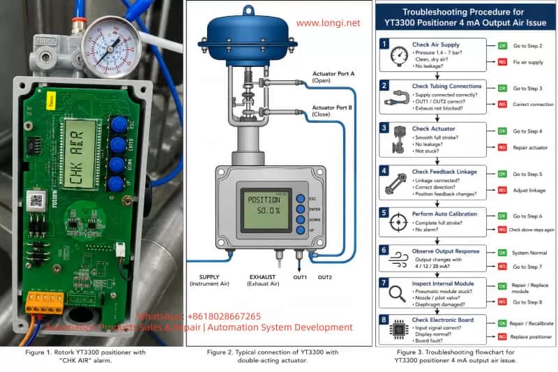
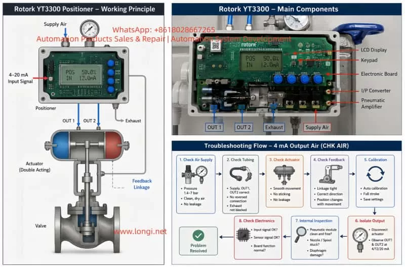
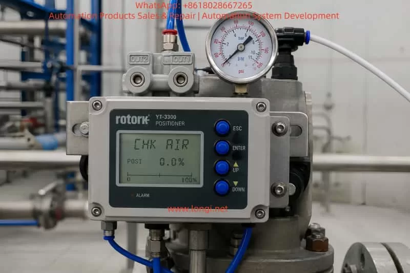
In this case, the device is a Rotork YT3300 smart valve positioner. The customer reported that when only 4 mA is applied, air immediately comes out from output port 1, causing the actuator to move. At the same time, the LCD shows “CHK AIR”.
This is not normal. It means the positioner is not forming a stable closed-loop control between the input signal, pneumatic output, actuator movement, and position feedback. The problem may come from the air supply, tubing connection, actuator direction, feedback linkage, calibration data, internal pneumatic module, or electronic control circuit.
2. How the Rotork YT3300 Works
The YT3300 receives a 4–20 mA signal from the control system. It compares the target valve position with the actual valve position detected by its feedback mechanism. If the valve is not at the requested position, the positioner increases or decreases pneumatic output until the actuator reaches the target position.
The basic logic is:
Control system sends 4–20 mA signal.
Positioner calculates the target valve position.
Feedback mechanism detects actual valve position.
Positioner compares target and actual position.
If correction is needed, it adjusts pneumatic output.
The actuator moves the valve.
The positioner stops adjusting when the valve reaches the target.
Therefore, if 4 mA is applied and output port 1 immediately releases strong air pressure, the positioner may be trying to correct a position error, or the pneumatic output may be uncontrolled due to internal or external faults.
3. Meaning of “CHK AIR”
The display message “CHK AIR” generally indicates that the positioner wants the air supply or pneumatic circuit to be checked. It does not always mean that there is no air supply. It may also appear when the positioner sends a pneumatic control command but does not see the expected valve movement through the feedback signal.
Possible reasons include:
Insufficient air pressure.
Unstable air supply.
Air supply port and output port connected incorrectly.
OUT1 and OUT2 connected in reverse.
Actuator diaphragm leakage.
Actuator or valve stuck mechanically.
Internal pilot valve or pneumatic amplifier stuck.
Nozzle or restriction blocked.
Feedback lever not moving correctly.
Wrong actuator action setting.
Auto calibration not completed.
Positioner parameters not matching the valve and actuator.
In this case, because air comes directly from output 1 at 4 mA and the display shows “CHK AIR”, the positioner is very likely unable to control the pneumatic output correctly.
4. Possible Cause 1: Air Supply Pressure or Air Quality Problem
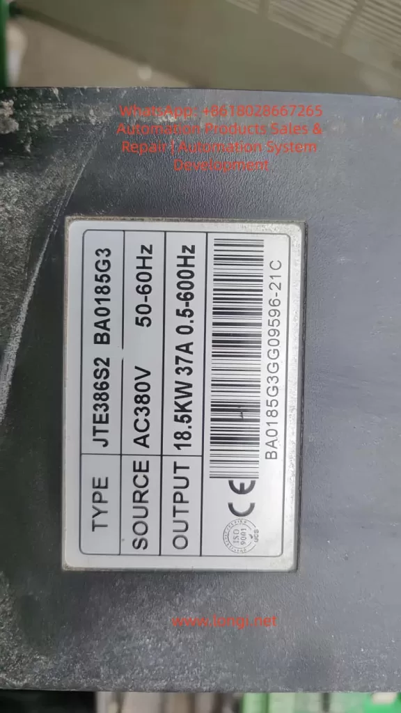
The YT3300 requires clean, dry, and stable instrument air. The nameplate indicates a supply pressure range of approximately 0.14–0.7 MPa, equal to about 1.4–7 bar.
If the air pressure is too low, the actuator may not move correctly and the positioner may show “CHK AIR”. If the pressure is too high, the pneumatic output may become too aggressive and unstable. If the air contains water, oil, rust, or dust, the internal pneumatic amplifier, nozzle, restriction, or valve spool may become blocked or stuck.
The following checks should be done first:
Check the pressure regulator outlet pressure.
Observe whether the pressure drops during actuator movement.
Drain the filter bowl and check for water or oil.
Make sure the air source is connected to the supply port, not to OUT1 or OUT2.
Use clean instrument air for testing if possible.
Check all pneumatic fittings for leakage.
Many positioner faults are caused by poor air quality. If dirty air enters the positioner, cleaning the external tubing alone will not solve the problem. The internal pneumatic module may already be contaminated.
5. Possible Cause 2: Wrong Pneumatic Tubing Connection
Wrong tubing connection is a very common cause of this type of fault.
For a single-acting actuator, usually only one output port is used. For a double-acting actuator, OUT1 and OUT2 are connected to two different actuator chambers. If OUT1 and OUT2 are reversed, the valve may move in the opposite direction from what the positioner expects.
In that situation, the positioner tries to correct the valve position, but the valve moves in the wrong direction. The positioner then increases output even more, causing strong air output and possible alarm.
The following must be confirmed:
Is the actuator single-acting or double-acting?
Is the valve air-to-open or air-to-close?
Should 4 mA mean fully closed or fully open?
Where is OUT1 connected?
Where is OUT2 connected?
Is the supply air connected to the correct supply port?
Is the exhaust port blocked?
If the customer only says “air comes out from OUT1 at 4 mA”, that alone is not enough to confirm the positioner is damaged. The actuator type, valve action, and tubing connection must be checked first.
6. Possible Cause 3: Lost or Incorrect Calibration
A smart positioner must be calibrated after installation. It needs to learn the valve’s zero position, full stroke position, feedback range, movement direction, and actuator response.
If the calibration data is lost or wrong, the positioner may misunderstand the actual valve position. For example, it may think the valve is still far away from the requested 4 mA position, so it continues to output air.
Common symptoms of wrong calibration include:
Valve not closed at 4 mA.
Valve not fully open at 20 mA.
Valve moves in the wrong direction.
Valve hunts or oscillates around the target position.
LCD shows air or stroke-related alarm.
Auto calibration fails.
Displayed valve position does not match actual valve position.
Before recalibration, the following conditions must be satisfied:
Air supply is clean and stable.
Tubing is connected correctly.
Actuator is not stuck.
Feedback linkage is installed correctly.
Valve can move through the full stroke.
Input signal is stable.
No major leakage exists.
If these conditions are not met, auto calibration may fail or store incorrect data again.
7. Possible Cause 4: Feedback Lever or Position Feedback Problem
The positioner does not control the valve only by the 4–20 mA signal. It must also receive correct position feedback from the valve stem or actuator shaft.
If the feedback linkage is loose, disconnected, reversed, or outside its mechanical range, the positioner will not know the real valve position. It may keep outputting air because it believes the valve has not reached the target.
Typical feedback-related problems include:
Valve moves but the position display does not change.
Position display changes in the opposite direction.
Feedback lever is loose.
Linkage is stuck.
Feedback angle is too large or too small.
Lever hits mechanical limit before full valve travel.
Auto calibration cannot complete the stroke.
The customer should check whether the valve stem moves when air is applied, and whether the LCD valve position changes accordingly. If the actuator moves but the display does not follow, the feedback mechanism is the first suspect.
8. Possible Cause 5: Actuator or Valve Mechanical Problem
The positioner may be good, but the actuator or valve may be mechanically stuck.
If the valve stem is jammed, the actuator diaphragm is leaking, the cylinder seal is damaged, or the valve packing is too tight, the positioner may continuously increase air output while the valve does not move properly. This can also trigger “CHK AIR”.
Mechanical causes include:
Actuator diaphragm rupture.
Cylinder seal leakage.
Broken or weak spring.
Valve stem corrosion.
Packing gland too tight.
Valve plug stuck by process deposits.
Linkage looseness.
Mechanical stop incorrectly adjusted.
Actuator internal wear.
To test this, disconnect the positioner output and apply controlled air directly to the actuator. The valve should move smoothly from closed to open and back again. If direct air operation is not smooth, the actuator or valve body must be repaired before working on the positioner.
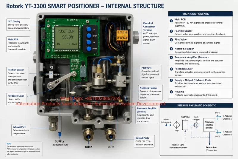
9. Possible Cause 6: Internal Pneumatic Module Fault
If air supply, tubing, actuator, feedback linkage, and calibration are all correct, but OUT1 still releases air uncontrollably at 4 mA, the internal pneumatic module is likely faulty.
Inside a smart positioner, the electrical control signal drives a pneumatic control system, such as a nozzle, flapper, pilot valve, pneumatic amplifier, spool, diaphragm, restriction, and exhaust passage. If the internal valve spool is stuck in the supply position, output air may flow continuously regardless of input signal.
Typical signs of internal pneumatic module failure include:
OUT1 keeps supplying air regardless of 4 mA, 12 mA, or 20 mA.
Output does not change logically with input signal.
Air leaks continuously from output or exhaust.
Auto calibration always fails.
There is abnormal internal air noise.
Light tapping changes the output temporarily.
Problem remains after correct calibration.
Common causes include dirty air, water contamination, oil contamination, rust particles, long-term storage, corrosion, damaged diaphragm, or aged internal seals.
If this is confirmed, the pneumatic module, pilot valve, diaphragm, nozzle assembly, or whole positioner may need repair or replacement.
10. Possible Cause 7: Electronic Board Fault
Electronic board failure is possible, but it should not be the first conclusion. In many real cases, pneumatic and mechanical problems are more common than electronic failure.
Electronic-related problems may include:
4–20 mA input detection fault.
A/D conversion failure.
Position sensor signal fault.
Electropneumatic driver fault.
Parameter memory failure.
Keypad or LCD abnormality.
Water ingress or corrosion in wiring chamber.
Signs of electronic fault include:
LCD display abnormal.
Buttons not responding.
Input current changes but display does not change.
Valve position value jumps randomly.
Positioner restarts repeatedly.
Parameters cannot be saved.
Calibration always fails at the same step.
No correct control signal is sent to pneumatic module.
If another identical positioner is available, the fastest method is cross-testing. If the fault follows the electronic board, the board is faulty. If the fault follows the pneumatic module, the problem is pneumatic.
11. Recommended Troubleshooting Procedure
For this fault, the recommended sequence is:
First, confirm the valve and actuator type.
Find out whether the actuator is single-acting or double-acting.
Confirm whether the valve is air-to-open or air-to-close.
Confirm whether 4 mA should mean closed or open.
Second, check the air supply.
Confirm pressure is within the correct range.
Drain the filter regulator.
Check for water, oil, and dirt.
Make sure pressure remains stable during movement.
Third, check tubing.
Confirm supply, OUT1, OUT2, and exhaust connections.
Make sure there is no reversed or wrong connection.
Fourth, check the actuator.
Operate the actuator directly with controlled air.
Confirm smooth full-stroke movement.
Fifth, check feedback.
Move the valve and verify that the positioner display changes correctly.
Confirm feedback direction and mechanical linkage.
Sixth, perform complete auto calibration.
Do this only when air, actuator, tubing, and feedback are confirmed normal.
Seventh, isolate the positioner output.
Disconnect the actuator tubing and observe OUT1 and OUT2 at 4 mA, 12 mA, and 20 mA.
Eighth, inspect the internal pneumatic module or electronic board if the fault remains.
This sequence avoids unnecessary replacement of expensive parts.
12. Information Needed from the Customer for Remote Diagnosis
For remote technical support, the customer should provide the following:
Clear photo of the positioner nameplate.
Clear photo of all pneumatic tubing connections.
Video showing pressure gauge during operation.
Video at 4 mA, 12 mA, and 20 mA.
Video showing valve stem or actuator movement.
Photo or video of feedback linkage.
Information on whether the actuator is single-acting or double-acting.
Information on whether the valve is air-to-open or air-to-close.
Video of auto calibration until the alarm appears.
Video of OUT1 and OUT2 output with actuator tubing disconnected.
These details are essential. Without them, it is easy to mistake a tubing or calibration problem for a damaged positioner.
13. Important Safety Notes
Do not increase air pressure blindly.
“CHK AIR” does not always mean the pressure is too low. Increasing pressure may cause violent valve movement.
Do not perform auto calibration while the valve is connected to a live process unless the process allows full valve travel.
Do not force the valve mechanically during diagnosis.
Do not replace the electronic board before checking air supply, tubing, actuator, and feedback.
Do not continue testing with dirty or wet air. It may further damage the pneumatic module.
Always confirm the required fail-safe position of the valve before changing parameters.
14. Repair Decision
If the problem is caused by air pressure, tubing, feedback linkage, or calibration, repair is usually simple and does not require replacing the positioner.
If the actuator or valve is stuck, the actuator or valve body must be repaired first.
If the internal pneumatic module is contaminated or stuck, the pilot valve, pneumatic amplifier, diaphragm, nozzle, or related seals may need cleaning or replacement.
If the electronic board or position sensor is faulty, the electronic module may need replacement, followed by complete calibration.
If the positioner is old, heavily contaminated, or both pneumatic and electronic sections are damaged, replacing the complete positioner may be more economical and reliable.
15. Case Conclusion
In this case, the Rotork YT3300 outputs air from port 1 at only 4 mA and shows “CHK AIR”. The most likely causes are:
Wrong air tubing or actuator action configuration.
Lost or incorrect calibration.
Feedback linkage problem.
Actuator or valve mechanical problem.
Internal pneumatic module stuck or contaminated.
The first recommended actions are:
Check air pressure and air quality.
Confirm all tubing connections.
Confirm actuator type and valve action.
Check whether the feedback display follows valve movement.
Perform complete recalibration only after the above items are correct.
If the output remains uncontrolled, inspect the internal pneumatic module.
The key point is that this fault should not be treated only as an electronic failure. A valve positioner is a closed-loop electropneumatic control device. The input signal, pneumatic output, actuator movement, and feedback signal must all match each other. If any one of these links is wrong, the positioner may output air continuously and show an air-related alarm.
A systematic troubleshooting method is the fastest and safest way to solve this type of Rotork YT3300 fault.