
1. Overview of the Fault
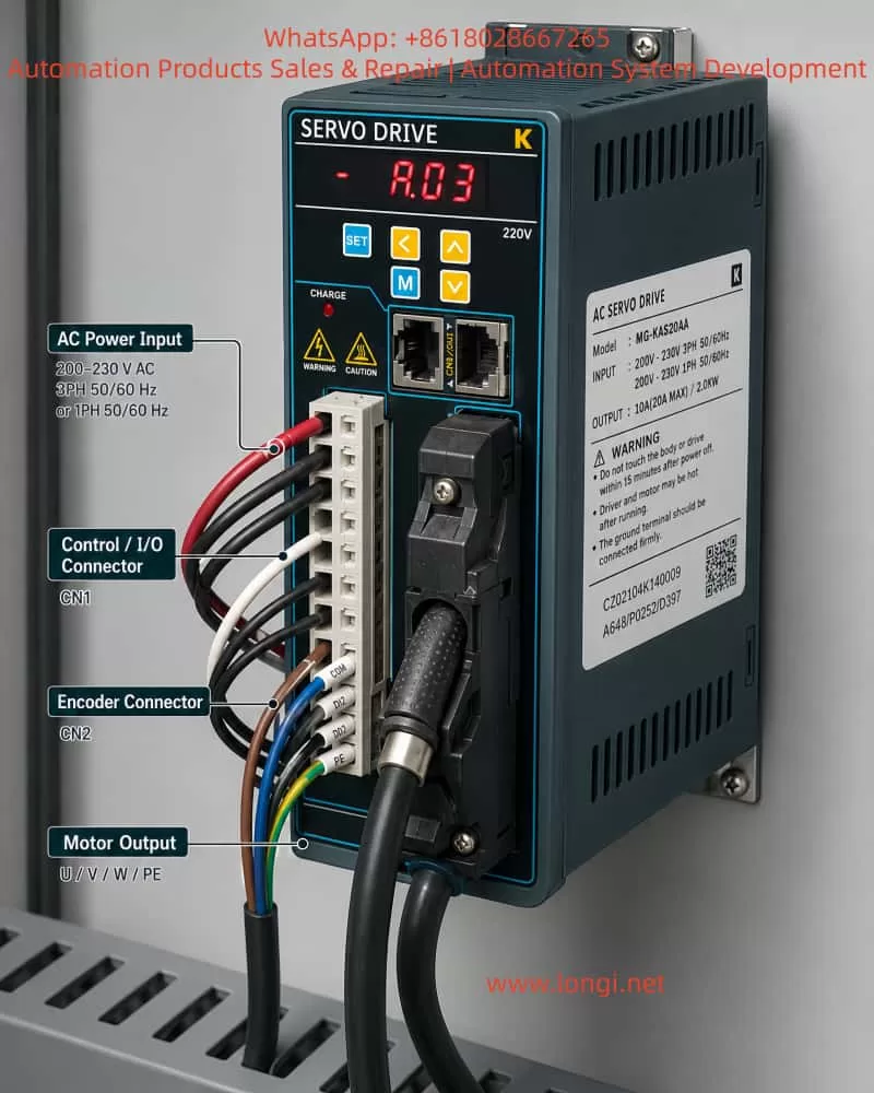
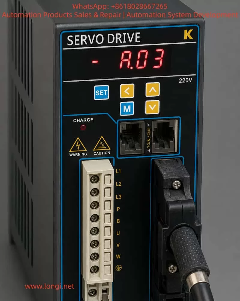
In industrial automation, servo drives are essential for precise control of position, speed, and torque. Based on user reports and inspection images (Attachments 1 and 2), the MG-KAS20AA K-series AC servo drive exhibits the “A.03” alarm code. This code appears on the front panel digital display (Image 2), and the drive fails to rotate, halting the connected mechanical load.
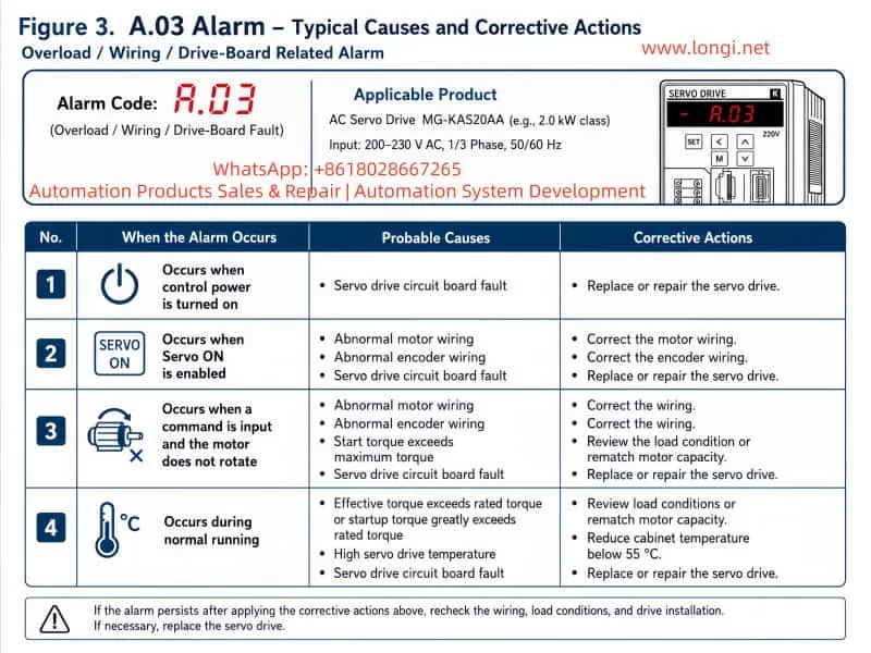
According to the K Series AC Servo Drive User Manual (2017 Engineer Edition V3.0), Chapter 7 and Appendix C, the A.03 alarm falls under overload/torque anomaly faults, primarily associated with:
- Servo drive circuit board faults
- Motor wiring issues
- Encoder signal errors
- Load torque exceeding the drive’s limits
Images show U/V/W motor terminals correctly connected, CN1/CN2 encoder interfaces installed, and PE properly grounded, yet the A.03 alarm persists. This indicates the fault is likely related to the drive board or signal compatibility rather than simple wiring issues.
2. Fault Trigger Conditions
Based on the manual, A.03 may be triggered in the following scenarios:
| Scenario | Trigger Condition | Possible Cause | Recommended Action |
|---|---|---|---|
| Servo ON | Motor does not rotate | Motor wiring abnormality, encoder wiring issue | Inspect and correct motor and encoder wiring |
| Command input | Servo motor unresponsive | Start-up torque exceeds maximum | Adjust load conditions or re-evaluate motor capacity |
| Normal operation | Drive reports A.03 | High internal temperature of servo drive | Reduce drive temperature below 55℃, verify cooling system |
| Any operation | Drive board fault | Drive power module or control board malfunction | Replace servo drive or repair circuit board |
Given the images, the drive reports A.03 under normal power and command input. Hence, drive board or power module failure is the primary suspected cause.
3. Detailed Fault Diagnosis Steps
3.1 Visual Inspection and Wiring Verification
- Power Check
- Verify L1/L2/L3 terminals receive 220V three-phase within ±15%.
- Confirm L1C/L2C control voltage is stable.
- Motor Wiring
- U/V/W terminals correspond to the drive terminals.
- Measure resistance across phases; check for open or short circuits.
- Grounding and Shielding
- PE terminals connected to drive, motor, and cabinet.
- Encoder shield connected to the chassis.
3.2 Encoder Signal Check
Per Manual Section 3.4:
- CN1: Axis A encoder
- CN2: Axis B encoder
Procedure:
- Measure A/B phase signals with an oscilloscope.
- Verify PG pulse output matches user parameter settings.
- Ensure IN1~IN8 input allocation (P□509~P□512) is correct.
- Confirm wiring length and shield integrity (max 3m for command input, max 20m for feedback).
Faulty encoder signals may mislead the drive’s load detection and trigger A.03.
3.3 Drive Board and Power Module Inspection
Manual 7.2.3 highlights common failure points:
- Power Modules (IGBTs/MOSFETs)
- Shorted or open MOSFETs can trigger overcurrent protection (A.03).
- Measure U/V/W terminal resistances offline; check MOSFETs.
- Drive Temperature
- Overheating or sensor failure can cause A.03.
- Use infrared thermometer to monitor PCB temperature (<55℃).
- Control Board
- MCU or logic faults may prevent overload signal processing.
- Check for burnt components or swollen capacitors; replace control board if needed.
3.4 Load Evaluation
A.03 may also result from excessive load torque:
- Load inertia exceeding 5× motor inertia.
- Mechanical resistance or over-torque beyond rated motor torque.
- Aggressive start/stop conditions causing current peaks.
Mitigation:
- Inspect load bearings and couplings for jamming.
- Measure mechanical torque against motor rating.
- Adjust dynamic braking or P-OT / N-OT limit parameters.
3.5 Software and Parameter Verification
- Check user parameters P□□□: torque limit, load inertia, and travel limits.
- Confirm control mode (position/speed/torque) matches mechanical load.
- For absolute encoders, ensure F□009/F□010 settings are correct.
4. Fault Handling and Recovery
- Immediate Measures
- Power down for at least 15 minutes to discharge capacitors.
- Inspect cooling and airflow.
- Wiring and Encoder Verification
- Cross-check terminals per manual 3.1–3.4.
- Confirm encoder signals via oscilloscope.
- Circuit Board or Module Maintenance
- If wiring and encoder are correct, replace power modules or control board.
- Alternatively, send to manufacturer for repair.
- Parameter and Load Adjustment
- Ensure user parameters are within safe limits.
- Adjust load or enable torque compensation to reduce peak currents.
- Long-term Protection
- Maintain drive environment below 45℃.
- Avoid high humidity, dust, or corrosive gases.
- Ensure proper PE grounding.
- Inspect encoder and motor connections periodically.
5. Conclusion
The A.03 alarm on K-series AC servo drives indicates overload/torque anomaly, caused by:
- Drive board or power module failure
- Motor wiring or encoder signal issues
- Load exceeding motor capacity
- Overheating or insufficient cooling
Resolution Principle:
- Inspect wiring and connections first.
- Verify encoder signals and input/output parameter allocation.
- Evaluate load and mechanical conditions.
- Replace drive board or power module if necessary.
Following this systematic approach ensures reliable operation of MG-KAS20AA drives, minimizing downtime and safeguarding industrial automation processes.