1. Fault Overview
WEIHONG CNC control systems are widely used in woodworking engraving machines, panel cutting machines, CNC routers, and woodworking machining centers. Compared with common faults related to VFDs, servo drives, PLCs, limit switches, or pneumatic components, faults inside the CNC controller itself are often more difficult for field technicians to judge correctly. Once the controller fails to start properly, the whole machine cannot perform homing, load machining programs, enable servo axes, or run automatic operation.
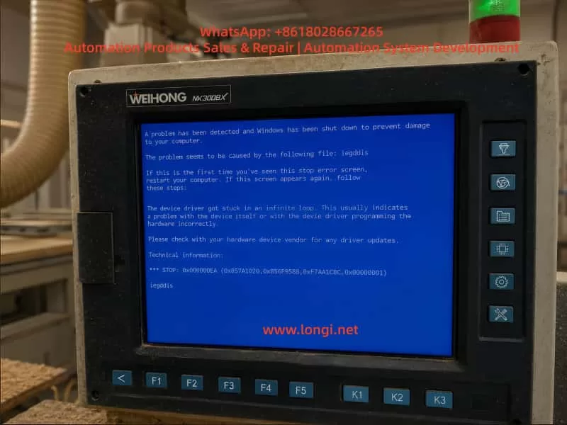
In this case, a woodworking machining center equipped with a WEIHONG NK300BX controller showed a Windows blue screen after power-on. The screen displayed the following message:
A problem has been detected and Windows has been shut down to prevent damage to your computer.
The most important fault information on the screen was:
STOP: 0x000000EA
and the related fault file was:
iegddis
The blue screen also showed the following explanation:
The device driver got stuck in an infinite loop. This usually indicates problem with the device itself or with the device driver programming the hardware incorrectly.
From these messages, it can be determined that this is not a normal CNC machining alarm. It is not a servo alarm, spindle inverter alarm, tool magazine alarm, air pressure alarm, limit switch alarm, or emergency stop alarm. Instead, it is a Windows system crash inside the industrial computer section of the CNC controller.
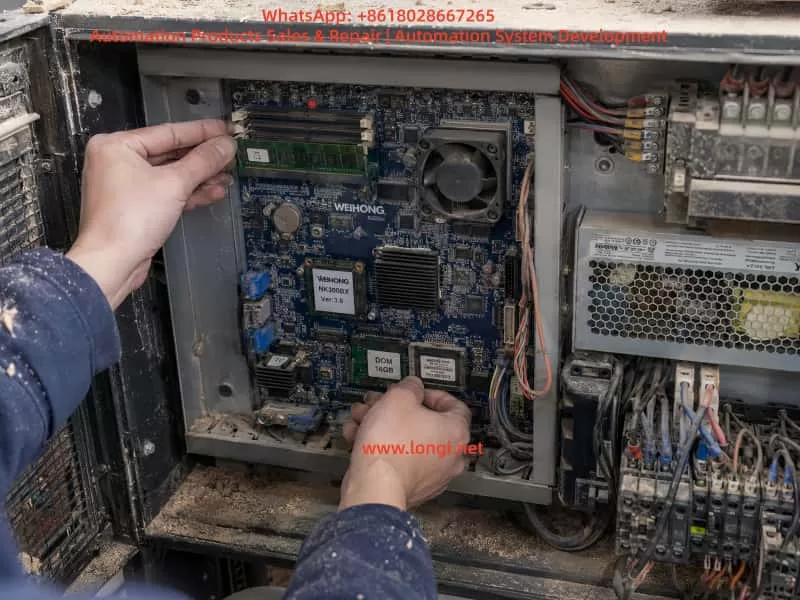
The NK300BX controller is not only a simple operation panel. It normally contains an industrial computer mainboard, system storage device, RAM, display circuit, I/O control interface, CNC control software, and dedicated machine configuration files. Therefore, this type of blue screen fault must be analyzed from the perspective of an industrial PC system, not only from the perspective of ordinary machine electrical faults.
2. Difference Between an NK300BX Blue Screen and a Normal CNC Alarm
In woodworking CNC machines, technicians usually judge faults from alarm messages shown inside the CNC software interface. Typical alarms include emergency stop not released, axis limit triggered, servo not ready, spindle not started, insufficient air pressure, homing failure, tool number error, tool magazine position error, or external input abnormality. These alarms are generated after the CNC software has started normally and detected an abnormal condition from the machine.
The blue screen in this case is completely different. A Windows blue screen means that the underlying operating system has crashed. When this happens, the WEIHONG CNC software cannot continue running, the I/O status cannot be read normally, servo enable signals cannot be controlled properly, spindle control cannot be issued, machining programs cannot be loaded, and homing operation cannot be performed.
Therefore, this type of fault should not be handled as an ordinary machining alarm. Checking the limit switches, emergency stop button, servo drives, spindle VFD, pneumatic valves, air pressure switch, or tool sensor will usually not solve the problem. The correct maintenance focus should be on the internal industrial computer hardware, system disk, display driver, RAM, motherboard chipset, graphics circuit, cooling condition, and power supply stability of the controller.
3. Meaning of STOP 0x000000EA
The Windows blue screen code STOP 0x000000EA generally means that a device driver has become stuck in an infinite loop. Windows stops the system to prevent further damage or a complete lock-up. The explanation shown on the blue screen already gives an important clue: the device driver is unable to correctly control the hardware, or the hardware itself is not responding correctly.
In this specific case, the fault file shown is iegddis. This file name is generally related to the Intel integrated graphics/display driver. Many early industrial PC mainboards use Intel chipsets and integrated graphics. During Windows startup and operation, the display driver is responsible for screen output, graphical interface refresh, and communication with the display hardware.
If the display driver file is damaged, the integrated graphics chipset is abnormal, the RAM reads data incorrectly, or the system disk has damaged files, the system may report this kind of blue screen.
For a CNC controller, this type of problem may appear in different ways. Some machines may occasionally show a blue screen and work again after restart. Some may repeatedly show the blue screen and never enter the WEIHONG operation interface. Some may start normally but crash after running for a period of time due to heat, vibration, unstable power supply, or file read errors. Different symptoms point to different possible root causes.
4. Possible Causes
4.1 Damaged Windows System Files or Display Driver
This is one of the most common causes. Woodworking CNC controllers often operate in dusty environments and may experience improper shutdowns, unstable power supply, sudden power loss, or long-term lack of system maintenance. These conditions can damage Windows system files.
If the damaged file is related to the display driver, graphics initialization, or Windows startup, the machine may show STOP 0x000000EA during startup.
If the machine shows the same blue screen every time it starts, and the fault file is always iegddis, the probability of system file damage or display driver damage is high. In this situation, it is not reasonable to immediately replace servo drives or spindle inverters, because external actuators normally do not directly cause a Windows display driver blue screen.
4.2 Aging System Disk, DOM, CF Card, or Hard Disk
Many WEIHONG controllers and early industrial CNC systems use DOM electronic disks, CF cards, IDE hard disks, SATA industrial disks, or small industrial storage modules as the system storage device. After years of operation, these storage devices may develop bad sectors, slow reading speed, file corruption, missing system files, or damaged partitions.
When the system disk becomes weak, Windows may fail to read the display driver file correctly during startup. It may also read corrupted data and then crash. Common symptoms include slow startup, occasional “system not found” messages, missing file warnings, CNC software freezing, machining programs failing to save, frequent crashes, or repeated blue screens.
For CNC controller maintenance, the system disk is a very important inspection point. The system disk does not only contain Windows. It also contains the CNC software, controller card driver, machine parameters, manufacturer configuration files, tool magazine logic, I/O mapping, axis settings, and sometimes authorization files. If the system disk is completely damaged without backup, recovery becomes much more difficult.
4.3 Poor RAM Contact or Damaged RAM
Woodworking machines operate in environments with dust, vibration, temperature changes, and sometimes humidity. The RAM module inside the controller may become loose, oxidized, or contaminated with dust. Poor RAM contact can cause system files to load incorrectly, drivers to execute abnormally, and the graphical interface to crash.
RAM faults do not always produce the same blue screen code. Sometimes the machine fails during startup. Sometimes it freezes during operation. Sometimes the CNC software crashes after entering Windows. If cleaning and reseating the RAM temporarily solves the problem, poor contact is likely. If replacing the RAM completely solves the issue, the original RAM should be considered faulty.
4.4 Integrated Graphics or Motherboard Chipset Failure
Because the blue screen points to the display driver, the graphics hardware itself must also be considered. On many industrial mainboards, the graphics function is integrated into the chipset. If the graphics chipset is aging, overheating, poorly soldered, or affected by unstable power supply, the display driver may fail to control the hardware correctly, resulting in the “infinite loop” blue screen.
This possibility becomes more likely if the fault still appears after system restoration, system disk replacement, and display driver reinstallation. If the controller has been used for many years, if the cooling fan has stopped, if the heat sink is full of dust, or if motherboard capacitors are aging, the probability of motherboard hardware failure increases significantly.
4.5 Poor Cooling and Dust Contamination
The biggest environmental problem for woodworking machines is wood dust. Dust can enter the controller and accumulate on the motherboard, RAM, heat sink, power supply board, and connectors. It reduces cooling efficiency and may also cause slight leakage or corrosion when combined with moisture.
If the CPU, chipset, or graphics section overheats, the system may freeze, show a blue screen, restart automatically, or display abnormal graphics. If the customer reports that the machine works normally when cold but crashes after running for some time, or if the problem becomes more frequent in hot weather, cooling should be checked carefully.
The technician should inspect whether the internal fan is rotating, whether the heat sink is blocked by dust, and whether the motherboard is covered by wood powder.
4.6 Abnormal Controller Power Supply
Although this case mainly points to a display driver problem, the controller power supply should not be ignored. The industrial PC mainboard normally requires stable 5V, 12V, or dedicated power rails. If the power supply is aging, filter capacitors are weak, or ripple is excessive, the system may crash randomly.
A woodworking machine may contain high-interference devices such as spindle VFDs, servo drives, solenoid valves, vacuum pumps, dust collectors, and large motors. Poor grounding, weak shielding, or unstable supply voltage can increase the chance of controller instability.
For an intermittent blue screen, the technician should measure the controller input voltage and internal power supply output. It is also important to observe whether the blue screen appears when the spindle starts, when servo axes move, or when a dust collector or vacuum pump is switched on. If the fault is synchronized with high-power equipment operation, power quality and electrical interference must be investigated.
5. Initial On-Site Diagnosis
When an NK300BX controller shows a blue screen, external electrical components should not be replaced blindly. A correct diagnosis should begin with the blue screen information, timing of the fault, restart behavior, and internal controller condition.
First, record the blue screen code and the file name. In this case, the important information is STOP 0x000000EA and iegddis. This clearly points toward the Windows display driver, graphics hardware, or related system files.
Second, check whether the fault appears every time. If the controller shows the same blue screen at every startup, the system disk, display driver, system files, or motherboard graphics hardware are the main suspects. If the fault appears only occasionally, RAM contact, cooling, power supply, or vibration-related problems should also be considered.
Third, power off the machine completely and wait for several minutes before restarting. If the controller can enter Windows or the WEIHONG CNC interface even once, immediately back up machine parameters, machining programs, and configuration files. Do not continue repeated test starts without backup, because if the system disk is already weak, repeated abnormal shutdowns may make the damage worse.
Fourth, open the controller and check the internal condition. Look for heavy wood dust, stopped fans, swollen capacitors, loose RAM, loose system disk connectors, oxidized terminals, or damaged ribbon cables.
Fifth, if possible, try to enter Windows Safe Mode. If Safe Mode can be entered, the basic hardware may still be functional, and the problem may be related to the display driver or normal startup items. The display driver can be removed or replaced by the standard VGA driver for testing. However, for CNC controllers, random driver installation is not recommended, because an incorrect driver version may affect the CNC software environment or controller card driver.
6. Recommended Repair Procedure
6.1 Back Up Data First
If the controller can still enter the system, the first action should be backup, not repair. Important data includes machine parameters, machining programs, tool magazine parameters, homing parameters, I/O configuration, manufacturer-specific configuration files, WEIHONG software installation package, and license-related files if available.
For woodworking machining centers, even if the control system model is the same, the parameters may be different from one machine to another. Machine stroke, pulse equivalent, home direction, limit polarity, tool magazine logic, vacuum zone control, spindle command method, lubrication output, and pneumatic sequence may all be customized by the machine manufacturer.
If the system disk is damaged and there is no parameter backup, reinstalling the software alone may not restore the machine to working condition. The machine may still need a complete parameter setup and commissioning.
6.2 Clean Dust and Reseat RAM and System Disk
After disconnecting power, open the controller housing and clean the internal dust using dry compressed air or an anti-static brush. Remove the RAM module, clean the gold fingers with alcohol, allow it to dry, and reinstall it firmly. Check whether the DOM, CF card, hard disk, SATA cable, or IDE connector is loose. Reseat the connectors if necessary.
This simple step is very effective in woodworking machinery. Many blue screen, freezing, and startup problems are not caused by completely failed components, but by dust, oxidation, vibration, and poor contact.
6.3 Check Cooling Fan and Motherboard Condition
Check whether the CPU fan and enclosure fan are operating normally. If a fan is stuck, slow, noisy, or not rotating, it should be replaced. Check whether the heat sink is blocked by dust. Inspect the motherboard capacitors for swelling or leakage. Look for overheating marks around the chipset, power section, and display circuit.
If the controller only fails after running for a period of time, use a temperature measuring tool or infrared thermometer to check the CPU, chipset, and power module temperature. If the temperature is too high, solve the cooling problem before doing deeper system repair.
6.4 Test or Replace the System Disk
If the system disk can be removed, make a full disk image backup first. For old CF cards, DOM modules, or hard disks, it is not recommended to repeatedly repair the original disk directly. If the disk is already weak, repair operations may cause further data loss.
A safer method is to clone the original system disk to a new industrial-grade disk and then test the cloned disk. If the cloned disk works normally, the original disk is likely aging or unstable. If the cloning process reports read errors or becomes extremely slow, the original disk condition is probably poor.
6.5 Restore the System Image or Reinstall the CNC Environment
If system files are confirmed to be damaged, the system image may need to be restored. However, an ordinary Windows installation is not enough for a WEIHONG CNC controller. The NK300BX requires dedicated CNC software, hardware drivers, controller card drivers, authorization files, and machine manufacturer parameters.
System recovery should preferably use the original manufacturer image, the same controller model image, or a complete backup image. If no image is available, the equipment manufacturer or WEIHONG system supplier should be contacted for the correct version. Installing a normal Windows system blindly may allow the controller to boot, but the machine may still be unable to move or operate correctly.
6.6 Replace RAM for Cross Testing
If the blue screen is intermittent, the fault code changes, or the system is unstable, replace the RAM with a known good module of the same specification. RAM faults cannot always be judged visually, and they may not always prevent startup. In field repair, cross testing with a known good RAM module is one of the fastest and most practical methods.
6.7 Determine Whether the Motherboard Is Faulty
If cleaning, reseating RAM, replacing the system disk, restoring the system, and reinstalling the display driver do not solve the problem, and the controller still repeatedly shows STOP 0x000000EA with iegddis, the motherboard graphics section or chipset should be strongly suspected.
Motherboard faults may include integrated graphics failure, chipset soldering problems, abnormal motherboard power supply, aging capacitors, or BIOS-related issues. These faults are more difficult to repair on site. Unless professional BGA repair and industrial motherboard repair equipment are available, replacing the same model motherboard or replacing the complete controller is usually more efficient.
7. How to Distinguish This Fault from Servo, VFD, and I/O Faults
When a woodworking machine cannot start, many technicians first suspect the servo drive, spindle inverter, or control wiring. In this case, however, the Windows blue screen appears before the CNC software can run normally. Therefore, external servo drives and VFDs are usually not the direct cause.
External equipment may indirectly affect the controller through electrical noise, grounding problems, or power supply disturbance, but this is different from a normal servo alarm.
The distinction is simple:
If the screen enters the WEIHONG CNC software and shows an axis alarm, emergency stop alarm, limit alarm, spindle alarm, or input/output alarm, it belongs to the CNC control layer.
If the screen directly shows a Windows blue screen with a STOP code and a system file name, it belongs to the industrial computer layer inside the controller.
This case is clearly the second type. The correct repair direction should focus on the controller itself instead of blindly checking the tool sensor, spindle, limit switch, or pneumatic components.
8. How to Explain the Fault to the Customer
When communicating with a woodworking machine customer, it is better to avoid excessive computer terminology. The explanation can be made simple and practical:
This is not a normal machining alarm. It is a Windows blue screen inside the CNC controller. The blue screen code is 0x000000EA, and the related file is iegddis, which is associated with the Intel display driver or graphics hardware. Possible causes include damaged system files, aging system disk, poor RAM contact, motherboard graphics failure, internal dust, overheating, or unstable controller power supply. The first step is to power off the machine, clean the controller, reseat the RAM and system disk, and try to restart. If the controller can enter the system, back up the parameters and machining programs immediately. If the blue screen appears repeatedly, the system disk, Windows image, or controller motherboard needs further repair or replacement.
This explanation helps the customer understand that the problem cannot be solved simply by changing a parameter. The controller itself must be inspected.
9. Preventive Maintenance
To reduce blue screen and freezing faults in WEIHONG CNC controllers, woodworking machines should be maintained regularly. The electrical cabinet and controller should be cleaned periodically. Cooling air channels should be kept clear. The machine should be shut down through the normal procedure whenever possible, instead of switching off power directly.
Important machining programs and machine parameters should be backed up regularly to a USB drive or computer. For older controllers using CF cards, DOM modules, or old hard disks, a system disk image should be made in advance. This is especially important because once the system disk fails completely, recovery may require the original machine manufacturer, and downtime will be much longer.
Good grounding, proper shielding, and stable power supply are also important. The spindle VFD, servo drives, vacuum pump, and dust collector may generate electrical interference. If grounding is poor, the CNC controller may become unstable even if the controller itself is not completely damaged.
10. Conclusion
A WEIHONG NK300BX controller showing a Windows blue screen with STOP 0x000000EA and iegddis is an internal industrial PC system fault, not a normal CNC machining alarm. The problem is usually related to the Intel display driver, Windows system files, system disk, RAM, integrated graphics chipset, cooling condition, or controller power supply stability.
The correct repair principle is to proceed from simple checks to deeper diagnosis. First record the blue screen information. Then clean the controller, reseat RAM and system disk, and check fans and cooling. If the system can still enter Windows, back up parameters and programs immediately. Next, test the system disk, clone or replace it if necessary, restore the system image, or reinstall the correct WEIHONG CNC software environment. If the same 0x000000EA iegddis blue screen remains after system and storage repair, the motherboard graphics section or chipset should be suspected.
For woodworking CNC machine users, the key point is to identify the fault level correctly. A Windows blue screen means the CNC software has already failed to run. The troubleshooting direction should begin with the controller’s internal industrial computer system, not with the common external machine alarms such as servo, spindle, limit switch, or air pressure faults. Correct fault identification can prevent unnecessary parts replacement, reduce downtime, and help restore production faster.