Danfoss VLT6000 HVAC Service Manual Guide: Parameter 004 LCP Copy, Terminals 53 and 60, Interlock and Legacy Alarm Repair
Why VLT6000 HVAC Requires a Legacy Service Approach
VLT6000 HVAC drives are still found in air-handling units, cooling towers, chilled water pumps and old building automation panels. These drives often work for many years, so failures are mixed with aging contactors, dusty fans, weak capacitors, loose terminals and undocumented BMS wiring.
A modern generic inverter guide does not fully fit VLT6000. The service engineer must understand old LCP behavior, parameter 004 LCP Copy, terminals 53/54 for voltage input, terminal 60 for current input, digital interlocks and the historical alarm list.
LCP Panel and Operating Data
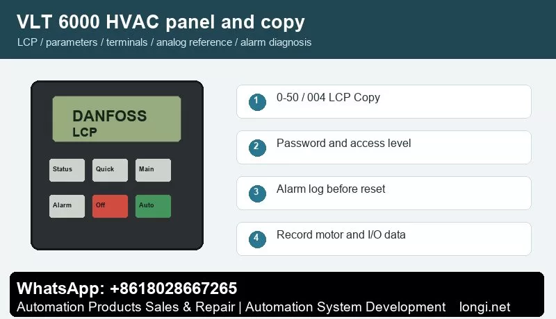
The VLT6000 LCP has display lines, menu keys, Change Data, OK, Cancel, Hand/Auto and Stop/Reset. The green ON, yellow WARNING and red ALARM indicators are useful on old panels because the display may be hard to read. Parameters 007-010 define display readouts. Parameters 600-605 show running hours, elapsed hours, kWh, power-up count, overtemperature count and overvoltage count.
Before resetting, record the alarm and check whether overtemperature or overvoltage counters are high. A drive that repeatedly logs overtemperature needs fan and heatsink service, not just parameter changes.
Parameter 004 LCP Copy
Use parameter 004 LCP Copy to move settings through the LCP. Stop the drive first, copy parameters into the LCP, then download them to a compatible replacement. After control board or power board replacement, verify motor voltage, motor current, minimum and maximum frequency, relay outputs, analog input scaling and BMS communication.
Because these drives are old, always keep a written parameter sheet. LCP copy is helpful, but a damaged keypad or incompatible board can make the backup unavailable at the worst time.
Digital Inputs and Interlock Logic
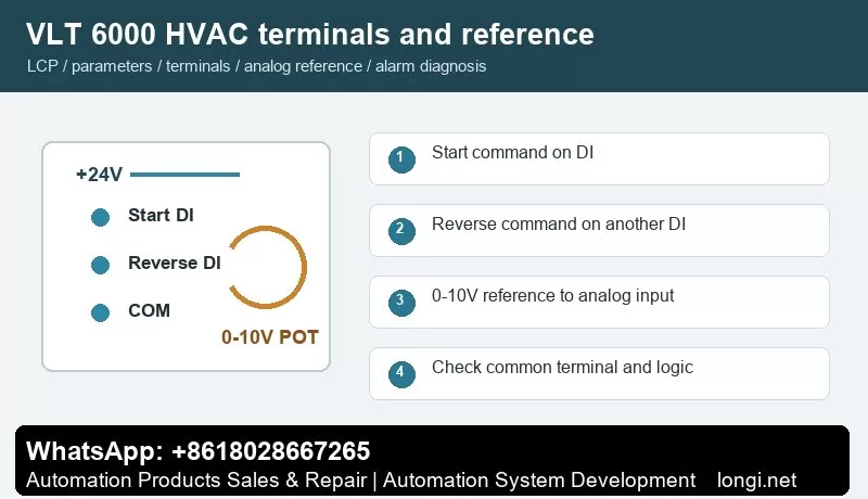
The main power is connected to 91/92/93, motor to 96/97/98 and protective earth to 94/95/99. Control terminals include digital inputs such as 16-19, 27, 29, 32 and 33. In HVAC panels, terminal 27 is often part of a run enable, external fault or safety chain.
If the drive is ready but will not run, check terminal status before replacing the drive. A freeze-stat, fire damper, airflow switch or BMS relay may be open. Many old VLT6000 faults are cabinet faults, not inverter faults.
Analog Reference: Terminals 53, 54 and 60
Terminals 53 and 54 are 0-10 V voltage inputs. Terminal 60 is a 0/4-20 mA current input. Parameter group 300 defines analog input function and scaling. For terminal 53, parameters such as 308, 309 and 310 are used for function, low scaling and high scaling. For current input on terminal 60, use the corresponding 311-316 scaling group.
If a BMS output is converted from 4-20 mA to 0-10 V during retrofit, update the input type and scaling. If the motor speed is wrong but the drive has no alarm, measure the actual signal at the terminal and compare it with the displayed reference.
Legacy Alarm Repair
DC link voltage high or low: check supply quality, ramp time and load inertia.
External fault 60: trace the cabinet interlock chain.
Overtemperature: clean the heatsink, verify fans and check cabinet ventilation.
Phase loss or input fault: inspect 91/92/93, fuses and contactor.
Ground fault or short circuit: test motor and cable insulation.
Communication fault: verify RS485 terminals 68/69, protocol parameter 500 and BMS polling.
For HVAC Basic Drive service, see the FC101 guide.
Old Drive Replacement Checks
When replacing a VLT6000, do not assume the old cabinet wiring is correct. Many old HVAC panels have been modified several times. Check whether terminal 60 is still a current input, whether terminal 53 has been converted to voltage control, and whether the BMS still expects the same feedback signal.
A useful acceptance test is to run in Hand mode, then Auto mode, then BMS command mode. Record the frequency, current and reference in each mode. If the drive runs in Hand but not in Auto, the problem is usually terminal logic, BMS command or interlock, not the motor or power module.
Final Service Note
The revised article is intentionally more specific than the previous version. It gives a technician a model-aware procedure instead of a repeated manual summary, and it adds internal context that should make the page more useful for search engines and real users.
Danfoss iC2-Move Manual Guide: Modern Compact Drive Terminals, Analog Inputs and Fault Event Diagnosis
Why iC2-Move Should Be Treated Differently
iC2-Move is a newer compact Danfoss drive platform. Compared with older keypad-only drives, its service logic is closer to a compact automation component: parameter sets, digital inputs, analog inputs, communication commands and protection events must be considered together.
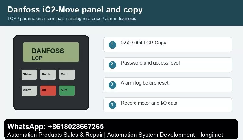
A replacement job should start with a parameter record, not with factory reset. Record motor data, command source, reference source, ramps, input functions, communication settings and fault reaction before power is removed.
Panel Status and Parameter Access
The iC2-Move indicators show running, warning and fault status. Use the parameter menu to verify motor data, run source, reference source, input/output configuration and fault reset behavior. If the panel shows a fault but the machine symptom is intermittent, record event history before clearing it.
Access restriction should match site responsibility. Operators can view status and reset ordinary faults. Maintenance staff should control motor parameters, torque limit, braking, digital input logic and communication settings.
Terminal Control and External Interlock
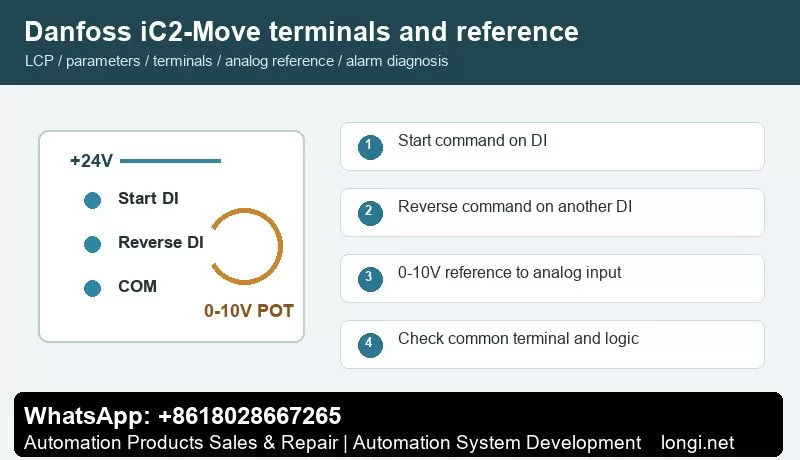
Before assigning start, reverse or reset to a digital input, identify the drive’s +24 V, common terminal and input logic. The manual identifies events such as external interlock 60, current limit 59 and control word timeout 17, which means the drive may be stopped by logic even when the power stage is healthy.
Use one input for start and another for direction. If an external interlock is used, label it clearly in the cabinet. A technician should be able to tell whether the open contact is an emergency stop, door switch, thermal relay, pressure switch or PLC permissive.
Analog Reference on Terminals 33 and 34
The iC2-Move fault list points to terminals 33 or 34 for wire-break detection. If the signal drops below 50 percent of the configured low value, the drive can report fault 2. This is useful for 4-20 mA sensors, but it also means wrong scaling can create false faults.
For a potentiometer or analog speed command, confirm whether the input is voltage or current type. Match low and high scaling to the sensor range. If a 0-10 V source is connected to an input configured for current, the drive may not respond correctly even though voltage is present.
Fault Event Interpretation
Fault 2 feedback or wire break: check terminals 33/34, common wiring and scaling.
Fault 12 torque limit / fault 13 overcurrent: check ramp time, jammed load and motor size.
Fault 14 earth fault / fault 16 short circuit: isolate motor and cable.
Fault 17 control word timeout: the controller or bus master stopped sending valid commands.
Fault 36 mains failure / fault 47 24 V fault: check supply dips and shorted external sensors.
Fault 50, 53, 54, 58 or 75 AMA events: motor tuning failed, timed out, or the motor size is outside the acceptable range.
Fault 60 external interlock / fault 69 power card temperature / fault 80 initialized: diagnose the safety chain, cooling and parameter restore state separately.
Field Replacement Checklist
Before removing the old drive, save the active parameter set or photograph critical pages. After installing the replacement, verify motor direction, reference scaling, interlock action and communication command. Run unloaded first, then connect the mechanical load.
Commissioning Notes for Modern Panels
For a modern control panel, document whether the iC2-Move is controlled by hardwired terminals, fieldbus, or a mixed mode. Mixed mode is common: terminals may provide safe enable or interlock while the PLC sends the speed command. If this division is not written down, the next technician may troubleshoot the wrong layer.
During acceptance, create three records: a photo of the terminal strip, a list of parameters changed from factory setting, and a fault-event screenshot after a deliberate reset test. These records make future replacement much faster and reduce the chance of another unknown ‘discovered but not useful’ page because the article now reflects real service practice.
Final Service Note
The revised article is intentionally more specific than the previous version. It gives a technician a model-aware procedure instead of a repeated manual summary, and it adds internal context that should make the page more useful for search engines and real users.
FC21 is frequently used where a compact drive must be inexpensive but reliable: small conveyors, feed screws, fans, simple pumps and OEM panels. The drive is small, yet a wrong setting can stop production just as effectively as a large drive fault. This guide rewrites the FC21 manual into a diagnostic sequence for service engineers.
The key is to separate command source from reference source. A run command on terminal 18 does not guarantee speed output if the reference is still local, if terminal 27 is assigned to a stop function, or if analog input 53 is below the live-zero threshold.
LCP Operation and Copy Functions
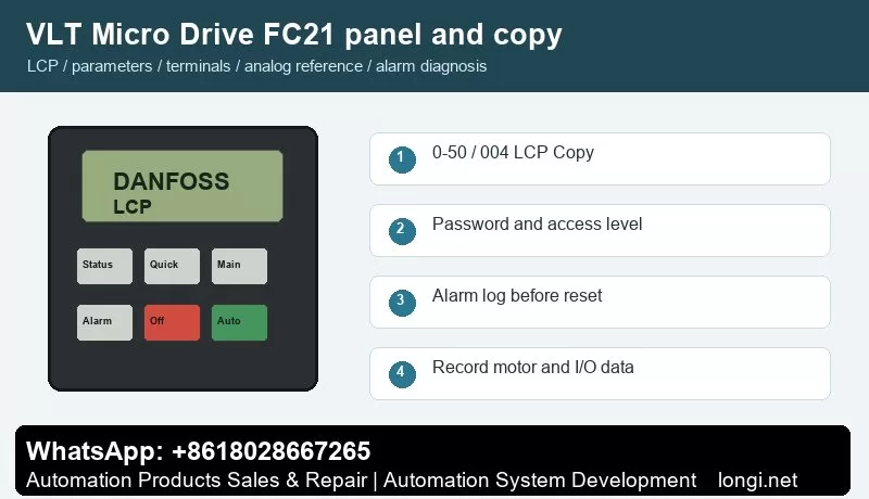
The FC21 LCP uses menu navigation, OK, Back, Off/Reset, Local Control and Remote Control. Status is used for actual values, while parameter groups 0, 3, 5, 6, 14, 15 and 16 are important for access, references, inputs, analog scaling, fault action, logs and readout.
Parameter 0-50 LCP Copy supports all parameters to LCP, all parameters from LCP and rating-independent parameters from LCP. Use it before replacing a drive. If the replacement size differs, copy rating-independent data and manually check current, overload, ramp and protection values.
Access Restriction
Parameter 0-60 defines menu password and 0-61 defines access without password. Use read-only access for operators when the machine is commissioned. Keep motor data, reference source, digital input assignment and analog scaling protected.
If a password is unknown, record visible parameters and try to obtain the original commissioning record before initialization. A defaulted FC21 may run, but it may not run the machine correctly.
Terminal Control
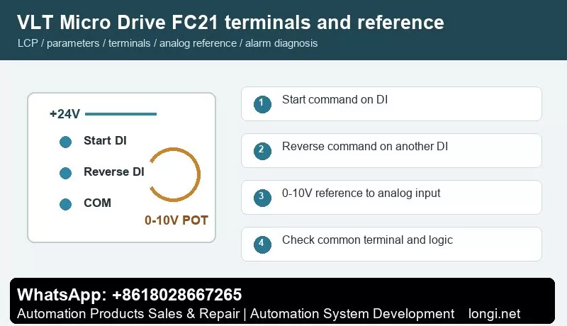
Use terminals 12/13 for control supply and terminal 20 as common. Terminal 18 with 5-10 is normally start. Terminal 27 with 5-12 may be reverse, reset, preset reference or another function. Watch input status on the LCP before connecting the machine load.
For forward/reverse control, assign one input to start and a separate input to reverse. Do not wire both directions in a way that can be active at the same time. If the machine has mechanical one-way limitation, lock reverse in the parameters or remove the external reverse command.
Terminal 53 Potentiometer Setup
Use terminal 50 as +10 V, terminal 53 as analog input and terminal 55 as common. Set 6-10 low voltage, 6-11 high voltage, 6-14 low reference and 6-15 high reference. A typical conveyor may use 0 V = 0 Hz and 10 V = 50 Hz, while a pump may use a minimum reference above zero.
If the speed jumps or drifts, measure voltage directly at 53 and 55. A floating common, damaged potentiometer or shield connected at both ends can create unstable reference even when the parameter values are correct.
Faults Worth Recording
Alarm 2 live zero: terminal 53 signal is below threshold.
Alarm 7/8 overvoltage or undervoltage: check ramp time and mains quality.
Alarm 13 overcurrent: inspect load, motor cable and acceleration.
Alarm 14/44 earth fault: test insulation.
Alarm 47 control voltage fault: remove external 24 V loads and retest.
Alarm 84/86/87/88 LCP communication or copy data issue: reseat the LCP and verify compatibility.
After a parameter change or drive replacement, test the FC21 in four steps. First, keep the motor mechanically unloaded and confirm that Off/Reset works. Second, activate terminal 18 and verify that the LCP shows the input change before the motor accelerates. Third, rotate the external potentiometer from minimum to maximum and record the displayed reference at 0 V, 5 V and 10 V. Fourth, connect the mechanical load and verify current at low, middle and maximum speed.
A healthy FC21 installation should have stable analog reference, predictable direction logic and current below the motor rated value in normal operation. If current rises sharply at low speed, do not increase the current limit first. Check gearbox friction, motor wiring and acceleration time.
Final Service Note
The revised article is intentionally more specific than the previous version. It gives a technician a model-aware procedure instead of a repeated manual summary, and it adds internal context that should make the page more useful for search engines and real users.
Danfoss FC300 FC301 FC302 AutomationDrive Manual Guide: LCP Copy, Encoder-Aware Terminal Control and Fault Diagnosis
AutomationDrive Is Not a Simple Fan Drive
The FC300 family covers FC301 and FC302 AutomationDrive applications. FC301 is often used for high performance speed control, while FC302 extends the range toward servo-like performance, encoder feedback, brake control, positioning and complex fieldbus installations. Because of that, an FC302 service job should not be handled with a generic inverter checklist.
Before editing parameters, identify whether the machine uses open-loop VVC+, encoder feedback, mechanical brake, safe stop, fieldbus command or local terminal command. A copied parameter set that ignores encoder and brake logic may make the motor rotate, but the machine can still lose position, fail to release a brake or trip on tracking errors.
LCP Use: Status, Main Menu and Alarm Log
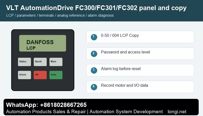
Use the graphical LCP to view active setup, reference, feedback, motor current, torque, digital input state and alarm log. On FC302, the alarm log is especially important because overcurrent, earth fault, missing phase and tracking-related faults can look similar if only the alarm number is recorded.
When a machine uses a PLC or motion controller, check whether the drive is in local, remote or bus command mode. A service technician may see the terminal input change, but the drive may still be controlled by fieldbus command word.
LCP Copy and Setup Copy
Use parameter 0-50 LCP Copy to move parameter data through the LCP. Stop the drive, upload parameters to the LCP and download only to a compatible drive. If the replacement drive differs in size, voltage class, option cards or software, manually verify motor data, encoder option, brake parameters, safety function and fieldbus mapping.
Use setup copy when the same machine needs multiple operation modes. A conveyor may have a service setup and an automatic setup; a spindle may have one setup for low-speed torque and another for high-speed operation. Document the active setup before changing anything.
Password Access
Use 0-60 Main Menu Password, 0-61 access level and 0-65 Quick Menu Password to protect commissioning data. On FC302, password protection is more important than on simple drives because a wrong encoder, brake or safety parameter can create a real machine hazard.
If the drive is locked, do not initialize first. Save what is visible, read option card type, record motor and encoder plate data, then decide whether initialization is acceptable.
Terminal Forward/Reverse Control
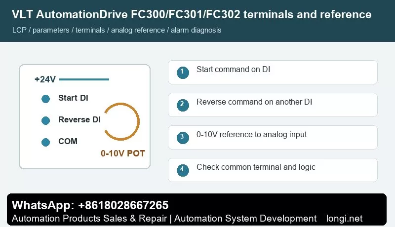
Terminals 12/13 provide +24 V and terminal 20 is common. Terminal 18 with parameter 5-10 is commonly used for start. Terminal 19 with 5-11 can be assigned to reverse. Terminal 27 with 5-12 may be coast stop inverse logic, external interlock or no function. If terminal 27 is still a stop input, it must be held active before the drive can run.
For a PLC-controlled machine, keep start and reverse as separate signals. Do not use direction input as a substitute for stop logic. In hoist, winder, spindle or indexing applications, verify mechanical direction at low speed before allowing automatic operation.
0-10V Reference on Terminal 53
Terminal 50 supplies +10 V, terminal 53 is analog input and terminal 55 is analog common. Set reference resource 1 to analog input 53, then set 6-10, 6-11, 6-14 and 6-15 for low and high scaling. Check the A53 switch before assuming the input is voltage type.
If the FC302 uses encoder feedback, analog reference only defines speed or command value; it does not replace feedback setup. If the motor hunts or overshoots, inspect feedback scaling, motor tuning and controller gains instead of only changing the potentiometer.
Fault Diagnosis for Automation Machines
Alarm 2 live zero: terminal 53/54 signal is missing or below threshold.
Alarm 13 overcurrent: acceleration too aggressive, motor cable issue, mechanical jam or incorrect motor model.
Alarm 14 earth fault / Alarm 16 short circuit: isolate motor and cable before replacing the power module.
Alarm 17 control word timeout / Alarm 34 bus fault: check PLC, fieldbus node address, shield and watchdog time.
Alarm 30/31/32 motor phase missing: inspect output contactor and motor lead continuity.
Brake or tracking warnings: check brake release timing, encoder direction, feedback cable and mechanical load.
Related AutomationDrive Content
For a newer compact automation drive, compare this guide with the FC360 manual guide.
The revised article is intentionally more specific than the previous version. It gives a technician a model-aware procedure instead of a repeated manual summary, and it adds internal context that should make the page more useful for search engines and real users.
Danfoss FC102 HVAC Drive Manual Guide: LCP Backup, Terminal 27 Interlock, 0-10V Reference and Pump Fan Alarm Diagnosis
Why FC102 Needs an HVAC-Specific Reading Method
The FC102 VLT HVAC Drive is normally installed on fans, pumps, cooling towers, air-handling units and building automation panels. It is not enough to know how to start the motor. A service engineer must also understand interlocks, sleep/wake functions, feedback, dry pump detection, broken belt detection and fieldbus handover. For this reason, the FC102 manual should be read as an HVAC commissioning checklist rather than a general inverter manual.
A common mistake is to test only the run signal. In HVAC panels the drive may have a valid start command but still refuse to run because terminal 27 is open, an external interlock is active, the reference is zero, the BMS is holding the command word, or the process protection logic is active.
LCP Panel and Alarm Log
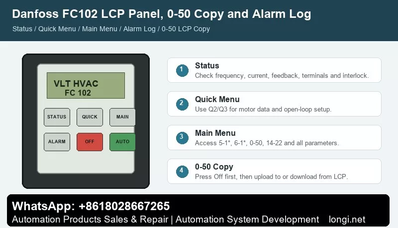
The graphical LCP gives quick access to Status, Quick Menu, Main Menu and Alarm Log. Status is used to confirm command source, reference, feedback, output frequency, current and terminal state. Quick Menu is suitable for motor data and basic open-loop setup. Main Menu is needed for terminal functions, analog scaling, interlock behavior and HVAC application functions.
Before resetting an FC102 alarm, open Alarm Log and record the alarm number with the operating values. On a pump trip, current and feedback at the moment of trip are often more important than the alarm text. If a dry pump or no-flow alarm appears, resetting without checking the process can damage the pump.
0-50 LCP Copy for Replacement Drives
Use 0-50 LCP Copy to back up the drive before replacing a control board or complete drive. Press Off first, upload all parameters to the LCP, then download to the replacement drive if the rating and software are compatible. If the replacement is a different size, copy only compatible data and manually verify motor current, pump/fan limits, relay outputs, PID settings, fire mode and fieldbus parameters.
For service records, photograph the motor nameplate, terminal strip, BMS wiring and active setup number. Many FC102 panels use multiple setups for local service and automatic BMS operation, so copying only one setup can leave the machine half restored.
Terminal 18 Start and Terminal 27 External Interlock
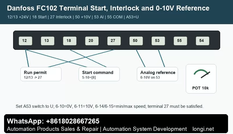
A practical open-loop terminal arrangement is: terminal 12 or 13 provides +24 V, terminal 20 is digital common, terminal 18 is set by 5-10 as Start, and terminal 27 is set by 5-12 as coast stop inverse logic or external interlock. If terminal 27 is configured as a stop/interlock input and is not supplied with +24 V, the drive may show coast, external interlock or remote stop even though terminal 18 is active.
Do not bypass terminal 27 permanently without understanding the safety chain. In HVAC cabinets it may include fire damper contact, pressure switch, freeze protection, motor thermal contact, water flow switch or emergency stop relay. For diagnosis, temporarily prove the input with a safe test jumper, then restore the real interlock wiring.
Terminal 53 Potentiometer or BMS Reference
Terminal 50 supplies +10 V, terminal 53 is a voltage analog input, and terminal 55 is analog common. For a service potentiometer, wire 50 to one end, 55 to the other end and the wiper to 53. Set the reference source to analog input 53, set 6-10 to 0 V, 6-11 to 10 V, 6-14 to the low reference and 6-15 to the high reference.
If the same input is used by the BMS, confirm whether it is 0-10 V or 4-20 mA and whether the A53 switch is set correctly. A voltage/current mismatch can create a stable-looking signal that still produces the wrong speed.
HVAC Faults and Correct Actions
Alarm 2 live zero: analog signal is missing or below threshold. Check terminal 53/54 wiring, common terminal and scaling.
Alarm 7 overvoltage: fan or pump inertia is regenerating energy during deceleration. Increase ramp time or check braking arrangement.
Alarm 8 undervoltage / Alarm 4 phase loss: inspect supply, contactor, fuses and building power dips.
Alarm 60 external interlock: trace the terminal 27 safety chain before replacing the drive.
Alarm 92 no flow, 93 dry pump, 94 end of curve, 95 broken belt: treat these as process faults. Check sensor feedback, valve position, belt condition, pump priming and PID settings.
Alarm 30/31/32 motor phase missing: inspect output contactor, motor cable and winding continuity.
For refrigeration and pump applications, compare the FC202 manual guide.
Final Service Note
The revised article is intentionally more specific than the previous version. It gives a technician a model-aware procedure instead of a repeated manual summary, and it adds internal context that should make the page more useful for search engines and real users.
Danfoss FC51 Practical Manual Guide for Service Engineers: LCP Copy, Password Access, Terminal Control and Analog Speed Reference
Why This FC51 Guide Was Rewritten
The FC51 is a small drive, but it is often installed on machines where downtime is expensive: auxiliary conveyors, dosing screws, small pumps, cooling fans, textile units and compact retrofit panels. A generic parameter summary is not enough for this model because the same symptom can come from several different sources. A terminal start failure may be caused by Auto On not being active, by terminal 27 being used as a stop input, by a missing common on terminal 20, or by a reference source that still points to the keypad.
This rewritten guide treats the FC51 manual as a service workflow. It separates local panel operation, parameter copy, password access, external forward/reverse control, 0-10V speed reference and fault code analysis. The goal is to help a technician restore a machine without guessing or replacing the drive unnecessarily.
LCP 11 and LCP 12: What to Check Before Editing Parameters
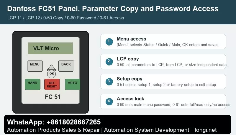
The FC51 normally uses LCP 11 without a potentiometer or LCP 12 with a built-in potentiometer. Both panels give access to Status Menu, Quick Menu and Main Menu. Status Menu is the first place to look because it shows whether the drive is actually receiving a run command and whether the reference value is zero. Quick Menu is useful for motor nameplate data and basic ramps. Main Menu is required for digital input, analog input, password and copy parameters.
Hand On, Off/Reset and Auto On must be understood before terminal control is tested. Hand On runs the drive from the keypad. Off/Reset stops and resets. Auto On allows terminal or serial control. If a technician tries to start from terminal 18 while the drive is left in local mode, the wiring may look wrong even when it is correct.
On LCP 12, the panel potentiometer is not the same as an external potentiometer wired to terminal 53. During troubleshooting, write down whether speed reference is coming from keypad, LCP potentiometer, terminal 53, preset reference or communication.
Parameter Copy: 0-50 LCP Copy and 0-51 Setup Copy
Parameter 0-50 LCP Copy is used to move settings through the removable LCP. Use All to LCP on the source drive, then All from LCP on a target drive with the same rating and hardware. If the target drive is a different size, use the size-independent option and then manually confirm motor current, overload protection, current limit, braking and analog scaling.
Parameter 0-51 Setup Copy is different. It copies setup data inside the same drive. This is useful when the machine has two operating recipes, for example manual jog and automatic production. A good practice is to finish setup 1, copy it to setup 2, and change only the reference source or ramp values that are different.
Do not copy while the machine is running. Stop the drive, wait until the motor has coasted down, and keep a written record of motor data, terminal assignments, reference source and fault action before replacing hardware.
Password Access and Unlocking Without Losing the Machine Setup
Use 0-60 Main Menu Password and 0-61 Access to Main Menu without Password to control who can change parameters. Use 0-65 Quick Menu Password when operators should view status but not change commissioning data. In a service panel, operators normally need status, start/stop and reset; they do not need to edit motor current, terminal logic or analog scaling.
If the FC51 is locked, do not initialize it immediately. First ask for the commissioning password, check the machine documentation, photograph visible parameter screens and save the LCP copy if possible. Initialization is the last step because it can erase the real application logic.
External Forward/Reverse Wiring
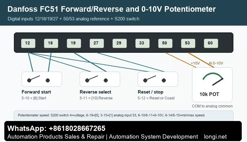
The common terminal logic is simple but easy to miswire. Terminal 12/13 provides the control supply, terminal 20 is the common terminal, terminal 18 is commonly used for start, terminal 27 is often used for coast stop or another digital function, and terminal 29 or 33 may be assigned to jog, reverse or preset reference depending on the application.
For a two-wire forward/reverse selector, use one input as the run command and a second input as reverse direction. For a three-wire station, separate start, stop and direction. Always test terminal state on the LCP before connecting the motor to the machine. If the drive shows a run command but output frequency remains zero, check reference source and minimum reference before changing the power circuit.
External 0-10V Potentiometer Reference
For a standard external potentiometer, wire one end to terminal 50 (+10 V), the other end to terminal 55 (analog common), and the wiper to terminal 53. Then set the reference source to analog input 53. Low voltage should correspond to the minimum reference and high voltage should correspond to the maximum speed required by the machine.
If the drive reports live zero, the analog signal is below the configured threshold. Check whether terminal 53 is set as voltage input, whether the common wire is actually connected to 55, whether shield grounding is creating noise, and whether the potentiometer value is appropriate. A stable 0-10 V measurement at the terminal is more useful than changing random parameters.
Fault Codes That Matter Most on FC51
Live zero / wire break: terminal 53 is below the expected signal. Measure voltage between 53 and 55.
Overvoltage: deceleration is too short, load inertia is high, or braking is not working. Increase deceleration time before replacing hardware.
Undervoltage or phase loss: check supply voltage, input contactor and fuses.
Overcurrent or short circuit: disconnect the motor and test insulation between U/V/W and earth.
Motor overload: verify motor nameplate data and cooling condition.
LCP copy failure: check LCP seating, drive rating, software compatibility and whether the motor is stopped.
The revised article is intentionally more specific than the previous version. It gives a technician a model-aware procedure instead of a repeated manual summary, and it adds internal context that should make the page more useful for search engines and real users.
The Danfoss VLT2900 is an older but still widely used compact AC drive. It appears in fans, pumps, conveyors, textile machines, packaging equipment, dyeing machines and many other small-power industrial systems. Its parameter structure is close to the VLT2800 family, so many operation, wiring and fault-diagnosis methods are shared. For service work, the key is not to read the whole manual line by line, but to quickly master the practical workflow: use the panel correctly, copy parameters, unlock data changes, wire forward/reverse terminals, use a 0-10V potentiometer as a speed reference, and interpret Err.xx fault codes.
This guide summarizes the user manual from a repair and commissioning perspective. Parameter numbers are based on the VLT2900/VLT2800 manual structure. Before commissioning, always verify the nameplate, motor data, control logic and machine safety circuit.
Control Panel and Menu Access
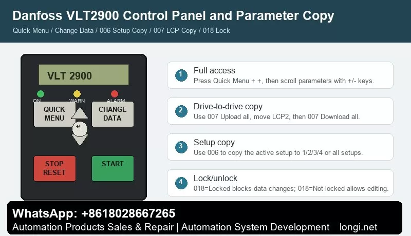
The basic VLT2900 panel normally includes QUICK MENU, CHANGE DATA, +, -, STOP/RESET and START. With an LCP2 control panel, extra keys such as OK, arrow keys, HAND, OFF, AUTO, FWD/REV and JOG may be available. The indicator LEDs show ON, WARNING and ALARM. A warning means an abnormal condition is present but the drive may continue to run; an alarm usually requires fault correction and reset.
QUICK MENU opens the quick commissioning menu. It normally contains motor nameplate data, minimum and maximum reference, ramp times and basic operation settings. Use + / – to scroll, press CHANGE DATA to edit, change the value with + / –, and confirm with CHANGE DATA or OK. Parameter values are stored automatically and remain after power loss.
If only a limited number of parameters are visible, the drive is usually not "encrypted". It is often still in Quick Menu mode. To access all parameters, press QUICK MENU and + at the same time to enter the full menu mode, then scroll to the required parameter.
STOP/RESET stops the drive command and resets alarms, but it is not a safety isolator. For short circuit, earth fault, overtemperature or power-stage faults, disconnect mains power and wait for the DC bus to discharge before touching the terminals.
Parameter Copying: 006 and 007 Are Different
Two parameters are commonly confused: 006 Setup copying and 007 LCP copy.
Parameter 006 Setup copying copies the active setup inside the same drive. It can copy the active setup to Setup 1, 2, 3, 4 or all setups. It is useful when several machine recipes are needed. Stop the motor before copying because changes copied to the active setup can affect drive operation immediately.
Parameter 007 LCP copy is used with the LCP2 panel to move parameters from one drive to another. The normal workflow is:
Install the LCP2 on the source drive.
Enter 007 LCP copy.
Select Upload all parameters.
Move the LCP2 to the target drive.
Select Download all parameters.
If the target drive has a different power size, use Download size-independent parameters instead.
Do not blindly download all parameters between drives of different voltage class, power size or hardware version. After copying, verify motor parameters 102-106, references 204/205, ramps 207/208, terminal parameters in group 300 and communication parameters in group 500.
Locking, Unlocking and "Password" Misunderstanding
VLT2900 does not normally use a password-style lock for routine parameter access. Two conditions are often mistaken for encryption.
The first is limited menu access. Press QUICK MENU + + to enter full menu mode.
The second is the real data-change lock: 018 Data change lock. Set it to Locked [1] to block parameter changes. Set it back to Not locked [0] to allow editing. If the drive shows Warning 99 Locked, check parameter 018. If editing is still impossible, stop the motor, remove active start signals and confirm whether an LCP2 panel is required for editing.
External Forward/Reverse Control by Terminals
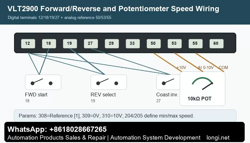
The manual gives practical examples for digital input control. Typical factory assignments include 302 Digital input terminal 18 = Start, 303 terminal 19 = Reversing, and 304 terminal 27 = Reset and coast inverse.
A practical forward/reverse wiring scheme is:
Terminal 12 provides the digital control supply.
Terminal 18 receives the forward start signal. Wire a switch from 12 to 18 and set 302=Start [7].
Terminal 19 receives the reverse selection signal. Wire a switch from 12 to 19 and set 303=Reversing [10].
Terminal 27 is commonly used for coast stop inverse or reset/coast inverse. It normally needs a valid logic signal through the safety circuit. Set 304=Coasting stop inverted [2] or according to the actual machine requirement.
Also check parameter 200 Output frequency range/direction. If the drive is set for clockwise operation only, the reverse input will not produce reverse rotation. For real forward/reverse operation, select a direction range that allows both directions.
Test first at low frequency and without load. Confirm the output frequency, motor direction and mechanical safety before running the machine under load.
Potentiometer Speed Reference: Terminals 50, 53 and 55
The manual example for Potentiometer reference uses a voltage reference through terminal 53. The required settings are 308 Analog input = Reference [1], 309 Terminal 53 min scaling = 0V, and 310 Terminal 53 max scaling = 10V.
Typical 10k ohm potentiometer wiring:
Terminal 50: +10V supply to one end of the potentiometer.
Terminal 55: analog common to the other end.
Terminal 53: analog voltage input to the wiper.
Recommended parameters:
308 Terminal 53 analog input = Reference [1].
309 Terminal 53 min scaling = 0.0V.
310 Terminal 53 max scaling = 10.0V.
204 Minimum reference defines the minimum speed.
205 Maximum reference defines the maximum speed.
207/208 Ramp-up and ramp-down times should be set to match the mechanical inertia.
If the potentiometer does not work, measure the voltage on terminal 53 first. Then check parameter 308 and verify that the drive is in remote control and not being overridden by local reference, preset speed or serial communication. If Err.02 Live zero error appears, terminal 53 or 60 is below 50% of the configured minimum scaling value.
Fault Codes and Troubleshooting
VLT2900 alarms are displayed as Err.xx. A warning stays active while the condition exists. An alarm flashes until reset. A trip-locked fault requires power removal, fault correction and restart before reset.
Err.02 Live zero error: terminal 53 or 60 signal is below the expected minimum. Check potentiometer wiring, analog common, terminal 53 voltage, parameter 309/315 and sensor supply.
Err.05 Voltage warning high / Err.07 Overvoltage: usually caused by too short deceleration, high inertia, brake resistor faults or high mains voltage. Increase ramp-down time and inspect the brake circuit.
Err.06 Voltage warning low / Err.08 Undervoltage: check mains supply, contactor drop-out, rectifier, precharge circuit and DC bus capacitors.
Err.09 Inverter overload: check mechanical overload, drive sizing, acceleration time and cooling.
Err.10 Motor overloaded: verify motor parameters 102-106, load condition and cooling at low speed.
Err.11 Motor thermistor: check the PTC thermistor and wiring between a digital input and terminal 50, and verify parameter 128.
Err.12 Current limit: output current exceeds parameter 221. Check acceleration time, load, torque demand and mechanical friction.
Err.13 Overcurrent: check motor shaft blockage, motor cable, output short circuit and IGBT module. Do not keep resetting repeatedly.
Err.14 Earth fault: inspect motor insulation, motor cable, water ingress and shield contact. Disconnect power and test insulation.
Err.15 Switch mode fault: internal auxiliary power supply fault, usually a board-level repair issue.
Err.16 Short-circuit: check U/V/W phase-to-phase short circuit, motor winding and power module.
Err.17 Serial communication timeout: check group 500 communication parameters, address, baud rate, protocol and cable shielding.
Err.18 HPFB bus timeout / Err.34 HPFB communication fault: fieldbus or PROFIBUS option communication problem.
Err.33 Out of frequency range: check parameter 200, frequency limits and direction restrictions.
Err.35 Inrush fault: inspect precharge resistor, relay, rectifier and DC bus capacitors.
Err.36 Overtemperature: check fan, heatsink dust, ambient temperature, motor cable length, carrier frequency and mains voltage.
Err.37-45 Internal fault: internal control card, EEPROM, RAM, calibration, power card, software or I/O fault. Record the exact code before repair.
Err.50-56 AMT faults: automatic motor adaptation failed. Check motor nameplate data, output cable, motor phase connection and load condition.
Warning 99 Locked: parameter changes are locked. Check 018 Data change lock.
Practical Commissioning Sequence
Start by checking power wiring, motor insulation, earthing and control terminals. Enter full menu access, set motor data 102-106, configure terminal 18/19/27 logic, set reference limits 204/205, set ramps 207/208, configure terminal 53 with 308/309/310, then test the motor at low speed without load. After successful testing, back up parameters. Use 007 LCP copy for drive-to-drive copying and 006 Setup copying for internal setup duplication.
Conclusion
The VLT2900 manual becomes much easier to use when its main structure is clear: QUICK MENU is for fast commissioning, QUICK MENU + + gives full parameter access, CHANGE DATA edits values, STOP/RESET stops and resets, 006 copies internal setups, 007 copies parameters through LCP2, 018 locks or unlocks data changes, 302/303/304 define terminal 18/19/27 control, 308/309/310 define the 0-10V potentiometer reference, and Err.xx codes point the troubleshooting direction.
Used this way, the manual is not just a parameter list. It becomes a practical diagnostic map for commissioning, service and repair of Danfoss VLT2900 drives.
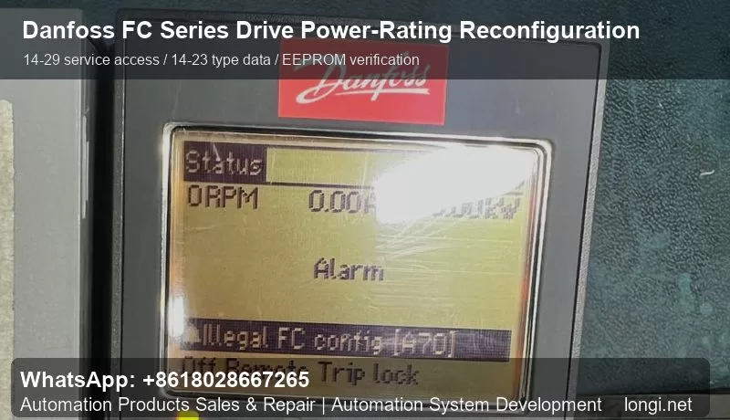
Danfoss VLT FC series drives, including FC102, FC202 and FC302, are frequently seen in industrial repair work. These drives rely on a consistent relationship between the control board, LCP keypad, power board, rectifier/inverter section and the type data stored in memory. After replacing a control board or using a spare board from another drive of the same platform, the drive may power up but report configuration alarms, illegal FC configuration, A70-related messages, or a mismatch between the displayed power rating and the actual power hardware.
The “power-rating change” discussed here is not a method to turn a small drive into a larger drive by software. It is a service operation used to make the stored type data match the real hardware. The repair engineer must verify the nameplate, voltage class, power board, IGBT module, rectifier, DC bus capacitors, heatsink and fan structure before changing the parameters. If the rating is written incorrectly, the drive may appear normal at no load but fail under load due to current, thermal or protection mismatch.
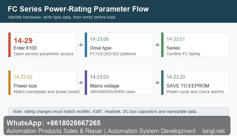
The key service path is usually entered from the LCP. After the keypad displays normally, enter the main menu, find parameter 14-29, press OK, input service code 6100, and confirm. Then enter the 14-23 parameter group. The typical sequence is to set the drive type in 14-23.00, confirm the FC series in 14-23.01, select the correct power size in 14-23.02, select the correct mains voltage class in 14-23.03, and finally use 14-23.20 SAVE TO EEPROM to store the type data permanently.
Saving to EEPROM is important because these parameters are not ordinary application settings. They are involved in drive identification, rated current limits, voltage class recognition, fan behavior, thermal protection and internal protection thresholds. If the EEPROM save step is skipped, the drive may return to the previous configuration after power cycling. For a proper repair, the drive should be powered off, restarted, checked for alarms, and the 14-23 parameters should be reviewed again.
Before any loaded test, start with a no-load power-up. Check DC bus behavior, fan operation, keypad status, alarm history and temperature feedback. Then run the motor without load and verify output current, output voltage, frequency response and motor direction. After that, apply load gradually. If the current reading is obviously too high or too low, inspect the current sensor, power board type, sampling circuit and selected rating. On FC302 applications, an incorrect current scale can also affect vector control performance.
Common mistakes include selecting a higher rating than the actual hardware, ignoring the voltage class, replacing boards only by appearance, clearing alarms without reading the alarm history, and failing to document the original parameters. A reliable repair should include photos of the nameplate, board codes and original settings before modification.
In summary, Danfoss FC series power-rating reconfiguration is a practical repair procedure after board replacement or type-data loss. The core steps are 14-29 with code 6100, type settings in 14-23.00 to 14-23.03, and EEPROM saving through 14-23.20. The most important principle is simple: the parameter data must follow the hardware, not the other way around. When hardware identification, parameter writing, EEPROM storage, power-cycle verification and load testing are all completed, this procedure can restore a repaired FC series drive to a stable and serviceable state.
In an ultramicrotome, the stereomicroscope holder is not merely an accessory for visual observation. It is an important part of the operator interface that affects how easily the user can monitor the specimen block, knife edge, water boat, floating sections, and ribbon formation during cutting.
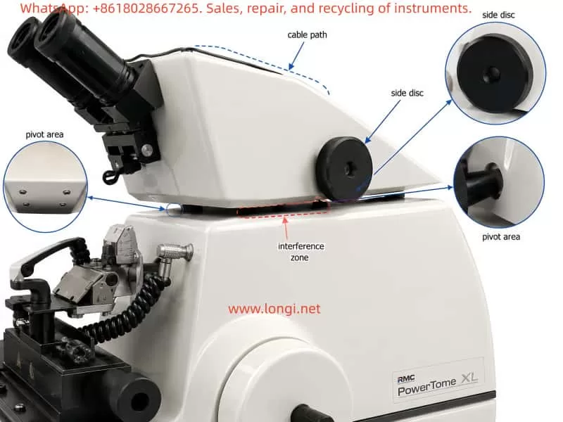
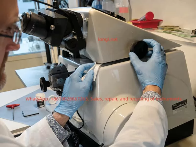
On systems such as the RMC PowerTome XL, the stereomicroscope is mounted on an adjustable support assembly that can be moved laterally or rotated to provide a suitable viewing angle. Under normal conditions, this holder should move smoothly across its working range while still maintaining enough friction to remain stable in the selected position.
A common problem on older ultramicrotomes is that the stereomicroscope holder becomes stiff, uneven, or difficult to move. In some cases, the holder may rotate freely on both sides but become noticeably resistant only when it approaches the central position, approximately parallel to the main longitudinal axis of the instrument.
This type of symptom is important because it does not always indicate a simple lack of lubrication in the vertical pivot. When resistance appears only at one particular angle, the cause is often related to local mechanical interference, internal cable tension, misalignment, or a binding linkage rather than a uniformly dry rotation shaft.
This article explains the mechanical logic behind this fault, describes likely causes, and provides a structured troubleshooting and maintenance approach for stereomicroscope holder rotation problems on ultramicrotomes.
1. Function of the Stereomicroscope Holder
During ultrathin sectioning, the operator must accurately observe the relationship between the specimen block and the knife edge. The stereomicroscope is used to inspect:
Specimen trimming progress
Knife edge position
Clearance angle
Water boat condition
Floating section ribbons
Section compression
Knife contamination
Section collection area
For this reason, the stereomicroscope holder must allow comfortable positioning without excessive force. At the same time, the holder must remain stable once the desired observation angle has been selected.
A properly functioning holder should have the following characteristics:
Smooth movement over the full rotation range
Light but controlled friction
No sudden increase in resistance
No metal-to-metal rubbing noise
No cable pulling or twisting
No visible movement of the microscope when the holder is stationary
Stable positioning without drifting or swinging back
The ideal mechanical condition is not “completely loose.” A well-designed holder usually has a small amount of intentional friction or damping so that the microscope remains where the operator places it.
2. Common Mechanical Designs Used in Microscope Holders
The mechanical design of microscope holders varies between manufacturers and instrument generations. However, most designs fall into several general categories.
2.1 Single Vertical Pivot Design
The simplest design uses a central vertical shaft mounted in a bushing or bearing. The microscope support rotates around this vertical axis.
The assembly may include:
Vertical steel shaft
Bronze or polymer bushing
Thrust washer
Friction disc
Spring washer
Adjustment screw
Locking screw
Retaining collar
In this type of system, dried grease or excessive preload usually causes resistance across the entire rotation range.
2.2 Dual-Side Support or Synchronized Adjustment Design
Some ultramicrotomes use a more complex holder structure with two external side discs, knurled wheels, or adjustment knobs. These may be connected internally through a shaft, linkage, cam system, or friction mechanism.
The visible black discs may not be simple locking knobs. They may be part of a synchronized lateral viewing system or a mechanical support structure for the stereomicroscope holder.
Possible internal components include:
Connecting shafts
Cam followers
Friction discs
Eccentric mechanisms
Linkage rods
Gear segments
Retaining collars
Compression springs
Position stops
In such systems, a problem that occurs only at one angle may be caused by internal binding rather than a dry central axis.
2.3 Combined Sliding and Rotating Support Systems
Some holders include both lateral travel and rotational movement. These may use guide rails, sliding blocks, pivot joints, or adjustable friction pads.
Over time, hardened grease, dust accumulation, corrosion, or mechanical misalignment may cause uneven movement.
2.4 Holder Assemblies with Internal Wiring
Modern stereomicroscope holders may contain or guide several cables, including:
Microscope illumination wires
Camera cables
LED power cables
Video output cables
Fiber-optic light guides
Sensor wiring
Internal control harnesses
These cables move with the holder. If they are routed incorrectly, trapped inside the support, or too tight, they can create resistance at a specific point in the rotation travel.
3. Why Localized Resistance Is an Important Clue
One of the most useful diagnostic details is whether the resistance is uniform or localized.
If the holder feels stiff through the entire movement range, likely causes include:
Dried grease
Corroded pivot shaft
Tight friction adjustment
Overloaded spring washer
Worn bushing
Excessive mechanical preload
Contaminated thrust surface
However, if the holder moves relatively freely on both sides and becomes difficult only near the central position, the diagnosis changes.
Localized resistance usually suggests one of the following:
A cable is being stretched or compressed
A mechanical stop is contacting too early
A linkage is binding at its center position
A cam or friction plate is misaligned
A support component is touching the instrument housing
An internal wire harness is trapped
A retaining collar is offset
The holder assembly is slightly distorted
A side adjustment mechanism is becoming tight at a specific geometry
This distinction is critical. Adding oil to a pivot will not solve a cable-routing problem, a misaligned cam, or a mechanical interference issue.
4. Typical Failure Modes
4.1 Hardened or Aged Lubricant
Lubricants gradually age. Grease may become thick, dry, sticky, or contaminated by dust. In humid or coastal environments, corrosion can also accelerate degradation.
Typical symptoms include:
Stiff movement across the full rotation range
Rough or dry feeling during movement
Resistance increasing in cold conditions
Slight improvement after repeated movement
Uniform friction in both directions
The correct repair normally involves disassembly, removal of old grease, cleaning of the shaft and bushing, inspection for damage, and application of a thin layer of suitable precision lubricant.
4.2 Excessive Friction Adjustment
Many support systems include a friction adjustment mechanism to prevent the microscope from moving unintentionally.
If this adjustment becomes too tight, the holder may become difficult to rotate. Causes include:
Adjustment screw tightened too much
Spring washer compressed excessively
Friction pad swollen or distorted
Incorrect reassembly after previous service
Retaining collar moved from its original position
In some systems, the friction is not perfectly uniform. A cam, offset washer, or eccentric component may cause higher resistance near one position.
4.3 Internal Cable Tension
Internal cable tension is one of the most overlooked causes of localized resistance.
A cable may be pulled tight when the holder reaches a certain angle. The cable may then act like a spring, pulling the holder back or creating a noticeable resistance zone.
Signs of cable-related resistance include:
Holder moves freely on one side but tightens near the center
Resistance changes if cables are moved by hand
Visible cable stretching or twisting
Resistance stronger in one direction than the other
No obvious grinding sound
Holder tends to return slightly after release
Cable problems may occur because of:
Incorrect cable routing
Lost cable clamp
Cable tie installed too tightly
Aged stiff cable insulation
Excessive cable shortening during previous repair
Internal harness trapped between moving parts
4.4 Mechanical Interference with the Housing
If the holder or support structure has shifted slightly, it may contact the main instrument housing at a particular angle.
This may be caused by:
Instrument impact during transport
Loose mounting screws
Deformed sheet-metal cover
Bent support bracket
Misaligned bearing housing
Previous incorrect assembly
Wear in the pivot bushing
Visible clues may include:
Paint scratches
Bright metal rubbing marks
Plastic dust
Black powder from friction surfaces
Uneven gaps between the holder and instrument body
Contact marks near the pivot region
4.5 Binding in a Dual-Side Adjustment Mechanism
When a holder has large side discs or synchronized wheels, the mechanism may include a complex internal transmission system.
Potential faults include:
Dry cam surface
Misaligned synchronizing shaft
Loose retaining screw
Damaged friction disc
Uneven spring tension
Bent internal linkage
Worn or cracked plastic bushing
Binding gear segment
Offset eccentric mechanism
This type of problem often produces localized resistance because the mechanical geometry changes during rotation.
5. Why Oil Should Not Be Applied Immediately
It is tempting to apply oil directly into a visible gap around the rotation axis. However, this is not recommended until the fault source has been confirmed.
Several risks exist.
5.1 Oil Can Enter Sensitive Areas
Low-viscosity oil may migrate into:
Microscope optics
Knife area
Sample stage
Internal electronic components
Friction pads
Cable channels
Instrument housing
Once oil migrates, it can collect dust and create sticky deposits.
5.2 Penetrating Sprays Can Remove Original Grease
Products such as general-purpose penetrating sprays may temporarily reduce friction, but they can also dissolve or displace the original grease. This may leave internal components poorly protected after the solvent evaporates.
5.3 Excess Lubricant Can Create New Problems
Too much grease or oil can:
Attract dust
Increase contamination risk
Spread into the cutting area
Affect friction adjustment
Cause the holder to become too loose
Stain laboratory surfaces or specimens
5.4 Lubrication Will Not Fix Mechanical Interference
If the real problem is a trapped cable, a rubbing housing, or a binding linkage, oil will not solve it. It may only hide the issue temporarily.
6. Recommended Inspection Procedure
Before considering disassembly, the following inspection procedure should be followed.
Step 1: Make the Instrument Safe
Before handling the holder:
Switch off the instrument
Disconnect power if necessary
Remove the knife or move it to a safe position
Remove the specimen block if possible
Protect the cutting area
Ensure the holder cannot swing into the knife assembly
Ultramicrotome knives are extremely sharp. Even minor movement of the microscope holder can create an accident risk if the knife is exposed.
Step 2: Identify the Exact Tight Position
Move the holder slowly through its full travel and record:
Where the resistance begins
Whether the resistance is repeatable
Whether it is stronger when moving left-to-right or right-to-left
Whether the holder stops suddenly or gradually
Whether any rubbing sound is present
Whether the holder moves more easily when lifted slightly
If the resistance always occurs at the same position, this strongly indicates a geometry-related issue rather than random lubrication failure.
Step 3: Inspect Cables and Wiring
Carefully check:
Microscope rear cables
Illumination cables
Fiber-optic light guides
Camera wiring
Cable loops behind the holder
Cable routing under the support
Wiring near the side adjustment discs
Any wires entering the main housing
At the tight position, inspect whether any cable becomes:
Straightened
Twisted
Compressed
Pulled against a sharp edge
Pinched between moving parts
Tensioned around the pivot
A cable may be hidden inside the support housing, so visible external wiring should not be assumed to be the only source.
Step 4: Check for Contact Marks
Inspect the holder and surrounding housing for:
Scratched paint
Polished metal contact areas
Plastic rubbing marks
Wear debris
Uneven clearances
Deformed covers
Loose panels
Mechanical interference often leaves visible evidence.
Step 5: Test the Side Adjustment Discs
If two large side discs or knurled wheels are present, compare their behavior at different holder positions.
Check:
Are both discs equally easy to turn?
Do they become tight when the holder reaches the difficult central position?
Does turning one disc affect the other?
Is there any slipping, clicking, or irregular motion?
Does one disc have significantly more resistance than the other?
If the discs also become stiff near the same position, the problem is likely inside the synchronized adjustment mechanism.
If the discs remain smooth but the holder itself becomes difficult to swing, the problem is more likely related to the main pivot, cable routing, or housing interference.
7. Components That Should Not Be Removed First
Without a detailed service manual or exploded drawing, several components should not be removed casually.
These include:
Large black knurled side discs
Center screws inside the side discs
Retaining screws supporting the holder assembly
Bottom screws that may hold the entire support structure
Screws near internal spring or friction mechanisms
Any screw that appears to retain a shaft
Removing these parts may cause:
Misalignment of the microscope holder
Loss of synchronization between both sides
Release of springs or friction washers
Shift of the rotation center
Loss of stable positioning
Difficulty restoring original adjustment
Damage to internal cable routing
Before removing any screw, the support structure should be properly supported and photographs should be taken from multiple angles.
8. Proper Lubrication Method
If inspection confirms that the pivot shaft or bushing is genuinely dry or contaminated, lubrication should be performed correctly.
The goal is not to flood the mechanism with oil. The goal is to restore a thin, stable lubricating film.
A suitable lubricant should have:
Low evaporation rate
Good metal compatibility
Good plastic compatibility
Stable behavior over time
Low migration tendency
Appropriate viscosity
Resistance to humidity and oxidation
Suitable choices may include precision synthetic grease or PTFE-compatible instrument grease, depending on the materials involved.
A typical lubrication procedure includes:
Remove the holder assembly carefully.
Photograph all components before disassembly.
Clean old grease from the shaft, bushing, thrust washers, and friction surfaces.
Inspect for corrosion, scoring, burrs, cracks, or uneven wear.
Apply a very thin layer of suitable grease.
Reassemble in the original order.
Adjust preload gradually.
Test movement across the full rotation range.
Confirm that the holder remains stable but not excessively tight.
Excess lubricant should always be removed. The mechanism should not have visible grease squeezing out around the pivot.
9. When Professional Service Is Recommended
Professional service should be considered when any of the following conditions are present:
The holder binds strongly at one position
The holder produces metal scraping sounds
The side adjustment discs are not synchronized
The holder has vertical play or wobble
The holder suddenly releases after resistance
Internal cables appear to be trapped
The support structure touches the instrument housing
The holder is difficult to reassemble after partial disassembly
The instrument has high-value optical or cutting accessories
The mechanism includes hidden springs, cams, or friction components
Although the fault may appear minor, incorrect disassembly can affect the microscope position, viewing geometry, cable routing, and long-term usability of the ultramicrotome.
10. Conclusion
A stiff stereomicroscope holder on an ultramicrotome should not automatically be treated as a lubrication problem.
When the holder is difficult to move only near the central position, the most likely causes are localized mechanical interference, cable tension, internal linkage binding, misalignment, or non-uniform friction adjustment.
The correct diagnostic approach is:
Identify whether resistance is uniform or localized.
Inspect cables and external contact points.
Check for housing interference and wear marks.
Compare the behavior of side adjustment mechanisms.
Avoid unnecessary disassembly.
Lubricate only after confirming that the pivot or bushing is the true source of the problem.
A careful inspection sequence can prevent unnecessary damage and reduce the risk of contaminating a precision ultramicrotome with unsuitable lubricants. Proper diagnosis is more important than immediately applying oil, especially when the symptom is angle-dependent rather than constant.
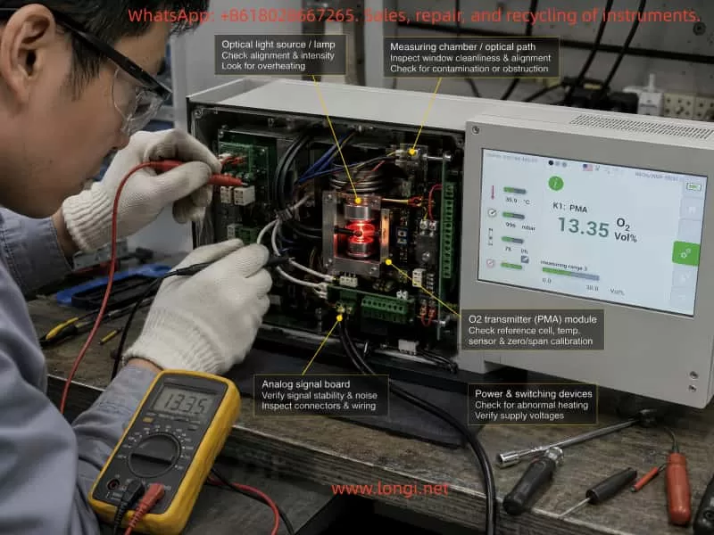
Online oxygen analyzers are widely used in flue gas monitoring, industrial furnaces, inert-gas protection systems, chemical processes, combustion control, gas blending, environmental monitoring, and laboratory applications. Compared with portable oxygen meters, an online analyzer is usually a multi-module system consisting of a sample gas path, flow-control section, measuring chamber, optical source or sensing element, signal-conditioning circuit, analog acquisition module, display controller, alarm circuit, and 4–20 mA output stage.
When an analyzer begins to show incorrect oxygen concentration, users often suspect sensor aging, chamber contamination, or calibration drift. In many cases, operators attempt to correct the issue by adjusting zero, span, or internal parameters. However, for analyzers incorporating an optical source, measuring chamber, optical receiver, analog conditioning circuitry, and signal-acquisition electronics, calibration alone may only temporarily correct the displayed value. It may not resolve deeper problems such as optical reference drift, excessive optical-source heating, optical-path misalignment, or unstable analog acquisition.
This article examines a representative troubleshooting case involving an online oxygen analyzer with abnormal oxygen readings, an overheating optical lamp assembly, intermittent analog signal loss, and a condition in which the displayed oxygen value could be adjusted close to 20.99% O₂ by changing the lamp position. The purpose is to provide a systematic diagnostic framework for third-party maintenance engineers and technical personnel.
1. A Displayed Oxygen Value Does Not Prove That the Measurement System Is Healthy
One of the most common misunderstandings in analyzer troubleshooting is assuming that the instrument is functioning normally simply because it powers on, displays an oxygen value, and has a normal sample flow.
In reality, the displayed oxygen concentration is the final result of a multi-stage measurement chain. If any part of that chain drifts, weakens, becomes contaminated, or loses electrical stability, the analyzer may still display a seemingly reasonable value even though the actual oxygen measurement is incorrect.
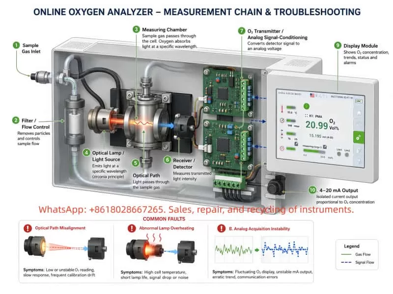
A typical measurement chain can be summarized as follows:
Sample Gas
   ↓
Sampling Line and Filter System
   ↓
Flow Control and Pressure Stabilization
   ↓
Measuring Chamber
   ↓
Optical Source / Sensing Element / Receiver
   ↓
Analog Signal Conditioning
   ↓
A/D Conversion and Controller Processing
   ↓
Display, Alarm, and 4–20 mA Output
Any fault within this chain can create measurement errors. Typical examples include:
Air leakage into the sample gas line;
Plugged filters reducing actual sample flow;
Moisture or condensate entering the chamber;
Oil mist or dust contamination on optical windows;
Therefore, an engineer should never evaluate an oxygen analyzer only by looking at the final number on the display. The correct question is:
How is that number being generated, and are all physical and electrical stages producing valid information?
2. Persistent Low or High Oxygen Readings Should Not Immediately Be Attributed to Chamber Contamination
Measuring-chamber contamination is indeed one of the most common causes of online analyzer errors. In flue gas, chemical off-gas, oil mist, dusty gas streams, humid gas, or corrosive process environments, the internal gas path can become contaminated by:
Fine dust deposits;
Condensed moisture;
Oil film;
Hydrocarbon residue;
Acidic compounds;
Salt crystals;
Optical-window contamination;
Internal flow-path deposits;
Restricted flow channels;
Filter blockage.
These conditions can cause slow response, zero drift, span deviation, poor repeatability, nonlinear response, or unstable oxygen readings.
However, chamber contamination should not become the default explanation for every oxygen-measurement problem.
If the analyzer also shows any of the following conditions, the problem is likely more complex than simple chamber contamination:
The optical lamp or glass source becomes abnormally hot;
Lamp brightness appears unusually strong or unstable;
A power transistor or switching device overheats severely;
Analog output cannot be read intermittently;
Internal analog acquisition becomes unavailable;
Disconnecting a cable causes the display to fall to zero;
Reconnecting a cable restores the reading but with offset;
Moving the lamp position significantly changes the oxygen reading;
Mechanical adjustment of lamp distance can force the display close to 20.99% O₂.
These symptoms indicate that the fault may involve the optical measurement system, lamp-driving circuit, analog conditioning stage, or A/D acquisition path.
3. The Optical Source Is a Measurement Reference, Not Merely a Lamp
In analyzers using an optical source, optical chamber, receiver, and signal-processing circuit, the lamp is not simply an illumination device. It is part of the measurement reference system.
Depending on the analyzer design, the source may be a miniature lamp, infrared emitter, heated optical element, or special light-emitting component. Regardless of design, its function is to provide stable optical energy to the measurement chamber. The receiver then evaluates light intensity, absorption changes, spectral behavior, or optical-path variation to determine the gas concentration.
For correct operation, the optical source must satisfy several conditions:
Stable light output;
Stable operating position;
Correct optical direction;
Accurate alignment with the receiving area;
Proper electrical drive current;
Controlled operating temperature;
Fixed geometric relationship to the chamber and receiver;
No movement due to vibration, thermal expansion, loose mounting, or previous maintenance work.
Even a small mechanical shift in lamp distance, angle, height, or centering can alter the received optical signal.
For example:
Increasing lamp-to-receiver distance may reduce received light intensity;
Moving the lamp off-axis may reduce effective light transmission;
Changing lamp height may shift the light spot away from the receiver window;
Changing lamp angle may alter reflection and refraction characteristics;
A loose mounting bracket may create unstable readings during vibration.
Therefore, if moving the optical lamp causes a major oxygen-reading change, the lamp position and optical alignment are directly influencing the measurement.
This is an important diagnostic finding, but it does not automatically mean the analyzer is fully repaired.
4. Why Adjusting the Reading to 20.99% O₂ Does Not Automatically Mean the Analyzer Is Fully Repaired
The oxygen concentration in clean ambient air is approximately 20.9%. Therefore, when an analyzer displays around 20.99% O₂ while sampling air, it may appear to have returned to normal operation.
However, from an engineering and measurement perspective, this only proves that:
At the current lamp position, current temperature, current gas flow, and current environmental condition, one measurement point is close to the expected value.
It does not prove that the entire analyzer has been restored to specification.
The following conditions may still be incorrect:
Zero-point accuracy;
Span-point accuracy;
Mid-range linearity;
Lamp alignment relative to design center;
Lamp current and electrical drive condition;
Lamp thermal stability;
Receiver sensitivity;
Analog signal stability;
4–20 mA output accuracy;
Long-term drift behavior;
Temperature influence;
Flow-rate influence;
Pressure influence;
Repeatability after restart.
For example, an analyzer may display 20.99% O₂ in air but still display 1.5% O₂ when exposed to nitrogen or 90% O₂ when exposed to a high-oxygen calibration gas. In such a situation, the air point appears correct while the zero point, span point, or linearity remains defective.
Therefore:
Adjusting the air point to approximately 20.99% O₂ is a positive indication that the optical path can still generate usable signal, but it is not a replacement for complete calibration and stability verification.
5. Diagnostic Significance of Optical Source Heating and Power Transistor Overheating
If the glass lamp, optical source, nearby metal fixture, or lamp-driving transistor becomes noticeably hot, the condition must be evaluated carefully.
Some lamp temperature rise may be normal. However, there is a major difference between normal operating temperature and abnormal overheating.
Normal operating behavior may include:
Gradual warm-up after power-on;
Stable light intensity after warm-up;
Controlled temperature rise;
No continuous brightness increase;
Manageable temperature on the driving device;
No smell of overheating;
No discoloration of wiring or plastic;
Stable oxygen reading;
Stable analog output.
Abnormal overheating may include:
Lamp brightness gradually increasing without stabilization;
Temperature continuing to rise;
Power transistor becoming too hot to touch quickly;
Strong heat around the glass lamp;
Oxygen reading drifting with temperature;
Analog output becoming unstable;
Reading changing significantly when the lamp is moved;
Measurement returning to zero or becoming implausible;
Burnt smell or thermal discoloration;
Output instability after several minutes of operation.
When a power transistor overheats, it may be operating under one or more abnormal conditions:
Excessive lamp current;
Continuous full-duty operation;
Incorrect PWM duty cycle;
Incomplete transistor switching;
Linear-region operation with high power dissipation;
Optical lamp load abnormality;
Current-limiting circuit failure;
Current-sense resistor drift;
Lamp resistance change due to aging;
Drive voltage too high;
Faulty solder joints;
Degraded capacitors or gate-drive components;
Inadequate heatsinking.
For this reason, any analyzer with a visibly overheating lamp and hot switching transistor should not be left powered for long periods during troubleshooting. Continued operation may damage the lamp, power transistor, PCB traces, connectors, wiring insulation, or surrounding plastic components.
6. Avoid Misidentifying the Optical Lamp as a Temperature Sensor
Inside industrial analyzers, many components are black, glass-sealed, mounted under metal clamps, or connected with two wires. Such parts can easily be mistaken for thermistors, temperature probes, thermal cutoffs, optical sensors, or heating elements.
In optical analyzers, however, a glass-bodied component may simply be the optical lamp.
A lamp and a temperature sensor can appear physically similar, but their behavior is different.
Feature
Optical Lamp / Light Source
NTC/PTC Temperature Sensor
Emits visible light when powered
Often yes
Normally no
Generates significant heat
Often yes
Usually minimal
Driven by power transistor
Common
Usually not directly
Affects optical signal directly
Yes
Normally indirect
Reading changes when position is moved
Yes
Usually no
Requires optical alignment
Yes
No
May contain visible filament or glowing area
Often
Normally not
If moving the component changes oxygen readings significantly, it is much more likely to be part of the optical source or optical path than a simple temperature-measurement device.
This distinction is important because an incorrect assumption may send troubleshooting in the wrong direction. A glowing lamp should not be treated as a failed thermistor merely because it becomes hot.
7. Why Analog Signal Acquisition Faults Can Make an Analyzer Look Normal While Remaining Unreliable
Many online oxygen analyzers do not display raw sensor output directly. Instead, the signal passes through several analog and digital stages before appearing on the screen.
A simplified signal path may look like this:
Optical Receiver Signal
   ↓
Pre-Amplifier
   ↓
Filtering and Offset Conditioning
   ↓
Reference Comparison
   ↓
A/D Conversion
   ↓
Microcontroller Calculation
   ↓
Display Value
   ↓
4–20 mA Output
If any stage in this signal chain becomes unstable, the analyzer may display an incorrect value even while the optical system remains functional.
Typical analog-chain problems include:
Operational-amplifier offset drift;
Precision-resistor value change;
Reference-voltage instability;
Connector oxidation;
Broken solder joints;
Weak analog ground;
A/D input-channel fault;
Leaky filter capacitors;
Reduced photodetector output;
Gain change in amplifier stages;
Faulty analog isolator;
Internal 4–20 mA output failure;
Electrical interference entering weak signal lines.
When the analyzer has previously shown symptoms such as “analog signal unreadable,” “output temporarily missing,” “display returns to zero after a connector is removed,” or “reading restores after reconnection,” the following areas should be inspected carefully:
Sensor-to-transmitter connectors;
Signal-conditioning board supply rails;
Analog ground and reference ground;
Optical receiver output;
Amplifier input and output stages;
A/D converter input;
4–20 mA output module;
Connector pins and solder joints;
Cable strain-relief points;
Isolation circuits and internal relays.
Such faults are dangerous because the analyzer may appear normal under one condition but drift again when temperature changes, vibration occurs, power fluctuates, or a connector moves slightly.
8. Optical Path Errors and Analog Acquisition Errors Are Often Coupled
In many analyzers, optical faults and analog signal faults are not independent.
For example, if the lamp moves away from its intended optical position, the receiver receives less light. The analog amplifier may then amplify a weaker signal more aggressively. The display may still show a reasonable oxygen value, but the signal-to-noise ratio becomes poor.
Under these conditions, the analyzer may become sensitive to:
Vibration;
Temperature variation;
Lamp movement;
Power-supply ripple;
Flow-rate changes;
Connector contact resistance;
Electromagnetic interference;
Warm-up time;
Internal mechanical stress.
Typical field behavior may include:
Calibration appears successful but does not remain stable;
Reading changes after warm-up;
Oxygen display fluctuates after vibration;
4–20 mA output differs from displayed value;
Small lamp movement causes large oxygen changes;
A stable reading is only achieved at a very specific lamp position;
Restarting the analyzer temporarily changes performance;
Analog signal becomes weak or unavailable intermittently.
Therefore, adjusting the lamp position alone may produce a correct reading at one point but does not address the underlying electrical stability of the analog measurement chain.
Likewise, repairing only the analog board without restoring correct lamp alignment may leave the optical measurement reference unstable.
A reliable repair requires both the optical and electronic measurement chains to be restored.
9. Recommended Diagnostic Sequence: Confirm the Physical Measurement Chain Before Adjusting Parameters
For an online oxygen analyzer showing inaccurate readings, the following diagnostic sequence is recommended.
Step 1: Verify Basic Operating Conditions
Check:
Supply voltage stability;
Grounding quality;
Sample flow rate;
Sample pressure;
Gas dryness;
Filter condition;
Condensate presence;
Sampling-line leakage;
Air ingress;
Measuring-chamber contamination.
This step eliminates external gas-path problems.
Step 2: Verify Optical Source Operation
Check:
Whether the lamp turns on correctly;
Whether brightness stabilizes after warm-up;
Whether heating is excessive;
Whether the lamp mount is loose;
Whether lamp position is centered;
Whether lamp distance has changed;
Whether the lamp is tilted;
Whether the glass body is darkened or aged;
Whether lamp leads are oxidized;
Whether the socket or clamp is loose;
Whether supply voltage and lamp current are reasonable.
If moving the lamp slightly causes a large oxygen-reading change, inspect the lamp holder, mounting bracket, alignment guide, retaining clip, positioning slot, and mechanical reference surfaces.
Step 3: Inspect the Optical Path and Measuring Chamber
Check:
Optical-window contamination;
Oil film;
Dust accumulation;
Condensate;
Oxidation on reflective surfaces;
Receiver-window contamination;
Obstruction in the optical path;
Lamp-to-receiver alignment;
Loose internal fasteners;
Incorrect position after previous maintenance.
The purpose of this step is to restore optical transmission efficiency and mechanical alignment.
Step 4: Inspect the Power Driver and Heating Circuit
Check:
Lamp supply voltage;
Lamp operating current;
Switching-transistor temperature;
Heatsink condition;
Transistor leakage or short circuit;
PWM drive waveform if available;
Current-sense resistor value;
Current-limiting components;
Electrolytic capacitor condition;
Gate-drive components;
PCB solder joints;
Supply voltage level.
If the switching transistor becomes extremely hot, do not run the analyzer for long periods until the drive stage has been checked. Continued overheating may damage the lamp and PCB.
Step 5: Inspect Analog Acquisition and Signal Conditioning
Check:
Signal-conditioning board supply rails;
Sensor signal presence;
Amplifier output stability;
Reference voltage;
Analog ground;
Connector integrity;
A/D sampling input;
4–20 mA output consistency;
Signal behavior when lamp position changes;
Signal behavior when connectors are moved.
The objective is to confirm that the physical optical signal is being converted and delivered correctly to the controller.
Step 6: Perform Calibration Only After Hardware Stability Is Confirmed
Once the optical source, optical path, power driver, measuring chamber, and analog acquisition chain are stable, perform zero and span calibration.
Recommended verification points include:
Zero gas point;
Ambient air point;
Span-gas point;
Intermediate concentration point;
Long-term stability;
4–20 mA output accuracy;
Alarm threshold behavior;
Flow-rate sensitivity;
Temperature sensitivity.
Adjusting parameters before restoring the hardware baseline may hide the real fault and make subsequent diagnosis more difficult.
10. Post-Repair Verification Must Include Stability, Not Only Instantaneous Accuracy
After repairing an online oxygen analyzer, the instrument should not be considered acceptable based only on one displayed value.
At minimum, the following verification steps are recommended.
1. Ambient Air Verification
With clean air applied, the analyzer should indicate approximately 20.9% O₂.
However, this is only one verification point.
2. Zero Verification
Apply suitable zero gas and confirm that the low-oxygen reading approaches the expected zero range without excessive residual value.
3. Span Verification
Apply a known oxygen calibration gas to verify span accuracy.
4. Linearity Verification
Use at least two different oxygen concentrations to check whether the analyzer responds proportionally across its intended range.
5. Long-Term Run Test
Operate the analyzer for at least 30 minutes, one hour, or longer while observing:
Lamp temperature;
Power-transistor temperature;
Oxygen drift;
Analog-output stability;
Flow stability;
Alarm behavior;
Signal dropouts;
Restart repeatability.
6. Analog Output Verification
Confirm that displayed oxygen value and 4–20 mA output correspond correctly. Verify the output at:
Zero oxygen point;
Ambient-air point;
Full-scale point;
Intermediate concentration point.
Only after all of these conditions are satisfied can the analyzer be considered stable for long-term operation.
11. Conclusion: Oxygen Measurement Errors Are Often System-Level Faults Rather Than Single-Component Problems
For online oxygen analyzers containing an optical source, measuring chamber, receiver, and analog signal-acquisition circuitry, inaccurate oxygen readings should not automatically be blamed on chamber contamination or calibration drift.
When the analyzer shows a combination of symptoms such as:
Incorrect oxygen concentration;
Abnormal lamp or glass-source heating;
Severe heating of the power transistor;
Oxygen reading affected by lamp position;
Display returning close to 20.99% after optical adjustment;
Intermittent analog signal loss;
Display changes caused by connector status;
Temporary recovery after parameter calibration;
Risk of drift after warm-up,
the problem should be treated as a combined fault involving the optical measurement chain, lamp-driving system, and analog acquisition electronics.
The correct maintenance philosophy is not merely to adjust parameters or clean the measuring chamber. The analyzer should be examined sequentially through:
Gas path → optical source → optical path → power driver → analog acquisition → output circuit → calibration → stability verification.
Only when the optical source is mechanically stable, lamp heating is controlled, the receiver signal is sufficient, analog acquisition is stable, 4–20 mA output matches the display, zero and span are correct, and long-term drift remains within acceptable limits can the analyzer be considered fully restored for reliable industrial operation.