1. Overview of the Fault
In Schneider Electric Altivar variable frequency drives, braking-related faults are commonly encountered in applications involving rapid deceleration, high-inertia loads, lifting mechanisms, centrifugal machines, conveyors, winding equipment, woodworking machinery, injection molding machines, and other systems with frequent start-stop cycles.
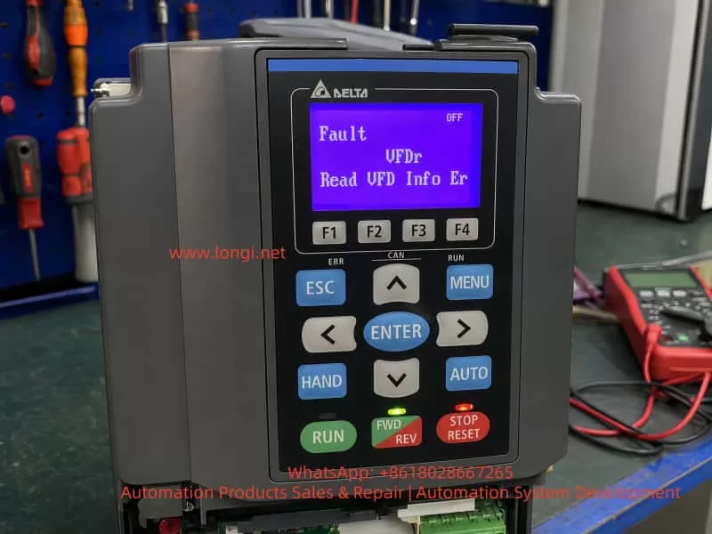
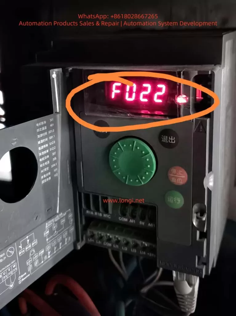
When the display shows a code such as bUF, BUF, BUF0, or a similar braking-circuit-related message, the fault should generally be treated as a braking circuit abnormality. In many cases, it indicates that the drive has detected an abnormal condition in the braking branch, especially a possible short circuit, excessively low resistance, damaged braking transistor, or braking unit drive failure.
This fault should not be interpreted simply as “the braking resistor is defective.” The braking system is made up of several interconnected sections, including the DC bus, braking IGBT, braking resistor, braking wiring, braking parameters, external braking unit, thermal protection, machine inertia, and deceleration settings. A failure in any one of these sections may trigger a braking-related fault.
In practical maintenance work, simply replacing the braking resistor without checking the internal braking transistor may not solve the real problem. Likewise, repeatedly resetting the drive without checking the external circuit may lead to more serious damage to the power module, rectifier bridge, DC bus capacitors, IGBT assembly, driver board, or control board.
Therefore, troubleshooting a bUF / BUF fault should follow a systematic sequence:
- Identify when the fault occurs.
- Isolate the external braking circuit.
- Test the braking resistor and wiring.
- Check the internal braking IGBT or braking module.
- Review the deceleration conditions and braking parameters.
- Confirm the repair through staged running tests.
2. Basic Operating Principle of the Braking System
2.1 Why overvoltage occurs during motor deceleration
During normal motor operation, the variable frequency drive converts incoming AC power into DC voltage through its rectifier section. The inverter stage then converts the DC bus voltage back into adjustable-frequency AC output for the motor.
During acceleration and normal running, electrical energy flows from the drive to the motor.
However, when the motor decelerates quickly, when a heavy load drives the motor, when a hoist lowers a load, when a winding machine releases material, or when a large fan is stopped rapidly, the motor can enter regenerative operation.
In regenerative operation, the motor no longer consumes electrical energy. Instead, it becomes a generator and returns mechanical energy back into the drive’s DC bus.
If this regenerated energy cannot be dissipated, the DC bus voltage rises rapidly. Once the voltage exceeds the drive’s protection threshold, the inverter will trip on a DC bus overvoltage fault.
2.2 Function of the braking resistor
A braking resistor is used to absorb regenerative energy and convert it into heat.
When the DC bus voltage rises above a preset threshold, the drive activates its internal braking IGBT. The braking IGBT switches on and connects the braking resistor to the DC bus.
The regenerative energy is then discharged through the braking resistor and converted into heat.
For this reason, a braking resistor is not an ordinary resistor used only for current limiting. It is a high-power energy absorption component that must be selected according to resistance value, power rating, duty cycle, thermal capacity, and machine operating conditions.
2.3 Main components of a braking circuit
A typical VFD braking system includes:
- DC bus capacitors
- DC bus voltage sensing circuit
- Internal braking IGBT or braking transistor
- Braking IGBT driver circuit
- Braking resistor
- Braking resistor cables
- Braking terminals
- External braking unit, if required
- Thermal protection device
- Deceleration parameters
- Load inertia and regenerative energy conditions
A fault in any of these sections can cause braking-related alarms, DC overvoltage trips, resistor overheating, braking transistor damage, or bUF / BUF type faults.
3. Meaning of bUF / BUF Type Faults
A bUF / BUF type fault generally indicates an abnormal condition in the braking circuit, with particular attention required for possible short circuit conditions, low-resistance conditions, damaged braking IGBT, or abnormal braking drive control.
This type of fault should not be confused with a braking resistor overload fault.
A braking resistor overload fault usually means that the drive’s thermal model has calculated excessive temperature rise in the braking resistor. This is often caused by frequent braking, short deceleration times, insufficient resistor power rating, excessive machine inertia, or incorrect braking parameters.
By contrast, a bUF / BUF fault usually points more directly to a hardware abnormality in the braking branch.
Possible causes include:
- Shorted braking resistor
- Braking resistor resistance too low
- Incorrect braking resistor wiring
- Damaged braking cable insulation
- Braking cable shorted to ground
- Braking terminals connected incorrectly
- Failed internal braking IGBT
- Shorted braking transistor
- Braking driver circuit malfunction
- Failed external braking unit
- Incorrect connection between DC bus terminals and braking terminals
- Moisture, conductive dust, metal particles, or oil contamination around terminals
- Faulty DC bus voltage detection circuit
- Control board misdetection
For this reason, a bUF / BUF fault should first be approached as a braking hardware and wiring issue rather than a simple parameter issue.
4. Why the Timing of the Fault Matters
One of the most important pieces of information during troubleshooting is the moment when the fault occurs.
The occurrence timing provides valuable direction for locating the root cause.
4.1 Fault appears immediately after power-on
If the drive trips on bUF / BUF immediately after power is applied, before the motor is started, the main suspected causes are:
- Internal braking IGBT short circuit
- Internal braking module failure
- External braking resistor short circuit
- Incorrect terminal wiring
- Braking resistor resistance far below the allowed value
- Braking cable shorted or damaged
- Braking driver circuit stuck in the ON state
- Power board damage
- Moisture or conductive contamination inside the drive
- Failure of the braking circuit detection circuit
This condition is usually not caused by deceleration settings because the motor has not yet been commanded to run or stop. The highest priority should be checking the braking resistor circuit and the internal braking transistor.
4.2 Fault appears immediately after motor start
If the drive powers up normally but trips shortly after receiving a run command, check the following:
- Braking resistor connected to the wrong terminals
- Motor output cable accidentally connected to braking terminals
- DC bus terminals incorrectly wired to braking terminals
- External braking unit installed incorrectly
- Braking resistor resistance below the minimum allowed value
- Internal braking IGBT leakage or partial short circuit
- Power board damage caused by vibration, moisture, or aging
- Wiring error after drive replacement or maintenance
This type of fault is common after equipment relocation, drive replacement, electrical cabinet rewiring, or installation of a new braking resistor.
4.3 Fault appears only during deceleration or stopping
If the fault occurs only while decelerating, stopping, lowering a load, reducing speed, or applying a quick stop command, focus on the braking circuit under actual load conditions.
Key inspection points include:
- Braking resistor damaged or overheating
- Braking resistor resistance incorrect
- Braking resistor power rating insufficient
- Loose braking terminals
- Braking cable damaged by vibration
- Braking cable touching the cabinet or ground
- Internal braking IGBT failing under load
- Intermittent short circuit in the braking branch
- Deceleration time set too short
- Load inertia too high
- Braking frequency too high
- External braking unit overheating
- Poor ventilation around the drive or braking resistor
4.4 Fault appears intermittently
Intermittent bUF / BUF faults are often related to thermal, environmental, or mechanical problems.
Important possibilities include:
- Braking resistor insulation drops after heating
- Braking cable insulation becomes unstable at high temperature
- Terminal screws become loose due to vibration
- Internal resistor connections are cracked or poorly welded
- Humidity or condensation in the cabinet
- Conductive dust or metal particles around terminals
- Cooling fan failure causing excessive internal temperature
- Braking IGBT thermal instability
- Solder cracks on the braking drive board
- External braking unit intermittent failure
Intermittent faults should not be ignored. They are often an early sign of future power module damage.
5. Standard Field Troubleshooting Procedure
Step 1: Record the fault condition before resetting
Before pressing RESET or cycling power repeatedly, record the operating condition.
Important information includes:
- Complete Schneider drive model number
- Rated power and voltage class
- Motor rated power
- Fault code shown on display
- Frequency at the moment of fault
- Whether the drive was accelerating, running, decelerating, or stopped
- Whether a braking resistor is installed
- Whether an external braking unit is installed
- Recent parameter changes
- Recent motor replacement
- Recent drive replacement
- Recent cable replacement
- Recent electrical cabinet work
- Ambient temperature and cabinet ventilation condition
Repeated resets without recording the fault condition can hide useful diagnostic information and may worsen power circuit damage.
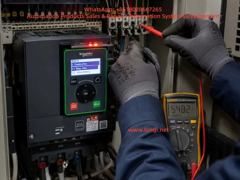
Step 2: Disconnect input power and wait for DC bus discharge
A VFD contains high-voltage DC bus capacitors.
Even after incoming AC power is switched off, dangerous DC voltage may remain inside the drive for several minutes.
The safe procedure is:
- Disconnect the upstream power supply.
- Wait until the keypad and display are fully off.
- Follow the discharge waiting time specified on the drive label or manual.
- Measure DC bus voltage and confirm it has fallen to a safe level.
- Only then remove wiring or perform measurements.
Never touch braking terminals, DC bus terminals, or internal power boards before confirming that the DC bus voltage has discharged.
Step 3: Inspect the braking resistor visually
Inspect the braking resistor for:
- Burn marks
- Discoloration
- Cracked housing
- Melted insulation
- Loose terminals
- Burned cable lugs
- Strong burnt smell
- Broken leads
- Overheating marks on nearby wiring
- Contact with the cabinet or grounded metal parts
- Poor ventilation
- Dust accumulation
- Oil contamination
- Moisture or condensation
If the braking resistor shows clear signs of overheating or physical damage, do not continue running the equipment before verifying resistor selection and braking circuit condition.
Step 4: Isolate the external braking resistor circuit
This is one of the most important diagnostic steps.
After disconnecting power and confirming the DC bus has discharged, remove the two braking resistor wires from the drive braking terminals. Label both wires clearly to prevent incorrect reconnection.
Then power the drive again and observe whether the bUF / BUF fault remains.
Result A: Fault disappears after braking resistor is disconnected
This strongly suggests that the fault is in the external braking circuit.
Possible causes include:
- Braking resistor short circuit
- Braking resistor resistance too low
- Braking cable short circuit
- Cable insulation damage
- Wrong wiring
- Ground fault
- External braking unit failure
- Moisture or conductive dust around braking terminals
Result B: Fault remains after braking resistor is disconnected
If the drive still displays bUF / BUF immediately after power-on with the braking resistor completely disconnected, the fault is more likely inside the drive.
The most likely internal causes are:
- Braking IGBT short circuit
- Braking transistor damage
- Braking IGBT driver circuit failure
- Braking power board failure
- DC bus detection circuit failure
- Control board fault
- Internal contamination or damaged PCB traces
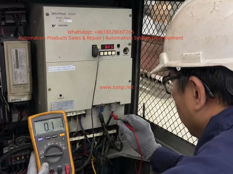
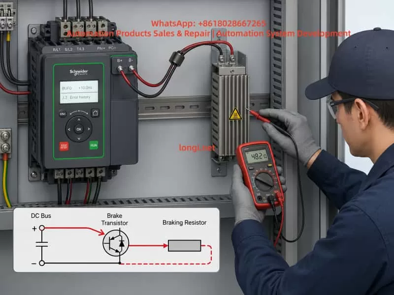
Step 5: Measure the braking resistor resistance
The braking resistor should be measured with at least one side disconnected from the drive.
Important measurement rules:
- Do not measure the resistor while it is still fully connected to the drive.
- Compare the measured value with the resistor nameplate value.
- A resistance close to zero ohms is abnormal.
- A resistance far below the specified value is dangerous.
- Infinite resistance may indicate an open resistor.
- Measure insulation resistance between the resistor terminals and ground.
- Inspect for unstable readings caused by poor internal connections.
For example, if a braking resistor is rated at 50 ohms but measures only a few ohms or nearly zero ohms, it must not be connected to the VFD. Such a low resistance may cause excessive braking current and can damage the internal braking IGBT.
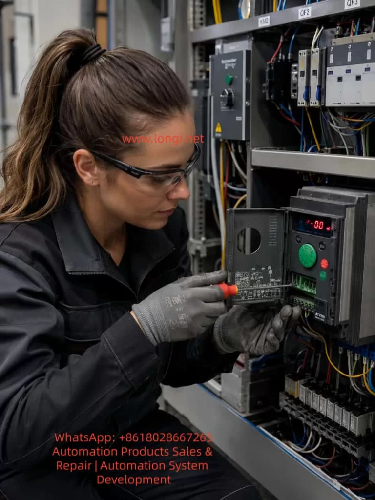
Step 6: Inspect braking cables and terminals
Braking cable problems are frequently overlooked.
Check for:
- Crushed cable sections
- Cable trapped by cabinet doors
- Cable installed too close to hot components
- Heat damage caused by braking resistor radiation
- Hardened or cracked insulation
- Cable touching cabinet metal
- Loose crimped terminals
- Oxidized terminal lugs
- Loose screws
- Conductive dust around terminals
- Incorrect grounding of cable shields
- Braking cable mixed with motor output cables
- Wrong connection between braking terminals and DC bus terminals
For vibrating equipment such as hoists, presses, centrifuges, winding machines, conveyors, and woodworking equipment, terminal looseness and cable fatigue are especially common.
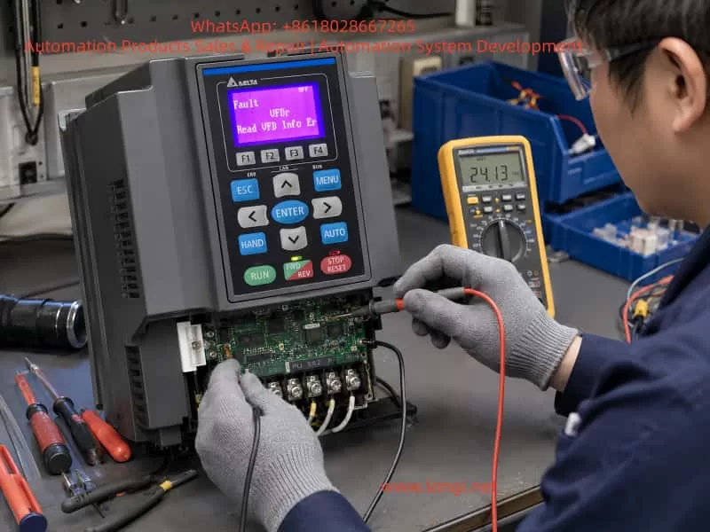
Step 7: Check the internal braking IGBT and driver circuit
If the external braking resistor and wiring are confirmed normal, but the bUF / BUF fault remains, the internal braking circuit must be inspected.
Common repair checks include:
- Measuring the braking transistor using diode-test mode
- Comparing readings with a known-good drive of the same model
- Checking for near-zero resistance between braking terminals and DC bus terminals
- Inspecting the braking IGBT for short circuit conditions
- Inspecting the power board for burn marks
- Checking gate resistors
- Checking optocouplers
- Checking driver ICs
- Checking snubber capacitors and suppression components
- Checking for damaged PCB tracks
- Checking whether the braking IGBT gate is permanently driven ON
The internal topology differs between drive models. Therefore, measurements must be interpreted according to the specific Schneider Altivar model and power structure.
High-power drives, integrated IGBT modules, coated power boards, and high-voltage systems should be tested by qualified VFD repair personnel.
6. Problems Caused by Incorrect Braking Resistor Selection
Incorrect braking resistor selection is one of the main reasons braking faults repeat after repair.
6.1 Resistance value too low
When braking resistor resistance is too low, braking current becomes excessive whenever the braking IGBT turns on.
This may cause:
- Excessive braking IGBT current
- bUF / BUF braking circuit fault
- Braking transistor overheating
- Damage to the braking module
- Excessive resistor heating
- DC bus instability
- Blown semiconductor devices
- Damage to the power board
It is incorrect to assume that “lower resistance always means stronger braking.” The braking resistor value must never be lower than the minimum resistance specified for the VFD model.
6.2 Resistance value too high
If braking resistance is too high, insufficient current flows through the braking resistor.
This may result in:
- DC bus overvoltage during deceleration
- Overvoltage trips
- Long stopping time
- Failure to meet process stop requirements
- Poor speed control during high-inertia deceleration
- Safety risk in lifting or winding applications
6.3 Resistor power rating too low
Correct resistance value alone is not enough. The resistor power rating must also match the regenerative energy and braking duty cycle.
An undersized resistor may cause:
- Excessive surface temperature
- Thermal protection trip
- Internal resistor wire oxidation
- Cracking or deformation
- Resistance drift
- Insulation breakdown
- Cable damage
- Cabinet overheating
- Secondary short circuit conditions
The resistor must be selected based on peak braking power, average braking power, deceleration frequency, machine inertia, and expected duty cycle.
7. Relationship Between Deceleration Time and Braking Faults
When a drive trips while stopping, many users immediately increase the deceleration time. This can help in some cases, but it is not a universal solution.
If the drive is tripping on DC bus overvoltage, increasing deceleration time can reduce regenerative power and lower the stress on the braking circuit.
However, if the drive has a bUF / BUF short-circuit-related fault, increasing deceleration time may not solve the root cause.
This is because the actual issue may be:
- Shorted braking IGBT
- Shorted braking resistor
- Shorted braking cable
- Incorrect braking terminal wiring
- Failed external braking unit
- Faulty braking driver circuit
A practical distinction is:
- DC bus overvoltage during deceleration: Review deceleration time, braking resistor size, and regenerative energy.
- Braking resistor overload: Review resistor power rating, braking duty cycle, and thermal parameters.
- bUF / BUF type fault: Prioritize braking circuit hardware, wiring, and braking transistor diagnostics.
Different fault codes require different troubleshooting logic.
8. Common Causes of Internal Braking IGBT Failure
When the internal braking transistor or braking module fails, there is usually an underlying cause.
8.1 Braking resistor value too low
This is one of the most common causes. An excessively low resistance value creates excessive braking current and overloads the braking IGBT.
8.2 Short circuit in braking wiring
Cable damage, water ingress, wiring error, crushed insulation, and loose terminals can create near-short-circuit conditions in the braking branch.
8.3 Insufficient braking resistor capacity
An undersized braking resistor may overheat repeatedly. Over time, it can develop insulation failure, internal damage, or unstable resistance, eventually affecting the braking circuit.
8.4 Frequent rapid stopping
High-inertia equipment that repeatedly decelerates in a short time places heavy stress on the braking IGBT.
Typical examples include:
- Hoists
- Centrifuges
- Large fans
- Winding machines
- Presses
- Conveyors
- Mixers
- High-speed spindles
8.5 Poor cooling
Blocked airflow, damaged fans, high cabinet temperature, clogged heatsinks, or poor ventilation can significantly reduce braking IGBT lifetime.
8.6 High input voltage
When the input voltage is high, the normal DC bus voltage is already elevated. During deceleration, the bus voltage rises faster and the braking system must absorb more energy.
8.7 Surge voltage and electrical disturbances
Lightning, switching surges, welding machines, unstable generators, poor grounding, and high-power load switching can damage the braking driver circuit or power module.
9. Verification Procedure After Repair
After replacing a braking resistor, repairing a braking unit, or repairing the VFD power board, the drive should not be returned directly to full production.
A staged verification process is recommended.
9.1 Power-on test without load
Power on the drive with the braking circuit correctly connected and confirm that no bUF / BUF fault appears.
9.2 Low-frequency motor test
Run the motor at a low frequency and observe:
- Output current
- Motor sound
- Motor vibration
- DC bus behavior
- Drive temperature
- Fault history
- Braking circuit response
9.3 Normal-frequency operation
Increase to normal operating frequency and verify that current, speed, and output stability are normal.
9.4 Light-load deceleration test
Use a relatively long deceleration time first. Confirm that the system stops smoothly and that no braking fault occurs.
9.5 Normal process deceleration test
Gradually restore normal deceleration settings. Monitor braking resistor temperature, DC bus behavior, fault history, and stopping performance.
9.6 Repeated braking test
For applications such as lifting systems, centrifuges, winding machines, presses, and high-inertia machinery, perform repeated brake cycles to confirm stable operation under thermal conditions.
A braking circuit that operates correctly when cold may still fail after repeated braking cycles if the resistor, wiring, or IGBT is thermally unstable.
10. Engineering Measures to Prevent bUF / BUF Braking Faults
Reliable braking system performance requires attention to system design, installation, parameter configuration, maintenance, and operating practice.
10.1 Design stage
- Select braking resistor resistance according to the drive manufacturer’s minimum allowable value.
- Select resistor power and thermal capacity according to load inertia and braking duty cycle.
- Use an external braking unit or regenerative unit for frequent or high-energy braking applications.
- Provide thermal protection for braking resistors.
- Ensure sufficient ventilation space around the braking resistor.
- Consider regenerative energy calculations for high-inertia systems.
10.2 Installation stage
- Install braking resistors away from combustible materials.
- Use high-temperature-rated cables.
- Keep braking wiring separate from motor output cables where practical.
- Tighten all braking terminals to the specified torque.
- Keep wiring away from sharp edges and moving mechanical parts.
- Prevent conductive dust accumulation.
- Maintain cabinet sealing, ventilation, and moisture protection.
10.3 Parameter stage
- Set deceleration time according to actual load inertia.
- Configure braking-related parameters correctly.
- Use suitable thermal protection settings.
- Avoid unnecessary fast-stop commands.
- Do not copy braking parameters blindly from another machine.
- Review braking duty requirements after process changes.
10.4 Maintenance stage
- Periodically inspect braking resistor temperature and appearance.
- Measure braking resistor resistance during scheduled maintenance.
- Tighten terminals regularly.
- Inspect cable insulation.
- Clean dust from the electrical cabinet.
- Check cooling fans and heatsinks.
- Review braking-related fault history.
- Inspect for abnormal odor, discoloration, or heat damage.
10.5 Operating stage
- Avoid repeated emergency stops under heavy load.
- Avoid frequent rapid acceleration and deceleration unless the braking system is designed for it.
- Do not install a lower-resistance braking resistor without confirming the drive’s limits.
- Do not continue production after repeated braking faults.
- Investigate intermittent faults before they become catastrophic power failures.
11. Conclusion
A Schneider VFD bUF / BUF type fault generally indicates an abnormal condition in the braking circuit. The most important suspected causes are braking resistor short circuit, braking resistor value too low, incorrect wiring, braking cable failure, damaged internal braking IGBT, braking driver circuit malfunction, or external braking unit failure.
The correct troubleshooting process is not simply resetting the drive or extending the deceleration time. A reliable diagnosis should follow this sequence:
- Determine whether the fault occurs during power-on, start-up, deceleration, or repeated operation.
- Disconnect power and confirm DC bus discharge.
- Inspect the braking resistor and braking wiring.
- Disconnect the external braking resistor to isolate the circuit.
- Measure resistor resistance and insulation condition.
- Inspect braking terminals and cables.
- If the fault remains with the external circuit disconnected, inspect the internal braking IGBT, driver circuit, and power board.
- After repair, verify the drive through staged no-load, light-load, full-load, and repeated braking tests.
Only by treating the braking resistor, braking transistor, DC bus, wiring, parameters, and machine inertia as one complete system can bUF / BUF braking faults be accurately diagnosed and permanently eliminated.