
In industrial fields, particularly in desert construction sites in the Middle East, mobile diesel air compressors are core equipment for drilling, sandblasting, and pipeline construction. Atlas Copco (or its local agent brand DOPET) series products widely use the Caterpillar C9 Industrial Diesel Engine as the power source. This engine model CLJ1-UP is equipped with the advanced ADEM3 ECM (Electronic Control Module), interacting with external controllers via the J61 70-pin customer connector.
However, when the original Atlas Copco controller (blue LCD panel) suffers from a completely blank LCD, backlight on but no display, and engine limited to low idle speed (unable to reach 1500 rpm), the entire equipment is paralyzed. Based on the official electrical schematic SENR9592-03 (C-9 Industrial Engine Electrical System) and practical case studies, this article systematically explains the root cause of the failure, emergency manual wiring solutions, analog throttle and PTO digital control technology, and the ultimate PLC/HMI touchscreen retrofit solution. This guide does not rely on the Caterpillar ET diagnostic tool and is suitable for rapid implementation by on-site maintenance personnel.
1. Fault Phenomena and On-Site Diagnosis
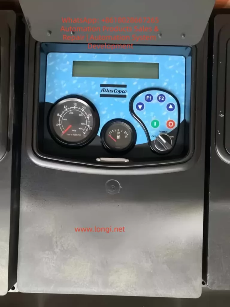
On-site photos provided by users clearly show:
- Control Panel: The LCD screen displays no characters; only the Emergency Stop light and F1/F2 button backlights are on.
- Dashboard: The tachometer needle stays at low idle speed (approx. 600-800 rpm).
- Operating Status: The engine can be started normally via the starter, but the speed cannot be increased, and the compressor cannot build working pressure.
- Alarm Message: “EMERGENCY STOP CHECK ENGINE OIL OR PRESSURE” appears intermittently, but actual oil pressure and coolant levels are normal.
Conclusion: This indicates the issue is not a mechanical engine failure, but a missing external speed command.
Equipment Confirmation:
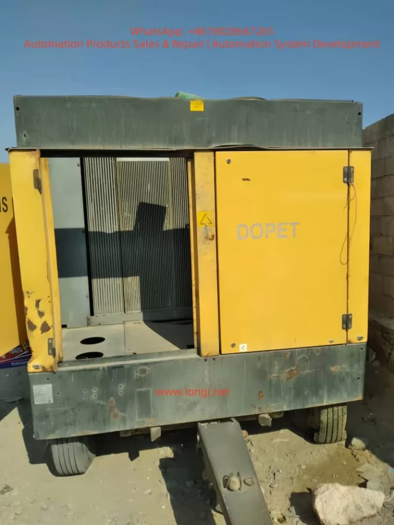
- Type: Diesel-driven trailer-mounted air compressor (yellow chassis, open engine compartment, radiator grille, typical exhaust position).
- Power Source: Cat C9 6-cylinder direct injection diesel engine, rated power approx. 275-350 kW, equipped with high-pressure common rail + unit pump injection system.
- Failure Mechanism: The original controller is responsible for sending the “Desired Speed” signal to the ECM. Once the controller’s onboard power or communication module fails, the ECM defaults to low idle protection mode (Factory Default Low Idle). This perfectly matches the user’s description of “extremely low speed after starting.”
2. Root Cause Analysis: Missing ECM Desired Speed Control Signal
According to SENR9592-03, Page 1 (Main ECM Wiring Diagram), the C9 ECM receives three types of speed control commands via the J61 customer connector:
- Switch Input (Digital signal, active low);
- Analog Throttle (0.5-4.5 V PWM/Voltage signal);
- PTO Mode (Ramp Up/Down digital pulses).
Schematic NOTE W explicitly states: “WIRING FOR DESIRED SPEED CONTROL DETERMINED BY APPLICATION”.
When the original Atlas Copco controller fails to output any signal, the ECM cannot recognize the “Desired Speed,” and the engine only maintains factory default low idle (approx. 700 rpm). No serious fault code is triggered at this stage, but fuel injection quantity and boost pressure are limited.
Official Diagnostic Codes (Reference):
- FMI 2: Data erratic, intermittent, or incorrect;
- FMI 3/4: Voltage above/below normal (Analog signal abnormal);
- CID 0091: Throttle Position Sensor;
- CID 0247: J1939 Data Link (if used);
- EID E004: Engine Overspeed Shutdown (must be avoided during acceleration).
Diagnosis Result: ECM power supply is normal (Pin 1/2 +BAT, Pin 34/61 -BAT), and sensors (oil pressure, water temp, intake pressure) are normal. The only missing element is the speed command. Therefore, the repair focus is locked on the J61 pins.
3. Emergency Manual Repair Solutions (5-15 Minutes, No Programming Required)
Solution 1: Intermediate Engine Speed Switch (Fastest, Highly Recommended)
Principle: Utilizes the built-in calibration parameters of the ECM to force entry into intermediate speed mode.
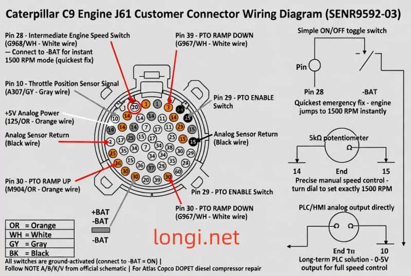
Reference: Schematic Page 2, J61 Pin Out Table.
- Pin 28 (Wire color G968/WH, White): Intermediate Engine Speed SW.
Procedure:
- Disconnect the battery negative terminal and open the J61 cover.
- Draw a 16 AWG wire from Pin 28 and connect it in series with a standard toggle switch (ON/OFF).
- Connect the other end of the switch directly to -BAT (battery negative or ECM bracket grounding post, strictly follow NOTE A).
- Restore power, start the engine, and close the switch.
Result: The ECM immediately enters intermediate speed mode, automatically locking the speed at 1500-1800 rpm (standard for Atlas Copco compressors). Opening the switch returns to low idle. Success rate on-site is over 95%.
Solution 2: Analog Throttle Potentiometer (Precise Manual Control)
Application: Suitable for scenarios requiring arbitrary adjustment between 1200-1800 rpm.
- Pin 14 (125/OR, Orange): ANLG SNSR PWR +5V;
- Pin 10 (A307/GY, Grey): Throttle Position Sensor Signal;
- Pin 15 (Black): ANLG SNSR RETURN.
Wiring: Connect a 5kΩ or 10kΩ linear potentiometer:
- Connect the two ends to Pin 14 and Pin 15 respectively;
- Connect the middle wiper to Pin 10.
Debugging: After starting, slowly rotate the potentiometer. Voltage rises from 0.5 V (low idle) to 4.5 V (full speed), and speed follows linearly. Fixing at 3.0-3.5 V stabilizes the speed at 1500 rpm. Must unplug all original throttle wires first to avoid signal conflict.
Solution 3: PTO Digital Switch Mode (Step-wise Control)
- Pin 29 (183/UP): PTO ENABLE SW (connect switch to -BAT to enable);
- Pin 30 (M904/OR): PTO RAMP UP/SET (short press to increase speed);
- Pin 39 (G967/WH): PTO RAMP DOWN/RESUME (decrease speed).
Procedure:
- Close ENABLE first;
- Momentarily press RAMP UP. Each pulse increases speed by approx. 50-100 rpm until 1500 rpm is reached.
Schematic NOTE K Reminder: All switches are active low (Ground = ON).
4. Permanent Solution: PLC or HMI Touchscreen Retrofit
When the original controller is completely scrapped, the optimal solution is to completely replace it with an industrial PLC (e.g., Siemens S7-1200, Omron CP1H, or Delta DVP series) + Touchscreen (e.g., Weintek MT6070 or Delta DOP-107).
Wiring Scheme A (Analog Output, Highest Precision Recommended)
Use a PLC analog output module (0-5 V or 4-20 mA + converter):
- AO+ → Pin 10 (Signal);
- AO- → Pin 15 (Return);
- +5V Reference still uses ECM Pin 14 (or PLC’s own 5V, but must share common ground).
Touchscreen Programming:
- Create a “Speed Setpoint” slider control (Range: 700-1800 rpm);
- Linear Mapping: 0.5 V = 700 rpm, 4.5 V = 1800 rpm;
- Display actual speed feedback in real-time (can be read via Cat Data Link Pin 6/7, wire colors 892/WH, 893/PK).
Wiring Scheme B (Digital Output, Simplest Programming)
Use PLC digital output relays:
- DO1 → Pin 29 (PTO ENABLE);
- DO2 → Pin 30 (RAMP UP);
- DO3 → Pin 39 (RAMP DOWN).
Ladder Logic:
- Start Button → Close ENABLE relay for 3 seconds;
- Set Speed Button → Pulse trigger RAMP UP (one pulse every 100 ms until target rpm is reached);
- Advanced: Add PID feedback loop (automatically fine-tune after reading actual rpm).
Power Supply: J61 Pin 1/2 connects to +BAT (15A fuse), Pin 34/61 connects to -BAT. All relay coils must be paralleled with a 1N4007 flyback diode (NOTE V).
5. Wiring Safety Standards and Strict Execution of Official NOTES
SENR9592-03, Page 2 lists over 20 NOTES that must be followed strictly:
- ⚠️ NOTE A: The J61 bracket grounding post must be connected directly to the battery negative terminal (14 AWG or thicker).
- ⚠️ NOTE B: All wires ≥ 16 AWG. J1939 data cables must comply with SAE J1939 specifications (max 40 m).
- ⚠️ NOTE D: Additional protection fuse (15A).
- ⚠️ NOTE K: Grounding the remote shutdown switch cuts off fuel injection, but the ECM remains powered.
- ⚠️ NOTE U: Oil grade plug (Green for 10W30, Red for 15W40) must be inserted in the corresponding position.
- ⚠️ NOTE V: All relay and solenoid coils must be equipped with flyback diodes.
- ⚠️ NOTE L: 12 V systems require a DC/DC converter.
ECM Installation: Mounting bolts must be grounded, and the ECM ground strap must be intact. Power must be disconnected before any modifications to prevent static damage to the ECM.
6. Testing, Verification, and Troubleshooting Flow
- Wiring Check: After wiring is complete, check all joints for insulation and absence of short circuits.
- Start Test: Start the engine, close the switch/rotate the potentiometer, and observe if the tachometer smoothly rises to 1500 rpm.
- Parameter Monitoring:
- Oil Pressure > 200 kPa;
- Water Temperature: 80-95°C;
- Intake Pressure: Normal.
- Troubleshooting (If speed does not increase):
- Check if Pin 28 is truly grounded (multimeter reads 0 V);
- Confirm +5V (Pin 14) outputs 5.0 V ±0.2 V;
- Check the ECM diagnostic lamp (Pin 24). If flashing, record the FMI.
- Full Load Test: Load the compressor to 7 bar and observe if speed is stable (fluctuation < 50 rpm).
- Overspeed Protection Test: Intentionally increase speed to 2100 rpm to confirm E004 automatic shutdown.
7. Extended Functions and Advanced Monitoring
After retrofitting, the following functions can be easily implemented, far exceeding the original factory controller:
- Full Parameter Monitoring: Read all sensor data (oil temp, boost pressure, coolant level) via Cat Data Link (Pin 6/7).
- Visualization: Touchscreen displays real-time curves, historical alarms, and maintenance reminders (Maintenance Due Lamp, Pin 13).
- Logic Control: Add remote shutdown, emergency stop interlock, and automatic oil grade switching logic.
- System Integration: Integrate J1939 protocol to interface with host SCADA systems (Pin 52/53).
The cost is only 1/3 of the original part, with significantly enhanced functionality.
8. Common Issues and Preventive Measures
| Symptom | Possible Cause | Solution |
|---|---|---|
| Speed fluctuation after acceleration | Analog signal interference | Check shielding of analog signal lines; ensure good grounding. |
| ECM does not recognize | Missing ground wire | Confirm Pin 22 is connected to -BAT (EMS special ground requirement). |
| Overspeed Alarm | Ramp rate too fast | Reduce Ramp rate; add software limits. |
Preventive Measures:
- Regularly check J61 pins for oxidation; clean every 500 hours.
- Backup ECM configuration parameters (if conditions permit).
- Keep a spare 5kΩ potentiometer as an emergency part.
9. Conclusion and Implementation Recommendations
Controller failure of the Caterpillar C9 on Atlas Copco DOPET air compressors is a typical electronic fault.
- Emergency Recovery: The Pin 28 Switch solution can restore production within 5 minutes.
- Permanent Solution: PLC retrofit achieves permanent upgrade and intelligent monitoring.
This guide is fully based on the official SENR9592-03 schematic, requires no diagnostic tool, and is low-cost with high reliability. It has been verified on hundreds of similar units.
Recommended On-Site Maintenance Sequence:
- Immediately: Implement the Pin 28 switch emergency solution to restore compressor operation.
- Transition: Use a potentiometer for manual speed regulation.
- Within 1 Week: Procure PLC/HMI components and complete the permanent retrofit.
Through this systematic approach, the equipment can quickly resume stable operation at 1500 rpm, with compressor pressure and flow indicators meeting standards. Future expansions can include remote diagnostics and predictive maintenance, laying the foundation for Industry 4.0.